
Datasheet

29
SURFACE MOUNT ALUMINUM ELECTROLYTIC CAPACITORS
CHIP TYPES
·Chip type higher capacitance in larger case size
·Designed for surface mounting on high density PC board
·Applicable to automatic insertion machine using carrier tape
·Complied to the RoHS directive
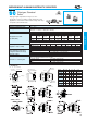
Chip type, Standard
Series
SSCC
Unit : mm
C±0.2
E±0.2
W±0.2
0.5~0.8
ØD±0.5
0.3 max.
0.4 max.
5.3±0.2
Lot No.
※Voltage
Capacitance
(Ø4, Ø5, Ø6.3×5.3mmL)
(Ø12.5×13.5mmL)
+
-
Negative
+
-
27
6V
Positive
Plastic plateform
B±0.2
※Voltage mark for
6.3V is `6a
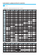
Solvent Proof
WV
100V
Item Characteristics
Operating temperature range
Leakage current max.
Capacitance tolerance
Dissipation factor max.
(at 120Hz, 20
°°
C)
Low temperature characteristics
(Impedance ratio at 120Hz)
Load life
(after application of the rated
voltage for 2000 hours at 85
°°
C)
Shelf life(at 85
°°
C)
Resistance to soldering heat
-40 ~ +85°C
WV100 I = 0.01CV or 3μA whichever is greater (after 2 minutes)
WV160 I = 0.04CV + 100μA(after 1 minutes)
±20% at 120Hz, 20°C
Figures in( ) are for small size, over the 6.3×5.8(
Ø
D×L)
After 1000 hours no load test, leakage current, capacitance and tanδare same as load life value.
Leakage current
Capacitance change
tanδ
Less than specified value
Within ±20% of initial value (Small size : ±25%)
Less than 200% of specified value
WV
tanδ
4
0.35
(0.40)
6.3
0.28
(0.35)
10
0.20
(0.24)
16
0.16
(0.20)
25
0.13
(0.16)
35
0.12
(0.15)
50
0.09
(0.12)
WV
tanδ
63
0.12
100
0.12
160
0.20
200
0.20
250
0.20
400
0.25
450
0.25
WV
Z-25°C/Z+20°C
Z-40°C/Z+20°C
4
6
12
6.3
5
10
10
4
8
16
3
6
25
2
4
35 ~ 100
2
3
160 ~ 250
3
6
400 ~ 450
6
10
Series Code
● DRAWING
ØD×L
4
×
5.3
5
×
5.3
6.3
×
5.3
6.3
×
5.8
6.3
×
7.7
8
×
6.2
8
×
10
10
×
10
12.5
×
13.5
W
4.8
6.0
7.1
A
2.4
2.4
3.3
2.9
3.2
4.6
B
4.3
5.3
6.6
6.6
6.6
8.3
8.3
10.3
12.8
C
4.3
5.3
6.6
6.6
6.6
8.3
8.3
10.3
12.8
E
1.0
1.4
2.2
2.2
2.2
2.3
3.1
4.5
4.5
R
0.5~0.8
0.5~0.8
0.5~0.8
0.5~0.8
0.5~0.8
0.5~0.8
0.8~1.1
0.8~1.1
1.1~1.4
UPGRADE
The following specifications shall be satisfied when the capacitors are restored to 20°C
after exposing them at 250°C for 30 seconds.
Leakage current
Capacitance change
tanδ
Less than specified value
Within ±10% of initial value
Less than specified value