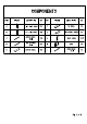
COMPONENTS PART FIGURE DESCRIPTION | QTY | PART FIGURE DESCRIPTION | QTY A | RIGHT SIDE PANEL| TPC | F TOP PANEL | 1PC B LEFT SIDE PANEL| 1Pc | @ C&P Stable SHELF| Pe ¢ rd UPPER FRONT BACK RENAL | PCS D yd BOTTOM FRONT | 1p ’ DOOR 1PC E & BOTTOM PANEL | 1PC | J UPPER SACK | tee
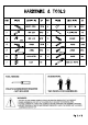
HARDWARE & TOOLS PART FIGURE DESCRIPTION | QTY | PART FIGURE DESCRIPTION | QTY 1 Wy WOODEN DOWEL | PCS | 8 4 SHELF PIN | PCS 8430 2 a CAM BOLT | PCS | 9 SN PLASTIC BAR | 1PG 3 CAM LOCK | PCS | 10 ANCHOR PCS 8 #1540 Tu, 4 “nny SCREW PCs | 11 SCREW PCS $3%12 SCREW PCS | 13 a? SCREW PCs $3%12 D=6| © $312 D=5 6 LOCK CATCH | 1PC 14 SCREW 1PC LOCK 1PC TEMPLATE PAPER TOOL NEEDED: SUGGESTION: PHILIPS SCREWDRIVER REQUIRED 4 « HOT INCLUDED TWO PEOPLE FOR ASSEMBLING WARNINGS! 1.
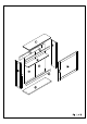
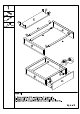
STEP 1: Attach rails panels A & B with dowels (1). . Attach panel E to panels A & B and secure with cam locks (3). .
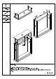
cure with cam locks (3) & screw and rail J. rail J and s tops of panels A&B 3. Attach panel F to panels Screw cam bolts (2) into panel F. 2. Insert dowels to the 4).
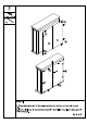
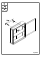
STEP 3: 1. Attach back panels H to the cabinet and secure the four corners with screws 2. Insert plastic bar (9) between back panels H and finish securing the back panels with screws (4).
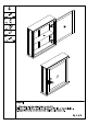
4 oe 6 1PC STEP 4: 1. Attach door | to the cabinet with screws (13). 2. Insert shelf pins 8) to panels A & B and rest shelf G on the shelf pins. 3. Attach latch the door and cabinet with screws (5).