
User Manual

Secure Digital (SD) Bus Protocol Description
TriFlash with SD Interface Product Manual (Preliminary), Rev. 1.2 © 2002/2003 SANDISK CORPORATION
4-3
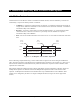
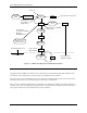
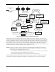
Start bit
always '0'
0 0 Content 1
Response content: mirrored command and status
information (R1 response), OCR register (R3 response)
or RCA (R6) protected by 7 bit CRC checksum
Transmitter bit:
'0'=card response
Total length = 48 bits
End bt:
always '1'
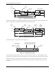
0 0 Content = CID or CSD CRC 1
Total length = 136 bits
End bt:
always '1'
R1, R3, R6
R2
Figure 4-5. Response Token Format
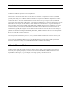
In the CMD line, the MSB bit is transmitted first, whereas the LSB bit is transmitted last.
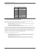
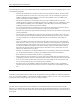
When the wide bus option is used, the data is transferred 4 bits at a time (refer to Figure 4-6). Start and end bits, as
well as the CRC bits, are transmitted for every one of the DAT lines. CRC bits are calculated and checked for every
DAT line individually. The CRC status response and Busy indication will be sent by the device to the host on DAT0
only (DAT1-DAT3 during that period are “do not care”).
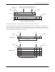
Start bit
always '0'
Block length
End bt:
always '1'
Standard busy
(only DAT0 used):
MSB (4095)
0 CRC 1
LSB (0)
Start bit
always '0'
Block length /4
End bt:
always '1'
MSN
LSN
DAT3
0 4095 3 CRC 1
DAT2
0 4094 2 CRC 1
DAT1
0 4093 1 CRC 1
DAT0
0 4092 0 CRC 1
Wide bus (all four
data lines used):
Figure 4-6. Data Packet Format