
User Manual


SPI Protocol Definition
5-4 TriFlash with SD Interface Product Manual (Preliminary), Rev. 1.2 © 2002/2003 SANDISK CORPORATION
Once the programming operation is completed, the host must check the results of the programming using the
SEND_STATUS command (CMD13). Some errors (e.g., address out of range, write protect violation) are detected
during programming only. The only validation check performed on the data block and communicated to the host via
the data-response token is CRC and general Write Error indication.
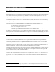
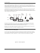
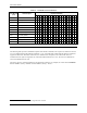
In Multiple Block write operation the stop transmission will be done by sending ’Stop Tran’ token instead of ’Start
Block’ token at the beginning of the next block. In case of Write Error indication (on the data response) the host
shall use SEND_NUM_WR_BLOCKS (ACMD22) in order to get the number of well written write blocks. The data
token’s description is given in Section 5.2.4.
From
Host to
Card
From
Card to
Host
Host to Car
Stop
Tran
Token
DataIn
DataOut
Command
Busy
Data From
d
Data_
Response
Busy
Data
Response
and Busy
From Card
Response
Data
Block
Start
Block
Token
From
Host to
Card
Command
Figure 5-5. Multiple Block Write Operation
Resetting the CS signal while the device is busy, will not terminate the programming process. The device will
release the dataOut line (tristate) and continue to program. If the device is reselected before the programming is
done, the dataOut line will be forced back to low and all commands will be rejected.
Resetting a device (using CMD0) will terminate any pending or active programming operation. This may destroy
the data formats on the device. It is the host’s responsibility to prevent it.
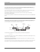
5.1.5. Erase and Write Protect Management
The erase and write protect management procedures in the SPI mode are identical to the SD Bus mode. While the
device is erasing or changing the write protection bits of the predefined sector list it will be in a busy state and will
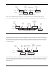
hold the dataOut line low. Figure 5-6 illustrates a “no data” bus transaction with and without busy signaling.
Figure 5-6. “No Data” Operations