
User Manual


SPI Protocol Definition
5-8 TriFlash with SD Interface Product Manual (Preliminary), Rev. 1.2 © 2002/2003 SANDISK CORPORATION
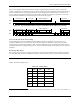
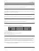
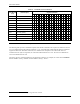
Table 5-1. Command Classes in SPI Mode
Supported Commands Card CMD Class
(CCC)
Class Description
0 1 9 10 12 13 16 17 18 24 25 27 28 29 30 32 33 38 42 55 56 58 59
class 0 Basic + + + + + + + +
class 1 Not supported in SPI
class 2 Block read + + +
class 3 Not supported in SPI
class 4 Block write + + +
class 5 Erase + + +
class 6 Write-protection (Optional) + + +
class 7 Lock Card (Optional)
2
+
class 8 Application specific + +
class 9 Not supported in SPI
class 10-11 Reserved
5.2.2.1. Detailed Command Description
The following table provides a detailed description of the SPI bus commands. The responses are defined in Section
5.2.3. The table below lists all TriFlash commands. A “yes” in the SPI mode column indicates that the command is
supported in SPI mode. With these restrictions, the command class description in the CSD is still valid. If a
command does not require an argument, the value of this field should be set to zero. The reserved commands are
reserved in SD Bus mode as well.
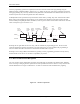
The binary code of a command is defined by the mnemonic symbol. As an example, the content of the Command
field for CMD0 is (binary) ‘000000’ and for CMD39 is (binary) ‘100111.’
2
The Lock Card command is currently not supported in the TriFlash.