APS-3 User Manual Revision 2.
APS-3 User Manual © 2011 ALTUS Positioning Systems Inc. All rights reserved. ALTUS, the ALTUS logo, and APS-3 are trademarks of ALTUS Positioning Systems Inc. registered in the U.S. and other countries. No part of this document may be copied, used or reproduced without the prior written permission of ALTUS Positioning Systems.
Table of Contents 1. Introduction ..................................................................................................... 5 1.1. User Notice ....................................................................................................................... 5 1.1.1. FCC ....................................................................................................................5 1.1.2. CE Mark ...........................................................................................
3.4.2. Slant Height Dimensions .................................................................................. 20 4. Factory AsteRx2/AsteRx2e receiver Settings.............................................. 21 4.1. Uploading a script/text file using RxControl ............................................................... 21 4.2. Line-by-line entry .......................................................................................................... 23 5. Frequently Asked Questions.................
1. Introduction 1.1. User Notice This section provides information regarding FCC, CE, Warranty and Customer Service with Support. All specifications are typical and subject to change without prior notice. ALTUS Positioning Systems reserves the right for improvements and changes to this document, products and services without notice or obligation. 1.1.1. FCC The APS-3 has been tested and found to comply with Part 15 of the FCC rules.
1.1.4. Customer Service and Support Contact your ALTUS dealer for first-line support. Further problems or questions, please contact ALTUS Positioning Systems support. support@altus-ps.com http://www.altus-ps.com/support or write to ALTUS Positioning Systems 20725 Western Avenue, Suite 100 Torrance, CA 90501 (310) 541-8139 office (310) 541-8257 fax 1.2. Foreword Congratulations on purchasing the APS-3.
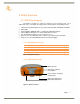
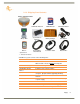
2. APS-3 Overview 2.1. APS-3 Key Features The APS-3 is an all-in-one, cable free solution for your Surveying needs. It’s a simple and easy to use GNSS surveying product, which provides the following features: 136 Channel AsteRx2e GNSS receiver, with L1/L2/L2C GPS, GLONASS and SBAS.
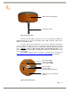
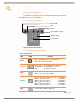
SIM & SD Card Compartment UHF Radio Antenna Figure 2: APS-3, Rear View The rear view of the APS-3 shows the door to access the SD card and SIM card. GNSS raw data can be saved to the SD Card, and the SIM card allows cellular service with the internal GSM modem. The ports and the product label can be seen on the underside of the APS-3. There are 3 ports: two serial ports and one external power input port.
2.1.3.
2.1.4. Using the APS-3 For problem free operation, the user should read this APS-3 User Manual thoroughly before first use of the APS-3. 2.1.5. APS-3 Front Panel Bluetooth® RTK Power Internal Data Logging GNSS Satellite Power Button Figure 4: APS-3 Front Panel Label 2.1.6.
2.1.7. Power Button The power button is located on the front panel, and has the primary function for turning the APS-3 ON or OFF. Secondary functions are for data logging On/Off, soft and hard receiver reboot/reset. In a soft reboot the receiver resets the firmware, while retaining the current configurations. In a hard reboot the APS-3 will recall the receiver’s boot configuration file (default reboot).
2.1.9. Power Input The external power input is via the 4-pin LEMO connector. The specifications are: Power Consumption: 3.6W Typical External Power: +9VDC to +15VDC Current: 300mA @ 12V DC Nominal Table 6: Power Cable Description Wire Color Function RED Power (+) BLACK Ground (-) GREEN Not Used WHITE Not Used 2.1.10. SIM Card Figure 6: SIM Card & SD Card Compartment SIM Card Holder Eject button 2.1.10.1.
2.1.10.2. Installing SIM Card Turn Off APS-3 to install or remove SIM card. Damage to SIM card may occur if installed or ejected with power ON. To Install/Remove SIM Card: Unlock SIM & SD Card compartment by turning lock groove horizontal Open SIM & SD Card compartment Push the yellow SIM Card holder eject button to release SIM Holder Pull out SIM Holder Place SIM Card in SIM Card Holder Hold the SIM Card in holder upside down Using the guide, slide SIM Card Holder in the slot.
2.1.11.3.
2.1.11.4. Known Compatible SD Cards Not all removable SD cards are guaranteed to be compatible with the APS-3. The following SD cards have been successfully tested for APS-3 compatibility.
3. APS-3 Device & Specifications 3.1. Internal UHF Radio Specification Operating Frequency: 406 MHz to 470 MHz Occupied Bandwidth: 6.25kHz, 12.5kHz or 25kHz Gain: 145-146dBm What you need to know How do I configure my UHF Radio? My rover is not receiving RTK corrections. 3.2.
3.3. Battery & Charger The APS-3 comes with two lithium-ion rechargeable batteries with a typical operating time between 8 to 10 hours. Specifications Battery Type: Lithium ION Voltage: +6.2VDC to 8.4VDC Capacity: 2500mAH 3.3.1. Battery Charger AC Adapter Input: 100-240VAC ~50/60Hz 1.7A Output: 19.0VDC @ 3.16A 3.3.2.
A fully discharged battery will take approximately 2 hours to fully charge and may not light the LED status indicator when first mounted. 3.3.3. APS-3 Battery Installation and Replacement Removing the battery in use will cause the APS-3 to restart or turn OFF. Use the battery status indicator in data collection software to confirm which battery is “in use” before hot-swapping batteries.
3.4. GNSS Antenna Offsets 3.4.1. NGS Calibration Figure 8: Phase Center Location Phase Center Location NGS Vertical Offsets Absolute Relative L1 Offset (mm) 94.7 113.5 L2 Offset (mm) 86.2 94.1 Absolute - http://www.ngs.noaa.gov/ANTCAL/images/ant_info.abs APS_APS-3 NONE ALTUS GNSS RCVR/ANT, P/N:10015, PNL TO N NGS ( 3) 1.3 1.1 -0.5 -1.0 0.0 -1.0 -1.4 -1.9 0.0 -0.3 -0.6 1.8 2.0 -0.5 -0.5 3.2 -1.4 -1.3 -2.5 -2.9 94.7 1.9 -0.3 86.2 -1.0 -3.1 1.5 -0.1 1.1 0.4 0.5 0.0 0.1 0.0 -0.2 -0.6 -3.
3.4.2.
4. Factory AsteRx2/AsteRx2e receiver Settings The instructions below should be used to reconfigure an APS-3 back to ALTUS Default. This is the #1 method for resolving problems with the APS-3’s operation, and should always be executed before contacting ALTUS support. Reconfiguring the APS-3 back to ALTUS Default sets the unit as a Rover, Message Type: RTCM v3.1, Logged Data Type: SBF.
4.1.2. Select the prepared text file from the PC and click Open. Figure 11: Script File 4.1.3.The APS-3 has been successfully reconfigured to the ALTUS Default when the commands appear in the bottom left corner of the main RxControl window. The commands and return messages will populate the expert console.
Figure 13: Script Commands and Responses 4.2. Line-by-line entry 4.2.1.Connect the APS-3 to the PC via the serial cable and start RxControl.
4.2.2.In the Tools tab select the Expert Console Menu and the Expert Console window will open. . Figure 15: Expert Console 4.2.3.Select the SSRC1 tab and type the first command into the text box. sgpf, GP1, Output,none, LevelLow, then hit the Enter Key. Figure 16: Expert Console SSRC1 Display 4.2.4.The command will populate the screen (< “input”) followed by a return message (> “output”) indicating whether the command was accepted/valid ($R) or an invalid command ($R?).
For more information concerning RxControl, Expert Console, and command messages refer to the Septentrio RxControl Manual on the ALTUS CD 4.2.5. Continue entering the commands into the text box, when completed the APS-3that is connected has been reconfigured to the ALTUS Default.
Commands for Manual entry: sgpf, GP1, Output,none, LevelLow sgpf, GP2, Output,none, LevelLow sgpf, GP3, Output,none, LevelHigh setDataInOut, COM3, CMD,SBF+NMEA setDataInOut, COM2, RTCMv3,SBF+NMEA setDataInOut, COM1, CMD ,SBF setDataInOut, DSK1, CMD,SBF+NMEA setCOMSettings, COM1, baud2400,BITS8,NO,BIT1,NONE setCOMSettings, COM2,baud115200,BITS8,NO,BIT1, none (or RTS|CTS for V2)* setCOMSettings, COM3, baud115200 ,BITS8 ,NO ,BIT1 , RTS|CTS sdcu,lowlatency,20,auto,0 sem,PVT,10 sst,all snt,all spm,rover,all,geod
5. Frequently Asked Questions 5.1. Question: Where is the Antenna Reference Point (ARP) located on the APS3? Answer: The NGS ARP is the bottom of the bolt on the underside of the APS-3. The NGS calibration value for the APS-3 L1 vertical offset is 113.5 mm. For more information see section 2.4 GNSS Antenna Offsets: http://www.ngs.noaa.gov/cgi-bin/query_cal_antennas.prl?Model=APS Figure 18: NGS ARP Diagram 5.2.
Factory AsteRx2/AsteRx2e receiver Settings in section 3 of this manual to upload that file into the APS-3. 5.6. Question: What are the correct specifications for a GSM SIM card in order for it to operate with the APS-3? Answer: There are three key items that must be specified to get the correct GSM SIM card and service from your cellular service provider; GSM SIM card (not UMTS) Data service only No IMEI number (i.e.
5.12. Question: How do I change my settings in SurvCE to use metric, International Feet, or US Survey Feet for the distance? Answer: These settings must be set when starting a new job. In the File tab select Job Settings, then select the System tab and choose the Distance Units from the drop down menu. 5.13. Question: How do I stop the APS-3 from logging automatically on startup? (SurvCE users only) Answer: The APS-3 remembers the settings set during the last configuration and uses these upon restart.
be verified in the “Help” tab of RxControl in the “Receiver Identification” menu. It can also be checked using SurvCE and FIELDGenius. 5.18. Question: My receiver will not respond to commands, why not? Answer: A setting in the APS-3 may have been incorrectly set causing a disruption in communication. Power the unit off, remove all power sources, turn the unit back on. After the unit boots, perform a hard reset and upload the default script.
6.
7. Table of Figures Figure 1: APS-3, Front View ............................................................................................... 7 Figure 2: APS-3, Rear View .................................................................................................. 8 Figure 3: APS-3, Bottom View ............................................................................................. 8 Figure 4: APS-3 Front Panel Label ...............................................................................