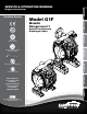
" 150# A W Certified Quality 4.18 106.29 8.37 212.71 12.03 305.56 3.54 89.81 4X 1.22 30.96 4.19 106.43 SUCTION PORT Environmental Management System 1" NPT ISO 14001 Certified 6.73 171.07 Metallic Design Level 1 7.44 AIR INLET 188.98 1/2 NPT Natural Gas-Operated Diaphragm Pumps .38 MOUNTING HOLES 9.53 Quality System ISO 9001 Certified .41 10.32 Model G1F 3.93 99.89 6.39 162.31 5.31 135 2: INSTAL & OP 2.00 50.80 3.22 81.76 DISCHARGE PORT 1" NPT 1.63 41.28 4: Gas END Original 2.
Safety Information IMPORTANT WARNING When used for toxic or aggressive fluids, the pump should always be flushed clean prior to disassembly. Read the safety warnings and instructions in this manual before pump installation and start-up. Failure to comply with the recommendations stated in this manual could damage the pump and void factory warranty. Before maintenance or repair, shut off the compressed gas line, bleed the pressure, and disconnect the gas line from the pump.
SECTION 4: GAS END......................................11 • Aluminum Gas Valve Assembly • Stainless Steel Gas Valve Assembly • Pilot Valve Assembly • Intermediate Assembly SECTION 5: WET END......................................14 • Diaphragm Drawings • Diaphragm Servicing • Pumping Hazardous Liquids 2: INSTAL & OP 3: EXP VIEW 7: WARRANTY SECTION 7: WARRANTY & CERTIFICATES.....
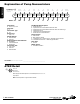
1: PUMP SPECS Explanation of Pump Nomenclature Your Model G #: __ ____ __ __ __ __ __ __ __ __ __ ____ (fill in from pump nameplate) Pump Brand Model #: Pump Size Check Valve Wetted Diaphragm/ Check Valve Non-Wetted Porting Material Check Valve Seat Material Options Pump Style Muffler Options Pump Brand Pump Size 1F 1" Check Valve Type B Ball Design Level Design Level Wetted Material S Stainless Steel A Aluminum Diaphragm/Check Valve Materials B Nitrile/Nitrile T
Performance G1F Metallic MODEL G1F Metallic Performance Curve HEADS UP TO • 100 psi or 231 ft. of water (7 bar or 70 meters) 3 25(42.5) 80 80 P SI (5 60 MAXIMUM OPERATING PRESSURE • 100 psi (7 bar) DISPLACEMENT/STROKE • .11 Gallon / .42 liter 60 PS ar) SHIPPING WEIGHT • Aluminum 28 lbs. (13kg) • Stainless Steel 43 lbs. (20kg) These pump models are designed to pump the following fluids: Crude Oil, Salt Water, Drilling Mud, Condensate, Lubrication Oils, Glycol, Caustic Liquids, and Acids.
1: PUMP SPECS Dimensional Drawings G1F Metallic - NPT Dimensions in inches (mm dimensions in brackets). Dimensional Tolerance:±1/8" (± 3mm) The dimensions on this drawing are for reference only. A certified drawing can be requested if physical dimensions are needed. 10.25 260.35 10.25 260.35 9.09 230.80 9.09 230.80 5.13 130.18 5.13 130.18 12.88 327.09 12.88 327.09 AIR INLET 1/2 NPT AIR INLET 1/2 NPT 12.03 305.56 12.03 305.56 6.40 162.43 6.40 162.43 .41 10.32 .41 10.
Dimensional Drawings G1F Metallic - ANSI Flange 1: PUMP SPECS Dimensions in inches (mm dimensions in brackets). Dimensional Tolerance:±1/8" (± 3mm) The dimensions on this drawing are for reference only. A certified drawing can be requested if physical dimensions are needed. 9.10 231.14 10.25 260.35 10.25 260.35 5.13 130.18 3.87 98.17 5.13 10.25 130.18 260.35 9.10 231.14 4.64 DISCHARGE PORT DISCHARGE PORT 117.73 4.64 3.87 117.73 98.17 1" 150# ANSI RF1"FLANGE 150# ANSI RF FLA 3.87 98.17 5.13 130.
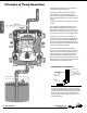
Principle of Pump Operation 2: INSTAL & OP Gas-Operated Double Diaphragm pumps are powered by compressed gas, nitrogen or natural gas. The main directional (gas) control valve ① distributes compressed gas to an gas chamber, exerting uniform pressure over the inner surface of the diaphragm ②. At the same time, the exhausting gas ③ from behind the opposite diaphragm is directed through the gas valve assembly(s) to an exhaust port ④.
Recommended Installation Guide 1 020.063.000 Filter VENTING WARNING: This filter is equipped with a stainless steel manual drain. The port is 1/8" NPT. When draining moisture from the filter, first shut off the natural gas supply. 2 020.058.000 REGULATOR WITH GAGE PRESSURE WARNING: This regulator is to be installed at point of use with the pump. The maximum gas supply is 400psi. Full line pressure needs to be regulated below 400psi prior to the regulator installation position.
Troubleshooting Guide Symptom: Pump Cycles Once 2: INSTAL & OP Pump Will Not Operate / Cycle Pump Cycles and Will Not Prime or No Flow Pump Cycles Running Sluggish / Stalling, Flow Unsatisfactory Product Leaking Through Exhaust Premature Diaphragm Failure Unbalanced Cycling Potential Cause(s): Deadhead (system pressure meets or exceeds gas supply pressure). Gas valve or intermediate gaskets installed incorrectly. Bent or missing actuator plunger. Pump is over lubricated.
Composite Repair Parts Drawing Torque: 90 in/lbs 8 18 11 4 32 17 ATTACH EYELET TO ONE OF THE FOUR CAPSCREWS ITEM # 11 31 Torque: 90 in/lbs 25 7 21 12 20 9 26 30 28 16 1 5 3: EXP VIEW 2 3 29 27 13 6 10 23 14 14 15 24 Torque: 350 in/lbs 2 23 29 Torque: 450 in/lbs 22 OPTIONAL OVERLAY Service & Repair Kits 476.228.000 Gas End Kit Seals, O-Rings, Gaskets, Retaining Rings, Valve Assembly and Pilot Valve Assembly 476.228.
3: EXP VIEW Composite Repair Parts List Item Part Number Description 1 031-179-000 Stainless Steel Gas Valve Assembly (use with Option B) Stainless Steel Gas Valve Assembly 031-179-363 Qty 1 Item Part Number Description Qty 21 560-001-363 O-Ring 2 560-001-360 O-Ring 2 22 560-091-360 O-Ring (metallic seats only) 8 with FKM O-rings (used with Option D) 1 560-091-611 O-Ring (metallic seats only) 8 031-183-000 Gas Valve Assembly 1
000 ����Assembly, sub-assembly; and some purchased items 010 ����Cast Iron 015 ����Ductile Iron 020 ����Ferritic Malleable Iron 080 ����Carbon Steel, AISI B-1112 110 �����Alloy Type 316 Stainless Steel 111 �����Alloy Type 316 Stainless Steel (Electro Polished) 112 �����Alloy C 113 �����Alloy Type 316 Stainless Steel (Hand Polished) 114 �����303 Stainless Steel 115 �����302/304 Stainless Steel 117 �����440-C Stainless Steel (Martensitic) 120 ����416 Stainless Steel (Wrought Martensitic) 148 ����Hardcoat Anod
Gas Distribution Valve Assembly 1-F 1-E Valve Assembly for Aluminum Mid Sections Natural Gas Assembly Parts List 1-D 1-D Item Part Number Description Qty 1 031-183-000 Gas Valve Assembly 1 1-A 095-109-157 Valve Body 1 1-B 031-139-000 Sleeve and Spool Set 1 1-C 132-029-357 Bumper 2 1-D 560-020-360 O-Ring 10 1-E 165-127-157 Cap, End 2 1-F 170-032-330 Capscrew 8 1-C 1-B 1-B 1-E Item Part Number Description Qty 1 031-183-363 Gas Valve Assembly (FKM) 1
Pilot Valve Servicing With Pilot Valve removed from pump. Step 1: Remove snap ring (4-F). Step 2: Remove sleeve (4-B), inspect O-Rings (4-C), replace if required. Step 3: Remove spool (4-D) from sleeve (4-B), inspect O-Rings (4-E), replace if required. Step 4: Lightly lubricate O-Rings (4-C) and (4-E). Reassemble in reverse order.
Intermediate Assembly 4: AIR END 28 Intermediate Assembly Drawing Step 1: Remove plunger, actuator (25) from center of intermediate pilot valve cavity. Step 2: Remove Ring, Retaining (26), discard. Step 3: Remove bushing, plunger (7), inspect for wear and replace if necessary with genuine parts. Step 4: Remove O-Ring (21), inspect for wear and replace if necessary with genuine parts.
Diaphragm Service Drawing, with Overlay Torque: 450 in/lbs Torque: 350 in/lbs sandpiperpump .
Diaphragm Servicing Step 1: With manifolds and outer chambers removed, remove diaphragm assemblies from diaphragm rod. DO NOT use a pipe wrench or similar tool to remove assembly from rod. Flaws in the rod surface may damage bearings and seal. Soft jaws in a vise are recommended to prevent diaphragm rod damage. Step 1.A: NOTE: Not all inner diaphragm plates are threaded. Some models utilize a through hole in the inner diaphragm plate.
PUMPING HAZARDOUS LIQUIDS When a diaphragm fails, the pumped liquid or fumes enter the natural gas end of the pump. Fumes are exhausted into the surrounding environment. When pumping hazardous or toxic materials, the exhaust gas must be piped to an appropriate area for safe disposal. See illustration #1 at right. This pump can be submerged if the pump materials of construction are compatible with the liquid being pumped. The natural gas exhaust must be piped above the liquid level.
Written Warranty 5 - YEAR Limited Product Warranty Quality System ISO 9001 Certified • Environmental Management Systems ISO 14001 Certified Warren Rupp, Inc. (“Warren Rupp”) warrants to the original end-use purchaser that no product sold by Warren Rupp that bears a Warren Rupp brand shall fail under normal use and service due to a defect in material or workmanship within five years from the date of shipment from Warren Rupp’s factory.
EC Declaration of Conformity In accordance with ATEX Directive 94/9/EC, Equipment intended for use in potentially explosive environments. Manufacturer: Warren Rupp, Inc.®, A Unit of IDEX Corportion 800 North Main Street, P.O. Box 1568, Mansfield, OH 44902 USA EN 60079-25: 2004 For pumps equipped with Pulse Output ATEX Option KEMA Quality B.V.