
User guide

hdf3mdl2sm-rev1110 Model HDF3-M & HDF4-M Page 8
REASSEMBLY
All procedures for reassembling the pump are the reverse of the previous
instructions with further instructions as shown:
1. The diaphragm assemblies are to be installed with the natural bulge outward
or toward the head of the center screw. Make sure both plates are installed with
outer radii against the diaphragm. After all components are in position in a vise and
hand tight, set a torque wrench for 480 inch pounds (40 ft. pounds) (54.23 Newton
meters) or, 600 inch pounds (50 ft. pounds) (67.79 Newton meters) for Santoprene,
using a (3/8") allen head socket. After each diaphragm sub assembly has been
completed, thread one assembly into the shaft (held near the middle in a vise having
soft jaws to protect the nish) making sure the stainless steel washer is in place on
the capscrew.
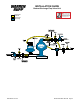
Make sure 1/4"-20 mounting screw has been removed and that the bumper (Item
#19 on drawing) is in place in the shaft.
Install this sub assembly into the pump and secure by placing the outer chamber
housing and capscrews on the end with the diaphragm. This will hold the assembly
in place while the opposite side is installed. Make sure the last diaphragm assembly
is torqued to 30 ft. lbs. (40.67 Newton meters) before placing the outer diaphragm
over the capscrews. If the holes in the diaphragm ange do not line up with the holes
in the chamber ange, turn the diaphragm assembly in the direction of tightening
to align the holes so that the capscrews can be inserted. This nal torquing of the
last diaphragm assembly will lock the two diaphragm assemblies together. Place
remaining outer chamber on the open end and tighten down the securing nuts
gradually and evenly on both sides.
Caution should be used while reassembling Flap valves. The valves are designed
for some preload over the retainer hinge pad. This is done to insure proper face contact
with the seat. After all parts are in place, tighten the lock nuts down on the assembly
to the point where visual inspection shows that seat and valve face mate without gap.
This is important for dry prime. However, after priming action has started, valves will
function due to differential pressure without concern or trouble.
PILOT VALVE
The pilot valve assembly is accessed by removing the main air distribution valve
body from the pump and lifting the pilot valve body out of the intermediate housing.
Most problems with the pilot valve can be corrected by replacing the o-rings.
Always grease the spool prior to inserting it into the sleeve. If the sleeve is removed
from the body, reinsertion must be at the chamfered side. Grease the o-rings to slide
the sleeve into the valve body. Securely insert the retaining ring around the sleeve.
When reinserting the pilot valve, push both plungers (located inside the intermediate
bracket) out of the path of the pilot valve spool ends to avoid damage.
PILOT VALVE ACTUATOR
Bushings for the pilot valve actuators are threaded into the intermediate bracket
from the outside. The plunger may be removed for inspection or replacement. First
remove the air distribution valve body and the pilot valve body from the pump. The
plungers can be located by looking into the intermediate. It may be necessary to
use a ne piece of wire to pull them out. The bushing can be turned out through the
inner chamber by removing the outer chamber assembly. Replace the bushings if pins
have bent.