
User guide


hdf3mdl2sm-rev1110 Model HDF3-M & HDF4-M Page 4
PRINCIPLE OF PUMP OPERATION
This ap swing valve pump is powered by compressed air and is a 1:1
pressure ratio design. It alternately pressurizes the inner side of one diaphragm
chamber, while simultaneously exhausting the other inner chamber. This causes the
diaphragms, which are connected by a common rod, to move endwise. Air pressure
is applied over the entire surface of the diaphragm, while liquid is discharged from
the opposite side. The diaphragm operates under a balanced condition during the
discharge stroke, which allows the unit to be operated at discharge heads over 200
feet (61 meters) of water head.
Since the diaphragms are connected by a common rod, secured by plates to the
center of the diaphragms, one diaphragm performs the discharge stroke, while the
other is pulled to perform the suction stroke in the opposite chamber.
For maximum diaphragm life, keep the pump as close to the liquid being pumped
as possible. Positive suction head in excess of 10 feet of liquid (3.048 meters) may
require a back pressure regulating device. This will maximize diaphragm life.
Alternate pressuring and exhausting of the diaphragm chamber is performed by
means of an externally mounted, pilot operated, four-way spool type air distribution
valve. When the spool shifts to one end of the valve body, inlet air pressure is applied
to one diaphragm chamber and the other diaphragm chamber exhausts. When the
spool shifts to the opposite end of the valve body, the porting of chambers is reversed.
The air distribution valve spool is moved by an internal pilot valve which alternately
pressurizes one side of the air distribution valve spool, while exhausting the other
side. The pilot valve is shifted at each end of the diaphragm stroke by the diaphragm
plate coming in contact with the end of the pilot spool. This pushes it into position for
shifting of the air distribution valve.
The chambers are manifolded together with a suction and discharge ap-type
valve for each chamber, maintaining ow in one direction through the pump
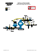
INSTALLATION & START-UP
Locate the pump as close to the product being pumped as possible, keeping suc-
tion line length and number of ttings to a minimum. Do not reduce line size.
For installations of rigid piping, short exible sections of hose should be installed
between pump and piping. This reduces vibration and strain to the piping system. A
surge suppressor is recommended to further reduce pulsation in ow.
This pump was tested at the factory prior to shipment and is ready for operation.
It is completely self-priming from a dry start for suction lifts of 20 feet (6.096 meters)
or less. For suction lifts exceeding 20 feet of liquid, ll the chambers with liquid prior
to priming.
AIR SUPPLY
Air supply pressures cannot exceed 125 psi (8.61 bar). Connect the pump air inlet
to an air supply of sufcient capacity and pressure required for desired performance.
When the air line is solid piping, use a short length of exible hose [not less than
3/4" (19mm) in diameter] between pump and piping to eliminate strain to pipes.
AIR INLET & PRIMING
For start-up, open an air valve approximately 1/2" to 3/4" turn. After the unit primes,
an air valve can be opened to increase ow as desired. If opening the valve increases
cycling rate, but does not increase ow rate, cavitation has occurred, and the valve
should be closed slightly.
For the most efcient use of compressed air and the longest diaphragm life, throttle
the air inlet to the lowest cycling rate that does not reduce ow.
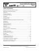
SERVICE AND OPERATING MANUAL
Model HDF3-M & HD4F-M
Type 2
Heavy Duty Flap Valve
II 2GD T5