
User guide


hdf3mdl2sm-rev1110 Model HDF3-M & HDF4-M Page 6
A NOTE ABOUT AIR VALVE LUBRICATION
The SANDPIPER pump’s pilot valve and main air valve assemblies are designed
to operate WITHOUT lubrication. This is the preferred mode of operation. There
may be instances of personal preference, or poor quality air supplies when lubrica-
tion of the compressed air supply is required. The pump air system will operate with
properly lubricated compressed air supplies. Proper lubrication of the compressed air
supply would entail the use of an air line lubricator (available from Warren Rupp) set
to deliver one drop of 10 wt., non-detergent oil for every 20 SCFM of air the pump
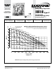
consumed at its point of operation. Consult the pump’s published Performance Curve to
determine this.
It is important to remember to inspect the sleeve and spool set routinely. It should
move back and forth freely. This is most important when the air supply is lubricated.
If a lubricator is used, oil accumulation will, over time, collect any debris from the
compressed air. This can prevent the pump from operating properly.
Water in the compressed air supply can create problems such as icing or
freezing of the exhaust air causing the pump to cycle erratically, or stop operating. This
can be addressed by using a point of use air dryer to supplement a plant’s air drying
equipment. This device will remove excess water from the compressed air supply and
alleviate the icing or freezing problem.
ESADS+PLUS:
EXTERNALLY SERVICEABLE AIR DISTRIBUTION SYSTEM
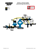
Please refer to the exploded view drawing and parts list in the Service Manual sup-
plied with your pump. If you need replacement or additional copies, contact your local
Warren Rupp Distributor, or the Warren Rupp factory Literature Department at the
number shown below. To receive the correct manual, you must specify the MODEL
and TYPE information found on the name plate of the pump.
MODELS WITH 1" SUCTION/DISCHARGE OR LARGER,
AND METAL CENTER SECTIONS:
The main air valve sleeve and spool set is located in the valve body mounted on
the pump with four hex head capscrews. The valve body assembly is removed from
the pump by removing these four hex head capscrews.
With the valve body assembly off the pump, access to the sleeve and spool set
is made by removing four hex head capscrews (each end) on the end caps of the
valve body assembly. With the end caps removed, slide the spool back and forth in
the sleeve. The spool is closely sized to the sleeve and must move freely to allow for
proper pump operation. An accumulation of oil, dirt or other contaminants from the
pump’s air supply, or from a failed diaphragm, may prevent the spool from moving
freely. This can cause the spool to stick in a position that prevents the pump from
operating. If this is the case, the sleeve and spool set should be removed from the
valve body for cleaning and further inspection.
Remove the spool from the sleeve. Using an arbor press or bench vise (with an
improvised mandrel), press the sleeve from the valve body. Take care not to damage
the sleeve. At this point, inspect the o-rings on the sleeve for nicks, tears or abrasions.
Damage of this sort could happen during assembly or servicing. A sheared or cut
o-ring can allow the pump’s compressed air supply to leak or bypass within the air
valve assembly, causing the pump to leak compressed air from the pump air exhaust
or not cycle properly. This is most noticeable at pump dead head or high discharge
pressure conditions. Replace any of these o-rings as required or set up a routine,
preventive maintenance schedule to do so on a regular basis. This practice should
include cleaning the spool and sleeve components with a safety solvent or equivalent,
inspecting for signs of wear or damage, and replacing worn components.
To re-install the sleeve and spool set, lightly lubricate the o-rings on the sleeve
with an o-ring assembly lubricant or lightweight oil (such as 10 wt. air line lubricant).
Re-install one end cap, gasket and bumper on the valve body. Using the arbor press
or bench vise that was used in disassembly, carefully press the sleeve back into the
valve body, without shearing the o-rings. You may have to clean the surfaces of the
valve body where the end caps mount. Material may remain from the old gasket. Old
material not cleaned from this area may cause air leakage after reassembly. Take care