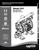
Original Instructions Certified Quality Model S05 3: EXP VIEW 2: INSTAL & OP Non-Metallic Design Level 2 1: PUMP SPECS SERVICE & OPERATING MANUAL TROP EGR T 4: AIR END Quality System ISO 9001 Certified TELNI TPNF 5: WET END Environmental Management System ISO 14001 Certified 6: OPTIONAL 831 Warren Rupp, Inc. 7: WARRANTY A Unit of IDEX Corporation 800 N. Main St., Mansfield, Ohio 44902 USA Telephone 419.524.8388 Fax 419.522.7867 SANDPIPERPUMP.COM © Copyright 2016 Warren Rupp, Inc.
Safety Information IMPORTANT WARNING When used for toxic or aggressive fluids, the pump should always be flushed clean prior to disassembly. Read the safety warnings and instructions in this manual before pump installation and start-up. Failure to comply with the recommendations stated in this manual could damage the pump and void factory warranty. Before maintenance or repair, shut off the compressed air line, bleed the pressure, and disconnect the air line from the pump.
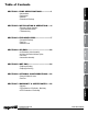
SECTION 5: WET END......................................14 • Diaphragm Drawing • Diaphragm Servicing SECTION 6: OPTIONAL CONFIGURATIONS.....16 • Solenoid Shifted Air Valve • Dual Port SECTION 7: WARRANTY & CERTIFICATES.....18 • Warranty • CE Declaration of Conformity - Machinery • ATEX Declaration of Conformity sandpiperpump . com s05nmdl2sm-rev0716 2: INSTAL & OP 3: EXP VIEW 4: AIR END SECTION 4: AIR END........................................
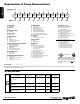
1: PUMP SPECS Explanation of Pump Nomenclature Your Model #: (fill in from pump nameplate) S __ ____ __ __ Pump Brand Pump Size Check Valve Design Level S XX X X Model #: Pump Brand S Check Valve Type Soilid Ball Design Level Design Level B U Z 0 6 C X X __ __ ____ Porting Options Pump Style Pump Options Kit Options X X X XX Kit Options (cont.
Performance S05 NON-METALLIC HEADS UP TO • 100 psi or 231 ft. of water (7 bar or 70 meters) DISPLACEMENT/STROKE • .026 Gallon / .098 liter 0P 4 80 70 60 SI 2 12 (20) Bar ) 14 (24) 2 Bar 20 PS ) I (1.3 0 16 (27) ar) I (2.7 10 0 8 (13.5) .08 B 40 PS 30 0 .44 SI (4 20 1 ar) I (5 60 P 40 6 (10) 8B 10 (17) PS 50 3 4 (7) (6. 1 6 Bar) Air Inlet 3 2 Pressure 4 10 0 SHIPPING WEIGHT • Polypropylene 16 lbs. (8kg) • PVDF 18 lbs.
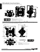
7 4 5 DISCHARGE PORT 1/2" FNPT (INTERNAL) 1" MNPT (EXTERNAL) 10.11 257 2 3 1 A 1.48 3.07 78 1.75 44 MANIFOLD CAN ROTATE 90 FROM VERTICAL CENTERLINE AIR INLET 1/4 FNPT S05 Non-Metallic Center Ported Options D 11.54 293 MANIFOLD CAN ROTATE 90 FROM VERTICAL CENTERLINE 1: PUMP SPECS Dimensions in inches (metric dimensions in brackets). Dimensional Tolerance .125" (3mm). 1.48 9.79 249 DISCHARGE PORT 1/2" FNPT (INTERNAL) 1" MNPT (EXTERNAL) AIR INLET 10.11 257 1/4 FNPT A 3.07 78 5.
Principle of Pump Operation Air-Operated Double Diaphragm (AODD) pumps are powered by compressed air or nitrogen. As inner chamber pressure (P1) exceeds liquid chamber pressure (P2), the rod ⑤ connected diaphragms shift together creating discharge on one side and suction on the opposite side. The discharged and primed liquid’s directions are controlled by the check valves (ball or flap)⑥ orientation.
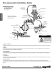
Recommended Installation Guide Available Accessories: 1. Surge Suppressor 2. Filter/Regulator 3. Air Dryer 1 Unregulated Air Supply to Surge Suppressor Surge Suppressor 2: INSTAL & OP Pressure Gauge Shut-Off Valve Note: Surge Suppressor and Piping must be supported after the flexible connection.
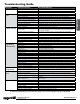
Troubleshooting Guide Pump Cycles Once Pump Will Not Operate / Cycle Pump Cycles and Will Not Prime or No Flow Potential Cause(s): Deadhead (system pressure meets or exceeds air supply pressure). Air valve or intermediate gaskets installed incorrectly. Bent or missing actuator plunger. Pump is over lubricated. Lack of air (line size, PSI, CFM). Check air distribution system. Discharge line is blocked or clogged manifolds. Deadhead (system pressure meets or exceeds air supply pressure).
Composite Repair Parts Drawing ILLUSTRATION SHOWS DIRECTION OF DIAPHRAGMS 36 Torque: 70 in/lbs DIAPHRAGM CONFIGURATION DETAIL NOTE TO ASSEMBLY THE DIAPHRAGMS FOR BOTH CONFIGURATIONS SHOWN ABOVE ARE TO BE INSTALLED WITH CONVOLUTIONS FACING TOWARDS CENTER OF PUMP INLINE DISCHARGE MANIFOLD OPTION 3: EXP VIEW Torque: 50 in/lbs Torque: 70 in/lbs Torque: 120 in/lbs Torque: 70 in/lbs Torque: 50 in/lbs MUFFLER OPTION OVERLAY OPTION INLINE DISCHARGE MANIFOLD OPTION 35 Service & Repair Kits 476.202.
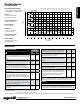
Item Part Number 1 031.166.000 031.166.002 031.166.003 031.167.000 031.167.002 031.168.000 031.168.002 031.169.000 031.194.000 031.194.002 031.195.000 031.195.003 2 050.027.354 050.027.357 050.027.360 050.022.600 3 095.091.000 095.091.001 4 114.023.551 114.023.559 5 115.140.115 115.140.308 6 132.034.360 7 135.036.506 8 165.110.551 165.110.559 9 171.062.115 171.062.308 10 171.063.115 171.063.308 11 171.064.115 171.064.308 12 171.066.115 171.066.308 13 171.075.115 171.075.308 14 196.178.520 196.178.
MATERIAL CODES 000 010 015 020 080 110 111 112 113 3: EXP VIEW 114 115 117 120 148 150 152 155 156 157 158 162 165 166 170 180 305 306 307 308 309 313 330 332 333 335 337 351 353 354 356 357 358 359 360 363 Assembly, sub-assembly; and some purchased items Cast Iron Ductile Iron Ferritic Malleable Iron Carbon Steel, AISI B-1112 Alloy Type 316 Stainless Steel Alloy Type 316 Stainless Steel (Electro Polished) Alloy C Alloy Type 316 Stainless Steel (Hand Polished) 303 Stainless Steel 302/304 Stainless Steel
MAIN AIR VALVE ASSEMBLY PARTS LIST Item 1 1-A 1-B 1-C 1-E 1-F 1-G 1-H 1-I 1-J Air Distribution Valve Servicing See repair parts drawing, remove screws. Step 1: Remove end cap retainer (1-G). Step 2: Remove end cap (1-E). Step 3: Remove spool part of (1-B) (caution: do not scratch). Step 4: Press sleeve (1-B) from body (1-A). Step 5: Inspect O-Rings (1-C) and replace if necessary. Step 6: Lightly lubricate O-Rings (1-C) on sleeve (1-B). Step 7: Press sleeve (1-B) into body (1-A).
Air Valve with Stroke Indicator Assembly Drawing, Parts List 1-K 1-H 1-J 1-B 1-F 1-E 1-B 1-D 1-C 1-I 1-D 1-C 4: AIR END 1-F 1-A 1-E 1-G Air Distribution Valve Servicing See repair parts drawing, remove screws. Step 1: Remove end cap retainer (1-G). Step 2: Remove end cap (1-E), bumper (1-D). Step 3: Remove spool part of (1-B) (caution, do not scratch). Step 4: Press sleeve (1-B) from body (1-A). Step 5: Inspect O-Rings (1-C) and replace if necessary.
Pilot Valve Servicing With Pilot Valve removed from pump. Step 1: Remove snap ring (3-F). Step 2: Remove sleeve (3-B), inspect O-Rings (3-C), replace if required. Step 3: Remove spool (3-D) from sleeve (3-B), inspect O-Rings (3E), replace if required. Step 4: Lightly lubricate O-Rings (3-C) and (3-E). Reassemble in reverse order. PILOT VALVE ASSEMBLY PARTS LIST Item 3 3-A 3-B 3-C 3-D 3-E 3-F Part Number 095.091.000 095.087.551 755.051.000 560.033.360 775.055.000 560.023.360 675.037.
Intermediate Assembly Drawing 4 32 26 7 30 4: AIR END 29 Intermediate Assembly Drawing Step 1: Remove plunger, actuator (29) from center of intermediate pilot valve cavity. Step 2: Remove Ring, Retaining (30), discard. Step 3: Remove bushing, plunger (7), inspect for wear and replace if necessary with genuine parts. Step 4: Remove O-Ring (26), inspect for wear and replace if necessary with genuine parts. Step 5: Lightly lubricate O-Ring (26) and insert into intermediate.
Diaphragm Service Drawing 19 13 15 27 31 6 11 28 14 19 Use With TPE Diaphragms Only 25 27 15 13 Diaphragm Orientation 14 Torque: 120 in/lbs Install diaphragm and spacer as shown above. 11 Diaphragm Service Drawing - with Overlay 13 16 15 27 31 6 14 11 15 16 25 27 Torque: 120 in/lbs 13 Diaphragm Orientation 14 Install diaphragm and spacer as shown above. 11 5: WET END 28 Diaphragm Service Drawing - with One-Piece Bonded 13 15 11 31 6 14 28 25 15 13 14 11 sandpiperpump .
DIAPHRAGM SERVICING Step 1: With manifolds and outer chambers removed, remove diaphragm assemblies from diaphragm rod. DO NOT use a pipe wrench or similar tool to remove assembly from rod. Flaws in the rod surface may damage bearings and seal. Soft jaws in a vise are recommended to prevent diaphragm rod damage. Step 1.A: NOTE: Not all inner diaphragm plates are threaded. Some models utilize a though hole in the inner diaphragm plate.
Solenoid Shifted Air Valve Drawing 41 8 20 Wiring Diagram 40 3rd Terminal for ground. #2 Terminal Neutral (Negative) 30 39 42 26 #1 Terminal Power (Positive) 26 42 30 12 4 22 38 SOLENOID SHIFTED AIR VALVE PARTS LIST (Includes all items used on Composite Repair Parts List except as shown) Item 4 38 39 SOLENOID SHIFTED OPERATION BEFORE INSTALLATION BEFORE WIRING THE SOLENOID, make certain it is compatible with your system voltage. 40 41 42 sandpiperpump .
Dual Port Option Drawing 1" NPT or 1" BSP Tapered External ½" NPT or ½" BSP Tapered Internal Connection ½" NPT or ½" BSP Tapered Connection 37 38 ½" NPT or ½" BSP Tapered Connection Illustration for Dual Port Suction and Single or Dual Port Discharge *Dual suction/dual discharge = no manifold. DUAL PORT SUCTION AND/OR DUAL PORT DISCHARGE REPAIR PARTS LIST Item 10* 6: OPTIONAL 11* 17 18 25* 37 38 Part Number Description 171.063.115 Capscrew, Flanged 5/16-18 x 1.25 171.063.
5 - YEAR Limited Product Warranty Warren Rupp, Inc. (“Warren Rupp”) warrants to the original end-use purchaser that no product sold by Warren Rupp that bears a Warren Rupp brand shall fail under normal use and service due to a defect in material or workmanship within five years from the date of shipment from Warren Rupp’s factory. Warren Rupp brands include Warren Rupp ®,SANDPIPER ®, MARATHON ®, PortaPump ®, SludgeMaster™ and Tranquilizer ®. ~ See sandpiperpump.
EC / EU Declaration of Conformity The objective of the declaration described is in conformity with the relevant Union harmonisation legislation: Directive 94/9/EC (until April 19, 2016) and Directive 2014/34/EU (from April 20, 2016). Manufacturer: Warren Rupp, Inc. A Unit of IDEX Corportion 800 North Main Street P.O.