Contents Introduction 2 1 Basics in threads 3 2 Applications ON GUIDE Threading methods Thread turning vs thread milling Thread Turning Thread Milling 9 10 14 35 APPLICATI Threadinggand thread milling nin Thread tur 3 Products Thread Turning 46 CoroThread® 266 48 CoroCut® XS 56 CoroTurn® XS 58 CoroCut® MB 60 T-Max Twin-Lock® 62 Extended offer 64 Thread Milling 65 CoroMill® 327 67 CoroMill® 328 69 CoroMill® Plura 70 Grade information 72 4 Troubleshooting 76 5 Technical ref
Introduction Introduction Modern threading tools can produce complex component features with relative ease, but to gain consistent results there are a number of considerations to be made. In this application guide, we show you how to achieve threading success with Sandvik Coromant tools. Our aim is to help you to choose the right tooling combinations to produce consistent, high quality threads and guide you towards the most productive and problem-free threading performance.
1. Basic in threads 1. Basics in threads What is a thread? Threads are classified according to the main functions they perform in a component. Primary functions of a thread: • To form a mechanical coupling • To transmit motion by converting a rotational movement into a linear movement, and vice versa. • To obtain a mechanical advantage, by using a small force to create a larger force. Threads are also classified into various profiles or forms.
1. Basic in threads Threading terms and definitions 1. Root/bottom The bottom surface joining the two adjacent flanks of the thread 2. Flank/side The side of a thread surface connecting the crest and the root 3. Crest/top The top surface joining the two sides, or flanks. P = Pitch, mm or threads per inch (t.p.i.
1. Basic in threads Thread designations International standards To ensure that the two (internal and external) halves of a threaded joint fit together properly to produce a connection capable of bearing a specified load, threads must maintain certain standards. International standards for thread forms have therefore been established for all common thread types. Below are examples of Metric, UN and Whitworth thread designations.
1. Basic in threads Tolerance positions The tolerance position identifies the fundamental deviation and is indicated with an upper-case letter for internal threads and a lower case letter for external threads. A combination of tolerance grade and position give the tolerance class. The values of the tolerance classes are given in the standards for the different threading systems.
1. Basic in threads ISO inch threads (UNC, UNF, UNEF, UN) The UN system has three tolerance classes, ranging from 1 (course) to 3 (fine). A typical UN thread is designated as follows: ¼” 20UNC – 2A 2A – Indicates a medium tolerance UNC – Indicates a course pitch 20 – Pitch value: threads per inch (t.p.i.
1. Basic in threads Whitworth threads (G, R, BSW, BSF, BSPF) Whitworth screw threads are now obsolete, but Whitworth pipe threads are a recognized international standard. There are two tolerance classes for external-, and one tolerance class for internal Whitworth pipe threads. Whitworth pipe thread designations These threads are divided into 2 groups: • Pressure-tight joints not made on the thread, ISO 228/1 • Pressure-tight joints made on the thread, ISO 7/1 Whitworth pipe threads: BSW BSF BSP.
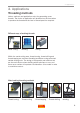
2. Applications 2. Applications Threading methods Various methods and applications exist for generating screw threads. The choice of application will be based on the time taken to produce the thread and the level of thread precision required. Different ways of making threads Metal cutting Molding Rolling Within the metal cutting area, thread turning, thread milling and thread tapping are common threading techniques using cemented carbide cutting tools.
2. Applications Thread milling vs. thread turning This application guide focuses on thread turning and thread milling products and application techniques. Each technique has its own advantages in certain situations.
2. Applications Insert types Three main types of threading principle can be used to produce a thread. The different technical and economic arguments for each insert are the main guide in the choice of application.
2. Applications Full profile inserts – first choice for high quality thread forms The most common insert type, used to form a complete thread profile, including the crest. • Ensures correct depth, bottom and top profile for a stronger thread • Extra stock should be 0.03 – 0.07 mm (0.001 – 0.
2. Applications Multi-point inserts – productive, economic threading in mass production Multi-point inserts are similar to full profile-, but have more than one insert point (two pointed inserts give double productivity, three pointed insert give triple etc.) Stable conditions are needed due to increased cutting forces as the cutting edge has a longer contact length.
2. Applications – Thread turning Thread turning Thread turning is the most common method of producing threads. The many tooling systems offered by Sandvik Coromant cover internal and external applications and make it possible to produce threads of all sizes and profiles, across all segments of the engineering industry.
2. Applications – Thread turning Insert geometries Selecting the correct insert geometry is important in threading, especially in machines where there is limited supervision. Here, geometry A offers consistent tool life and quality and is the first choice for most applications, while geometry F is sharper, reducing cutting forces. The chip-forming geometry C enables more continuous and unsupervised machining, free from sudden stoppages. This results in predictable tool life, and more active machining time.
2. Applications – Thread turning Insert geometries MC No. CMC No. P P1.1.Z.AN P2.1.Z.AN P2.5.Z.HT P3.1.Z.HT 01.1 02.1 02.2 03.21 M M5.0.Z.AN M1.0.Z.AQ M3.1.Z.AQ 05.11 05.21 05.51 K K1.1.C.NS K2.2.C.UT K3.1.C.UT 07.2 08.2 09.1 N N1.2.Z.UT N3.2.C.UT 30.11 33.2 S S1.0.U.AN S2.0.Z.AG S4.2.Z.AN 20.11 20.22 23.
2. Applications – Thread turning Infeed Infeed method dictates how the insert is applied to the workpiece to create the thread form. The three common infeed choices are modified-flank-, radial-, and incremental infeed.
2. Applications – Thread turning Radial infeed The most commonly-used infeed method and the only one possible on many non-CNC lathes. • Produces a stiff, V-shaped chip, which is difficult to form • Insert wear is even on both flanks • Suitable for fine pitches • Insert tip is exposed to high temperatures, restricting the possible infeed depth • Risk of vibration and poor chip control in large pitches Incremental infeed - for pitches larger than 5 mm (5 t.p.i.
2. Applications – Thread turning Successful chip control in thread turning Threading can present problems in machines where there is limited supervision. Chips can get trapped in chucks, often resulting in tool damage and lost machining time. To avoid these problems and achieve the best possible chip control, use modified-flank infeed, together with a C-geometry (chip-control) insert.
2. Applications – Thread turning Infeed depths per pass Decreasing depth per pass (constant chip area) • First choice, most common • First pass is deepest • More ‘balanced’ chip area • Even load on insert • Last pass 0.07 mm (.003 inch) Constant depth per pass • Each pass is of equal depth, regardless of number of passes • More demanding on the insert • Can improve chip control • Increases the required number of passes • Should not be used for pitches larger than 1.5 mm or 16 t.p.i.
2. Applications – Thread turning Number of passes and size of infeed per pass The recommended depths of cut for the different passes are shown in the table below. • These are recommended as starting values - the most suitable number of passes must be determined by trial and error. • Infeeds of less than 0.05 mm (0.002 inch) should be avoided • For Cubic Boron Nitride-tipped inserts, infeed should not exceed 0.10-0.12 mm (.004-.
2.
2. Applications – Thread turning External thread turning This is the most common thread turning method. It is often easier and less demanding on the tool and there are a number of different methods which can be used to achieve the desired results. Upside-down tool holders In many operations, it is beneficial to use a tool holder in an upside-down position, to help remove chips more effectively.
2. Applications – Thread turning Internal thread turning Internal threading is more demanding than external threading, due to the increased need to evacuate chips effectively. Chip evacuation, especially in blind holes, is helped by using lefthand tools for right-hand threads and vice versa (pull-threading). However, this also creates the greatest risk of insert movement.
2.
2. Applications – Thread turning Insert clearance angles Two types of angular clearance between the insert and thread are necessary for precise, accurate threading. These are: • Flank clearance • Radial clearance Radial clearance Flank clearance Flank clearance Cutting edge clearance between the sides of the insert and thread flank is essential to ensure that tool wear develops evenly, to give consistent, high quality threads.
2. Applications – Thread turning Selecting shims to tilt the insert for flank clearance Insert shims are used to give different tilts to the insert, so that the angle of insert inclination is the same as the helix of the thread. See table opposite for methods of selecting the correct insert shim.
2. Applications – Thread turning Methods for selecting the correct shim Two alternative ways to select the correct shim: A. Use the diagram, selecting shims. B. Use the formula to calculate the helix angle to choose the corresponding shim. A. Workpiece diameter and pitch influence inclination angles Lead (Pitch) mm Threads/inch mm inch Workpiece diameter For a pitch of 6 mm and a workpiece diameter of 40 mm, a 3° shim is required.
2. Applications – Thread turning Relationship between flank clearance, radial clearance and thread profile angle The smaller the thread profile and radial clearance angles, the smaller the flank clearance angle (see table below for flank clearance values when the correct shim, equal to the helix angle, is used). Please note that as the profile angle becomes smaller, it is more important to choose the correct shim.
2. Applications – Thread turning Radial clearance To give adequate radial clearance, inserts are tilted in the tool holder 10° or 15°. It is important to use internal inserts with internal tool holders, and vice-versa, to ensure that the correct thread form is achieved. Insert sizes 11, 16 and 22 mm (1/4, 3/8 and 1/2 inch) Insert size 27 mm (5/8 inch) Modified bars for small holes Internal boring bars can be modified to fit small holes and can be used in place of special tools.
2. Applications – Thread turning Multi-start threads Threads with two or more parallel thread grooves require two or more starts. The lead of this type of thread will then be twice that of a single-start screw. The lead increases relative to the pitch by a multiple equal to the number of starts. On a single-start thread, the lead and the pitch are equal; on a double start- the lead is twice the pitch, on a triple start- the lead is three times the pitch etc.
2. Applications – Thread turning Insert nose radius and tool life The nose radius is the smallest point on the insert and the most liable to break under the extreme pressure of a threading operation. Nose radii differ considerably for different insert types and consideration should be made to the cutting speed and number of passes in order to optimize performance and machining security. NPT and NPTF inserts have the smallest nose radii within the standard range.
2. Applications – Thread turning Insert tool life Careful observation of the insert after threading will allow you to achieve optimum results regarding tool life, cutting speed and thread quality. The main points to consider are: • When thread turning or thread milling at low speed, the main problem is builtup edge. To solve this, increase cutting speed • When thread turning at high speed, plastic deformation of the tip is the main problem.
2. Applications – Thread turning Thread deburring Burrs which appear at the start of the thread can cause problems and should be removed. This is especially important, for example, in the hydraulics and food processing industry where tolerance and quality demands are high. Burrs tend to form at the start of a thread before the insert creates the full profile, mostly in diffficult stainless steels and duplex materials - thread deburring is achieved with standard turning tools (mainly CoroCut inserts).
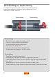
2. Applications – Thread milling Thread milling Thread milling produces threads with the circular ramping movement of a rotating tool. Here, the lateral movement of the tool in one revolution creates the thread pitch. Although not as widely used as thread turning; thread milling achieves high productivity in certain applications and offers an advantageous alternative to thread tapping.
2. Applications – Thread milling Benefits of thread milling vs. tapping When deciding on the choice of threading method, the benefits of thread milling over thread tapping should be considered.
2.
2. Applications – Thread milling Thread milling – main considerations To achieve the best results in a thread milling operation, always consider the following points. - Choice of cutting diameter A smaller cutting diameter will help to achieve higher quality threads. - Tool path is important • Tool path will give right or left hand threads, using down- or upmilling • Always engage and retract the thread mill in a smooth path, i.e.
2. Applications – Thread milling Choice of cutting diameter The cutter engagement will create a minute form error on the root of the thread profile. In internal applications, the relationship between threading diameter, cutting diameter and pitch will affect the true radial depth of cut, ae eff, which becomes much larger than the chosen radial depth of cut. A larger true ae will increase the deviation in the root of the thread.
2. Applications – Thread milling Tool path Thread milling requires machine tools which are capable of simultaneous movements on the X, Y and Z axes. The thread diameter is determined by the X and Y axis, while pitch is controlled by the Z axis. Z Pitch Y Right-hand internal threads All cutters are initially positioned as close as possible to the bottom of the hole, and then move anticlockwise in an upwards direction to ensure that down milling is achieved.
2. Applications – Thread milling Down milling and up milling Down milling is when the tool is fed in the direction of tool rotation and is the preferred method of application - when machine tool, fixture and workpiece will allow. Chip thickness decreases from the start of cut, until reaching zero at the end, which stops the edge rubbing and burning against the surface before it is engaged into cut. In up milling, the feed direction of the cutting tool is opposite to its rotation.
2. Applications – Thread milling Feed per tooth To avoid feed marks on the component surface, feed per tooth should not exceed 0.15 mm/tooth (.006 inch/tooth), therefore a small hex value is needed. Always calculate the correct feed required by machine software The feed value always depends on the hex value which corresponds with the peripheral feed rate, however many machines require a tool centre feed (vf).
2. Applications – Thread milling Wet or dry machining Machining dry is always recommended as cutting fluid emphasizes temperature variations at entry and exit, creating thermal cracks. Cutting fluid can be beneficial on certain occasions, such as when finishing stainless steels/aluminium, machining HRSA or machining cast iron (to reduce toxic dust). However, it is most beneficial to evacuate chips using compressed air.
2. Applications – Thread milling External threading with milling tools. All thread milling inserts are designed for internal threads, however CoroMill 327 and CoroMill 328 inserts can also be used for external threading. Consider the size of insert nose radius for the two operations, as a larger nose radius needs to be chosen for the external thread (internal - pitch/8, external - pitch/4). Thread root sizes differ slightly for internal and external threads. In the example below, a 2 mm (.
3. Products - thread turning 3. Products Thread turning The turning of threads is a common operation, with a wide range of systems available to help achieve high standards of productivity and effectiveness. Thread turning tools can be separated into two main areas - tools for external- and internal threading. External thread turning External systems: CoroThread® 266 T-Max Twin-Lock® CoroCut® XS Thread diameter T-Max Twin-Lock® CoroThread® 266 CoroCut® XS 0.2 32 46 2.0 10 8.0 5 3 mm t.p.i.
3. Products - thread turning Internal thread turning Internal systems: CoroThread® 266 T-Max Twin-Lock® CoroCut® MB CoroTurn® XS T-Max Twin-Lock® CoroThread® 266 CoroTurn® XS CoroCut® MB ≥ 4 mm .157 inch 4 .157 10 .393 ≥ 60 mm 2.362 inch ≥ 12 mm .472 inch ≥ 10 mm .393 inch 12 .472 60 2.362 Min.
3. Products - thread turning CoroThread® 266 – external and internal threading The first choice, indexable insert threading tool. Inserts are located on a guide rail on the shim, for high stability and precise, predictable machining. • First choice system for all thread turning • Large assortment of internal and external tools • High stability • Easy edge-indexing capability • Easy insert mounting • Reduced downtime Insert sizes iC l iC l mm inch mm inch 6.350 1/4 11* .039* 9.525 3/8 16 .
3. Products - thread turning The unique guide-rail interface between the insert and tip seat eliminates insert movement caused by cutting force variation. CoroThread 266 therefore provides accurate and repeatable thread profiles as a result of rigid insert stability. Insert with slots for rail guide Shim with rail guide The insert-rail support system solves the problem of insert movement, which is often caused by substantial forward- and reverse cutting forces when entering and exiting the thread.
3. Products - thread turning Assortment - CoroThread® 266 VW – VM MM – UN WH – NT V-profile 55° (VW) Pitch: 28 – 4 t.p.i. Metric 60° (MM) Pitch: 0.5 – 6 mm Whitworth 55° (WH) Pitch: 28 – 4 t.p.i. V-profile 60° (VM) Pitch: 1 – 6 mm 24 – 4 t.p.i. UN 60° (UN) Pitch: 32 – 4 t.p.i. NPT 60° (NT) Pitch: 27 – 8 t.p.i. Type of insert A (all-round) F (sharp) C (chip breaking) Multi-point PT – NF BSPT 55° (PT) Pitch: 28 – 8 t.p.i. RN Round 30° (RN) Pitch: 10 – 4 t.p.i.
3. Products - thread turning CoroThread® 266 – grade recommendations Two unique grades offer the chance to boost threading performance with CoroThread 266. GC1125 Optimized for steel and cast-iron threading with high wear resistance. Can also be applied in ISO M, -N and -S materials GC1135 Optimized for stainless steel and HRSA and the best choice for sharp geometries, with high toughness and safe edges. Can also be applied in ISO P and -K materials.
3. Products - thread turning CoroThread® 266 – tool holder assortment The wide CoroThread 266 programme is available in the following tool holder versions.
3. Products - thread turning Tolerance classes with CoroThread® 266 CoroThread 266 turns threads in the following tolerance classes, in metric, inch and Whitworth systems by concentrating only on the pitch diameter.
3. Products - thread turning Dampened 4C Silent Tools bars – vibration-free internal threading For internal threading operations - where radial forces are higher than in external threading - the recommended bar type is 570-4C. 570-4C bars are developed primarily for internal threading applications. The combination of Silent Tools adaptor and flank infeed is recommended for overhangs of up to 5 x D, to combat axial and radial cutting forces.
3. Products - thread turning QS holding system for sliding head machines – external threading The QS holding system fits in the sliding head machine tool post to provide a quick-changing alternative to conventional gang tool racks. Tool holders are available for threading, turning and parting and grooving.
3. Products - thread turning CoroCut® XS – external threading For precision threading in small part machining, up to 32 mm (1.26 inch) diameter. CoroCut XS is used ideally where the tool is close to the shoulder of the workpiece and in sliding head machines. Also for parting, grooving and turning. • All inserts fit into the same tool holder • Easy indexing and good accessibility when changing inserts • Sharp cutting edges • Low cutting forces All inserts fit into CoroCut XS shank holders.
3. Products - thread turning Tool holder recommendations All inserts fit into the same tool holder and also with CoroTurn SL cutting heads. Good accessibility is achieved when changing inserts, as the insert screw can be reached from both sides – to reduce downtime. Assortment - CoroCut® XS VM V-profile 60° (VM) Pitch: 0.2 – 2 mm 12 – 80 t.p.i.
3. Products - thread turning CoroTurn® XS – internal precision threading CoroTurn XS has an insert in the form of a rod, mounted in an easily-indexable adaptor. The tool is intended for precision machining in hole diameters from 0.3 – 12 mm (.012 – .412 inch), with extremely sharp cutting edges giving good results at low feeds. Threading inserts are available for UN, Whitworth, metric, TR and NPT thread forms.
3. Products - thread turning Assortment - CoroTurn® XS VM V-profile 60° (VM) Pitch: 0.5 – 1.5 mm 48 – 16 t.p.i. MM – UN Metric: 60° (MM) Pitch: 0.5 – 2.0 mm UN 60° (UN) Pitch: 32 – 16 t.p.i. Type of insert F-sharp Geometry F-sharp Grade ISO GC1025 (VM, MM-UN) CB7015 (VM) WH – NT AC – SA Whitworth 55° Pitch: 28 – 19 t.p.i. ACME 29° (AC) Pitch: 1.5 – 3 mm NPT 60° (NT) Pitch: 27 – 18 t.p.i. STUB-ACME 29° (SA) Pitch: 16 – 8 t.p.i.
3. Products - thread turning CoroCut® MB – internal threading CoroCut MB has front-mounted exchangeable inserts for internal machining in hole diameters from 10 – 25 mm (.394 – .984 inch). Its sharp cutting edges give good results at low feeds. Boring bars are available in steel and carbide, with through coolant. The bars are to be used together with EasyFix clamping in up to 6 x bar diameter overhang.
3. Products - thread turning Assortment - CoroCut® MB VM V-profile 60° (VM) Pitch: 0.5 – 2.5 mm 32 – 10 t.p.i. MM – UN Metric: 60° (MM) Pitch: 0.5 – 2.5 mm UN 60° (UN) Pitch: 18 – 14 t.p.i. Type of insert Geometry F-geometry Grade ISO F (sharp) GC1025 (VM, MM-UN) CB7015 (MM) WH – NT AC – SA Whitworth 55° Pitch: 19 – 11 t.p.i. ACME 29° (AC) Pitch: 16 – 8 t.p.i. NPT 60° (NT) Pitch: 18 – 14 t.p.i. STUB-ACME 29° (SA) Pitch: 16 – 8 t.p.i.
3. Products - thread turning T-Max Twin-Lock® – internal and external threading Designed for threading in high volume areas of the oil and gas industry. Examples of applications are tubing, casing and coupling production. The system also covers connection threads, where indexing accuracy, insert edge reliability and repeatability are essential. • Productive threading with multi-tooth inserts • Minimum hole diameter 60 mm (.2.
3. Products - thread turning CoroTurn® SL cutting heads – internal and external threading SL (serration lock) exchangeable cutting heads enable a versatile range of cutting units to be built from a manageable inventory. The tools can be attached to a CoroTurn SL boring bar or adaptor to provide added tooling flexibility, with performace similar to a solid tool regarding deflection and vibration. For threading, exchangeable cutting heads are available for CoroThread® 266 and T-Max® Twin Lock.
3. Products - thread turning Extended offer Due to the wide range of thread styles with different shapes and pitches, Sandvik Coromant have prepared special insert types for CoroThread 266, outside the standard range. These inserts ensure high thread quality, productivity and flexibility and are available for the following thread designations: CoroThread 266 threading inserts 11 – 27 mm (1/4” – 5/8”) General threading profiles: • MJ, ISO5855 • UNJ, ISO3166 (internal) • American Buttress, ANSI B1.
3. Products - thread milling Thread Milling The main options for thread milling using Sandvik Coromant tools are single-point threading with CoroMill® 327 and CoroMill® 328, and multi-point threading with CoroMill® Plura. CoroMill® Plura CoroMill® 327 CoroMill® 328 Pitch 0.7 – 3 mm 28 – 10 t.p.i. 1 – 4.5 mm 24 – 5 t.p.i. 1.5 – 6 mm 16 – 4 t.p.i. Cutter dia (Dc), mm (inch) 3.2 – 19 (.189 – .783) 11.7 – 21.7 (.461 – .854) 39 – 80 (1.535 – 2.
3. Products - thread milling CoroMill® 327 and CoroMill® 328 – Single-point threading CoroMill tools offer many advantages for thread milling. For singlepoint threading, use CoroMill 327 and CoroMill 328.
3. Products - thread milling CoroMill® 327 Designed for holes over 12 mm (.472 inch), CoroMill 327 offers inserts for metric, UN and Whitworth threads. The front-mounted inserts are positioned in grooves for secure mounting, and through-tool coolant aids chip evacuation, giving secure and continuous performance. CoroMill 327 is available in versatile grade GC1025, for all material types.
3. Products - thread milling 1. V-profile 60° *2. Full profile 60° 1. 2. 3. Full profile 55° (Whitworth) 3. * Compared to full profile turning inserts, full profile (60°) milling inserts top only one side of the thread form. Assortment - CoroMill® 327 MM VM Metric 60° (MM) Pitch: 1.50 – 4.50 mm V-profile 60° (VM) Pitch: 1.00 – 4.50 mm 24 – 5 t.p.i. 21.7 (.854) 3 Diameter (Dc) mm, (inch) No. of teeth (zn) Grade hex Max rec. fz ISO 0.05 .002 0.15 .006 mm inch mm inch 11.7 – 21.7 (.461 – .
3. Products - thread milling CoroMill® 328 For larger holes over 39 mm (1.535 inch), CoroMill 328 offers in serts for metric and UN threads. Inserts are pocket-mounted for safe and stable positioning, with 3 cutting edges per insert and high-pitch cutter bodies. CoroMill 328 is available in versatile grade GC1025, for all material types. Weldon, arbor and bore with keyway mounting. Assortment - CoroMill® 328 VM V-profile 60° (VM) Pitch: 1.50 – 6.00 mm 16 – 4 t.p.i. Diameter (Dc) mm, (inch) No.
3. Products - thread milling CoroMill® Plura – Multi-point threading CoroMill Plura solid carbide thread mills produce different threads of the same pitch with one tool. Threads are milled in one pass and this multi-point tool gives a true full-profile thread form, with 60° metric, UNC/UNF and NPT/NPTF options available CoroMill Plura is designed for smaller thread sizes in diameters down to 3.2 mm (.126 inch) and in two optimized grade choices, with or without through coolant.
3. Products - thread milling Assortment - CoroMill® Plura MM UNC/UNCF Metric 60° (MM) Pitch: 0.7 – 3.0 mm UN 60° (UN) 28 – 10 t.p.i. NPT/NPTF NPT/NPTF 60° 27 – 11.5 t.p.i. Type of insert Full-profile Diameter (Dc) mm, (inch) No. of teeth (zn) 3.2 – 19 3–5 ISO (.189 – .551) 3–5 GC1620 GC1630 (.311 – .
3. Products Grade information The wide range of carbide threading grades from Sandvik Coromant offers high productivity for many materials and applications. Once you have selected the most suitable tool for the threading operation, simply choose the available grade which most closely matches your application requirements.
3. Products GC1125 Coating: PVD TiCrAlN Tools: CoroThread 266. T-Max Twin-Lock PVD grade for ISO P, -M, -K, -N materials. Combines the superior wear resistance of a coated grade with the edge sharpness and toughness of an uncoated grade. Optimized for steel threading and for speeds from medium to high. GC1125 makes it possible to decrease the number of passes or increase cutting speed, compared to CoroThread 266 GC1020.
3. Products GC4125 Coating: PVD TiAlN Tools: T-Max Twin-Lock Thick, PVD coating which is more wear resistant than GC1020 – and enables higher cutting speeds, especially in the ISO P area. GC1025 Coating: PVD TiAlN coating (thin) Tools: CoroCut XS, CoroCut MB, CoroTurn XS, CoroMill 327 and CoroMill 328. All-round grade for all materials and applications, with thin PVD TiAIN coating ideal for sharp edges. H13A Coating: Uncoated Tools: CoroCut XS, CoroThread 266 Uncoated grade for all materials.
3. Products GC1105 Coating: PVD TiAlN coating (thin) Tools: CoroCut XS First-choice grade for the ISO M and -S area. A hard substrate with a thin coating ideal for sharp edges makes it first choice for threading in medical components. Also with high plastic deformation resistance. GC1620 Coating: PVD TiAlN (thin) Tools: CoroMill Plura CoroMill Plura grade for semi-finishing to finishing operations demanding wear resistance, especially in dry machining.
4. Troubleshooting 4. Troubleshooting Careful observation of the insert/cutting edge after machining can help to optimize results regarding tool life, thread quality and cutting speed. Use this list of causes and solutions to different forms of insert wear as a reference for successful threading.
4. Troubleshooting – Thread turning Problem Cause Solution • Wrong turned diameter prior to threading • Turn to correct diameter before threading operation (0.03 – 0.07 mm, .001 – .003 inch) radially larger than max. diameter for thread Insert breakage • Infeed series too tough • Wrong grade • Poor chip control • Incorrect centre height • Increase number of infeeds.
4. Troubleshooting – Thread turning Problem Cause Solution Abnormal flank wear • Incorrect method for flank infeed • Insert inclination angle does not agree with the lead angle of the thread • Change method of flank infeed for Fand A-geometry to 3 - 5° from flank. For C-geometry to 1° from flank • Change shim to obtain correct angle of inclination Poor surface on one flank of thread.
4.
4.
4. Troubleshooting – Thread milling Thread milling Problem Cause Solution Chipping • The part of the cutting edge which is not in cut is damaged by chip hammering, leading to poor surface and excessive flank wear • Increase cutting speed • Reduce feed at the beginning of the cut • Improve stability • Increase number of infeed passes • Use a full-profile insert Built-up edge (B.U.E) Poor surface finish and cutting edge frittering when the built-up edge is torn away.
4.
4. Troubleshooting – Thread milling Problem Cause Solution Rapid wear causing poor surface finish or out of tolerance. • Reduce cutting speed, vc Flank wear • Increase feed, fz • Cutting speed too high • Insufficient wear resistance • Feed, fz, too low Excessive wear causing short tool life.
4.
4.
5. Technical reference 5. Technical reference CoroThread® 266 Thread turning cutting speed recommendations, metric Hardness Brinell Grades GC1125 ISO MC No. P CMC No. P1.1.Z.AN 01.1 P2.1.Z.AN 02.1 P3.0.Z.AN 03.21 M P5.0.Z.AN 05.11 M1.0.Z.AQ 05.21 M3.1.Z.AQ 05.51 K K1.1.C.NS 07.2 K2.2.C.UT 08.2 K3.1.C.UT 09.1 N N1.2.Z.UT 30.11 N1.3.C.UT 30.21 N3.2.C.UT 33.2 S S1.0.U.AN 20.11 S2.0.Z.AG 20.22 S4.2.Z.AN 23.21 H H1.3.Z.HA 04.1 H1.3.Z.HA 04.1 Material Steel Unalloyed C = 0.1–0.
5. Technical reference CoroThread® 266 Thread turning cutting speed recommendations. inch Hardness Brinell Grades GC1125 ISO MC No. P CMC No. P1.1.Z.AN 01.1 P2.1.Z.AN 02.1 P3.0.Z.AN 03.21 M P5.0.Z.AN 05.11 M1.0.Z.AQ 05.21 M3.1.Z.AQ 05.51 K K1.1.C.NS 07.2 K2.2.C.UT 08.2 K3.1.C.UT 09.1 N N1.2.Z.UT 30.11 N1.3.C.UT 30.21 N3.2.C.UT 33.2 S S1.0.U.AN 20.11 S2.0.Z.AG 20.22 S4.2.Z.AN 23.21 H H1.3.Z.HA 04.1 H1.3.Z.HA 04.1 Material Steel Unalloyed C = 0.1–0.
5. Technical reference CoroMill® 327 and CoroMill® 328 Thread milling cutting speed recommendations with grade GC1025, metric Specific cut- Hardness ting force kc Brinell ISO MC No. P CMC No. P1.1.Z.AN 01.1 P2.1.Z.AN 02.1 P3.0.Z.AN 03.21 M P5.0.Z.AN 05.11 M1.0.Z.AQ 05.21 M3.1.Z.AQ 05.51 K K1.1.C.NS 07.2 K2.2.C.UT 08.2 K3.1.C.UT 09.1 N N1.2.Z.UT 30.11 N1.3.C.UT 30.21 N3.2.C.UT 33.2 S S1.0.U.AN 20.11 S2.0.Z.AG 20.22 S4.2.Z.AN 23.21 H 88 H1.3.Z.HA 04.1 Material Steel Unalloyed C = 0.1–0.
5. Technical reference CoroMill® 327 and CoroMill® 328 Thread milling cutting speed recommendations with grade GC1025, inch Specific cut- Hardness ting force kc Brinell ISO MC No. P CMC No. P1.1.Z.AN 01.1 P2.1.Z.AN 02.1 P3.0.Z.AN 03.21 M P5.0.Z.AN 05.11 M1.0.Z.AQ 05.21 M3.1.Z.AQ 05.51 K K1.1.C.NS 07.2 K2.2.C.UT 08.2 K3.1.C.UT 09.1 N N1.2.Z.UT 30.11 N1.3.C.UT 30.21 N3.2.C.UT 33.2 S S1.0.U.AN 20.11 S2.0.Z.AG 20.22 S4.2.Z.AN 23.21 H H1.3.Z.HA 04.1 Material Steel Unalloyed C = 0.1–0.
5. Technical reference CoroMill® Plura Thread milling cutting data recommendations. metric Material Thread mill Dimensions, mm HRC Low alloy steel 02.2 300 High alloy steel 03.21 450 M K Stainless steel 05.11 200 05.21 200 05.51 230 Malleable cast iron 07.2 Nodular cast iron 08.2 Grey cast iron 09.1 N S Aluminium 30.11 60 30.21 95 33.2 150 Heat resistant alloys 20.11 200 Titanium alloys 20.22 300 23.21 H 90 300 Hardened steel 04.1 55 04.
5. Technical reference CoroMill® Plura Thread milling cutting data recommendations. inch Material Thread mill HRC Low alloy steel 02.2 300 High alloy steel 03.21 450 M K Stainless steel 05.11 200 05.21 200 05.51 230 Malleable cast iron 07.2 Nodular cast iron 08.2 Grey cast iron 09.1 N S Aluminium 30.11 60 30.21 95 33.2 150 Heat resistant alloys 20.11 200 Titanium alloys 20.22 300 23.21 H 300 Hardened steel 04.1 55 04.
5. Technical reference Programming Modern machine tools use computer numerical control (CNC) methods to produce complex parts in a consistent and automated manner. This capability is especially important when producing threads. CNC machines can process 2-dimensional and 3-dimensional shapes using their coordinate axes, with each machine typically having 3-axis (X, Y, Z) - though machines with up to 12-axes do exist.
5. Technical reference Example ISO longhand code (lathe) T0101 (THREADING TOOL) G97 S2103 M3 G0 X26.0 Z8.5 M8 G0 X23.623 Z4.5 G32 Z-26.5 F2.0 G0 X26.0 G0 Z4.404 G0 X23.083 G32 Z-26.5 F2.0 G32 is the command for the threading movement in the machine. This code can differ depending of the CNC system (check your machine manual to confirm). If the start point for the threading operation varies in the z-axis, the thread should be programmed with flank infeed.
5. Technical reference CoroMill® Plura CoroMill Plura has an individual radius programming value (RPRG) marked on the shank of the tool. The RPRG value indicates each cutter’s exact pitch diameter and the radius required for optimum thread quality. The RPRG value is normally entered into the tool memory offset. Using the RPRG will prevent the first thread from being too large, as long as the operational conditions are good. Climb milling Cutting speed vc 127 m/min 5000 inch/min Feed per tooth 0.
5. Technical reference G00 Z-21.000 Move to required depth on centerline of the pre-drilled hole G41 D... G01 X0.000 Y6.000 F994 Set approach path for entry loop G03 X0.000 Y-8.000 Z-20.000 10.000 J-7.000 F121 Move to the contour starting point G03 X0.000 Y-8.000 Z-18.000 10.000 J8.000 F249 Thread milling G03 X0.000 Y-6.000 Z-17.000 10.000 J7.000 Move clear of the contour G40 G01 X0.000 Y0.000 Re-set to centerline G00 Z2.000 Repeat this program for CoroMill 327/CoroMill 328.
5. Technical reference Thread turning infeed recommendations ISO Metric (MM), external Pitch, mm 0.50 0.75 No. of infeeds 1 2 3 4 5 6 7 8 9 10 11 12 13 14 15 16 Total infeed Unit mm inch mm inch mm inch mm inch mm inch mm inch mm inch mm inch mm inch mm inch mm inch mm inch mm inch mm inch mm inch mm inch mm inch 1.00 Radial infeed per pass 0.10 0.16 0.16 .004 .006 .006 0.09 0.15 0.15 .004 .006 .006 0.08 0.12 0.14 .003 .005 .006 0.07 0.07 0.12 .003 .003 .005 0.08 .003 0.34 .013 0.50 .020 0.65 .
5. Technical reference Thread turning infeed recommendations ISO Metric (MM), internal Pitch, mm 0.50 0.75 No. of infeeds 1 2 3 4 5 6 7 8 9 10 11 12 13 14 15 16 Total infeed Unit mm inch mm inch mm inch mm inch mm inch mm inch mm inch mm inch mm inch mm inch mm inch mm inch mm inch mm inch mm inch mm inch mm inch 1.00 Radial infeed per pass 0.10 0.15 0.15 .004 .006 .006 0.09 0.14 0.14 .004 .005 .006 0.08 0.12 0.13 .003 .005 .005 0.07 0.07 0.12 .003 .003 .005 0.08 .003 0.34 .013 0.48 .019 0.63 .
5. Technical reference Thread turning infeed recommendations ISO inch (UN), external Pitch, t.p.i. 32 28 No. of infeeds 1 2 3 4 5 6 7 8 9 10 11 12 13 14 15 16 Total infeed Unit mm inch mm inch mm inch mm inch mm inch mm inch mm inch mm inch mm inch mm inch mm inch mm inch mm inch mm inch mm inch mm inch mm inch 24 20 Radial infeed per pass 0.17 0.15 0.18 0.18 .007 .006 .007 .007 0.16 0.14 0.16 0.17 .006 .005 .006 .007 0.13 0.13 0.15 0.15 .005 .005 .006 .006 0.08 0.11 0.13 0.14 .003 .004 .005 .006 0.
5. Technical reference Thread turning infeed recommendations ISO inch (UN), internal Pitch, t.p.i. 32 28 No. of infeeds 1 Unit mm inch mm 2 inch mm 3 inch mm 4 inch mm 5 inch mm 6 inch mm 7 inch mm 8 inch mm 9 inch mm 10 inch mm 11 inch mm 12 inch mm 13 inch mm 14 inch mm 15 inch mm 16 inch mm Total infeed inch 24 20 Radial infeed per pass 0.16 0.14 0.16 0.16 .006 .005 .006 .006 0.14 0.13 0.15 0.15 .006 .005 .006 .006 0.13 0.12 0.14 0.14 .005 .005 .006 .006 0.08 0.11 0.12 0.13 .003 .004 .005 .005 0.
5. Technical reference Thread turning infeed recommendations Whitworth (WH), external and internal No. of infeeds 1 2 3 4 5 6 7 8 9 10 11 12 13 14 15 16 Total infeed Unit mm inch mm inch mm inch mm inch mm inch mm inch mm inch mm inch mm inch mm inch mm inch mm inch mm inch mm inch mm inch mm inch mm inch Pitch, t.p.i. 28 26 20 19 Radial infeed per pass 18 16 14 12 11 10 9 8 7 6 5 0.31 .012 0.30 .012 0.29 .012 0.28 .011 0.28 .011 0.27 .010 0.25 .010 0.24 .010 0.23 .009 0.22 .009 0.20 .008 0.
5. Technical reference Thread turning infeed recommendations NPT (NT), external and Internal Round 30° Din405 (RN),external Pitch, t.p.i. 10 No. of infeeds 1 2 3 4 5 6 7 8 9 10 11 12 13 14 Total infeed Unit mm inch mm inch mm inch mm inch mm inch mm inch mm inch mm inch mm inch mm inch mm inch mm inch mm inch mm inch mm inch 8 Radial infeed per pass 0.21 0.21 .008 .008 0.20 0.20 .008 .008 0.19 0.19 .007 .008 0.18 0.19 .007 .007 0.16 0.18 .006 .007 0.15 0.17 .006 .007 0.13 0.15 .005 .006 0.08 0.14 .
5. Technical reference Thread turning infeed recommendations ACME (AC), external Pitch, t.p.i. 16 No. of infeeds 1 2 3 4 5 6 7 8 9 10 11 12 13 14 15 16 17 18 19 Total infeed Unit mm inch mm inch mm inch mm inch mm inch mm inch mm inch mm inch mm inch mm inch mm inch mm inch mm inch mm inch mm inch mm inch mm inch mm inch mm inch mm inch 14 Radial infeed per pass 0.22 0.20 .009 .008 0.20 0.19 .008 .008 0.19 0.18 .007 .007 0.17 0.17 .007 .007 0.14 0.15 .006 .006 0.08 0.13 .003 .005 0.08 .003 0.99 .
5. Technical reference Thread turning infeed recommendations ACME (AC), internal Pitch, t.p.i. 16 No. of infeeds 1 2 3 4 5 6 7 8 9 10 11 12 13 14 15 16 17 18 19 Total infeed Unit mm inch mm inch mm inch mm inch mm inch mm inch mm inch mm inch mm inch mm inch mm inch mm inch mm inch mm inch mm inch mm inch mm inch mm inch mm inch mm inch 14 Radial infeed per pass 0.22 0.21 .009 .008 0.21 0.20 .008 .008 0.19 0.19 .008 .007 0.17 0.17 .007 .007 0.14 0.16 .006 .006 0.08 0.13 .003 .005 0.08 .003 1.02 .
5. Technical reference Thread turning infeed recommendations Stub-ACME (SA), external and Internal Pitch, t.p.i. 16 No. of infeeds 1 2 3 4 5 6 7 8 9 10 11 12 13 14 15 Total infeed Unit mm inch mm inch mm inch mm inch mm inch mm inch mm inch mm inch mm inch mm inch mm inch mm inch mm inch mm inch mm inch mm inch 14 Radial infeed per pass 0.18 0.20 .007 .008 0.16 0.18 .006 .007 0.15 0.17 .006 .007 0.13 0.14 .005 .006 0.08 0.08 .003 .003 0.70 .028 0.77 .030 12 10 8 6 5 4 3 0.18 .007 0.17 .007 0.
5. Technical reference Thread turning infeed recommendations Trapezoidal (TR), external and Internal Pitch, mm 1.5 No. of infeeds 1 2 3 4 5 6 7 8 9 10 11 12 13 14 15 16 17 18 19 Total infeed Unit mm inch mm inch mm inch mm inch mm inch mm inch mm inch mm inch mm inch mm inch mm inch mm inch mm inch mm inch mm inch mm inch mm inch mm inch mm inch mm inch 2 Radial infeed per pass 0.22 0.22 .009 .009 0.21 0.21 .008 .008 0.19 0.20 .008 .008 0.17 0.19 .007 .007 0.14 0.17 .006 .007 0.08 0.16 .003 .006 0.13 .
5. Technical reference Thread turning infeed recommendations MJ, external UNJ, external Pitch, t.p.i. 32 28 No. of infeeds 1 2 3 4 5 6 7 8 9 10 11 12 Total infeed Unit mm inch mm inch mm inch mm inch mm inch mm inch mm inch mm inch mm inch mm inch mm inch mm inch mm inch 24 20 Radial infeed per pass 0.16 0.14 0.16 0.16 .006 .005 .006 .006 0.14 0.13 0.15 0.15 .006 .005 .006 .006 0.13 0.12 0.14 0.14 .005 .005 .006 .006 0.08 0.11 0.12 0.13 .003 .004 .005 .005 0.08 0.08 0.12 .003 .003 .005 0.08 .
5. Technical reference Thread turning infeed recommendations API thread forms No. of infeed Insert Pitch Unit Total infeed Radial infeed per pass 1 2 3 4 5 6 7 8 9 10 11 12 13 14 15 API 60° V-0.038R 266RG-22V381A0402E 4 t.p.i. 266RL-22V381A0402E 4 t.p.i. 266RG-22V381A0403E 4 t.p.i. 266RL-22V381A0403E 4 t.p.i. mm inch mm inch mm inch mm inch 0.36 .014 0.36 .014 0.36 .014 0.36 .014 0.35 .014 0.35 .014 0.34 .013 0.34 .013 0.33 .013 0.33 .013 0.33 .013 0.33 .013 0.32 .013 0.32 .013 0.
5. Technical reference Thread turning infeed recommendations Multi-point ISO Metric (MM) ISO inch (UN) External Pitch, mm 1.00 1.50 External No. of infeeds 1 2 3 4 Total infeed Internal No. of infeeds 1 2 3 4 Total infeed 2.00 Unit mm inch mm inch mm inch mm inch mm inch Radial infeed per pass 0.34 0.36 0.47 .013 .014 .019 0.31 0.33 0.46 .012 .013 .018 0.26 0.33 .010 .013 Unit mm inch mm inch mm inch mm inch mm inch Radial infeed per pass 0.33 0.35 0.46 .013 .014 .018 0.30 0.32 0.42 .012 .013 .
5. Technical reference Thread turning infeed recommendations, CoroCut® XS ISO Metric (MM) Unit mm inch mm inch mm inch mm inch mm inch mm inch mm inch mm inch mm inch mm inch mm inch mm inch mm inch Pitch, mm 0.20 0.25 0.30 0.35 0.40 0.45 0.50 0.75 1.00 1.25 1.50 1.75 2.00 ISO inch (UN) Total infeed 0.12 .005 0.15 .006 0.18 .007 0.21 .008 0.25 .010 0.28 .011 0.29 .011 0.45 .018 0.60 .024 0.74 .029 0.90 .035 1.06 .042 1.21 .
5. Technical reference Thread turning infeed recommendations, CoroTurn® XS ISO Metric (MM) Unit mm inch mm inch mm inch mm inch mm inch mm inch mm inch mm inch mm inch Pitch, mm 0.50 0.70 0.75 0.80 1.00 1.25 1.50 1.75 2.00 ISO inch (UN) Total infeed 0.34 .013 0.43 .017 0.48 .019 0.53 .021 0.63 .025 0.77 .030 0.92 .036 1.05 .041 1.20 .047 nap 7 7 8 8 8 8 8 8 11 11 11 11 13 13 14 14 18 18 Unit mm inch mm inch mm inch mm inch mm inch mm inch mm inch mm inch Total infeed 0.64 .025 0.68 .027 0.71 .028 0.
5. Technical reference Thread turning infeed recommendations, CoroCut® MB ISO Metric (MM) Unit mm inch mm inch mm inch mm inch mm inch mm inch Pitch, mm 0.50 1.00 1.50 1.75 2.00 2.50 ISO inch (UN) Total infeed 0.34 .013 0.63 .025 0.92 .036 1.05 .041 1.20 .047 1.48 .058 nap 4 4 5 5 6 6 8 8 8 8 10 10 Whitworth (WH) Unit mm inch mm inch mm inch Pitch, t.p.i. 19 14 11 Pitch, t.p.i. 32 28 24 20 18 16 14 Total infeed 0.51 .020 0.58 .023 0.66 .026 0.78 .031 0.86 .034 0.96 .038 1.07 .
5. Technical reference External thread milling recommendations All values are based on the theoretical base profile to which tolerances are added CoroMill 327, metric Internal Pitch 1 Thread height, 5H/8 Root 0.54 0.13 1.5 0.81 1.75 External Insert 327Rxx-xx100VM-THx ar max 1.20 Nose radii 0.13 ar required 0.54 Root 0.25 0.19 327Rxx-xx100VM-THx 327R12-22150MM-TH 1.20 0.81 0.13 0.19 0.87 0.81 0.38 0.95 0.22 1.08 0.25 2.5 1.35 0.31 1.20 0.95 1.20 1.08 1.69 2.00 2.65 0.13 0.22 0.
5. Technical reference External thread milling recommendations All values are based on the theoretical base profile to which tolerances are added CoroMill 328, metric Internal External Pitch 1.5 1.75 2 Thread height, 5H/8 0.81 0.95 1.08 Root 0.19 0.22 0.25 Insert 328R13-150VM-TH 328R13-150VM-TH 328R13-150VM-TH ar max 2.11 2.11 2.11 Nose radii 0.19 0.19 0.19 ar required 0.81 0.97 1.14 Root 0.38 0.44 0.50 2.5 1.35 0.31 327R13-150VM-TH 2.11 0.19 1.46 0.63 3 1.62 0.38 327R13-150VM-TH 2.
5. Technical reference Formulas Use the following formulas as a reference for successful thread machining. Thread turning formulas Infeed (Manual formulas, when not using the Sandvik Coromant calculator) apx = ap √ nap - 1 √ Δap = Radial infeed X= Actual pass (in a series from 1 to nap) ap = Total depth of thread + extra stock nap = Number of passes = 1st pass = 0.
5. Technical reference Pitch 1.5 mm ap = 0.94 mm (.037 inch) nap = 6 1 = 0.3 2 =1 n = x-1 apx 1 = 0.94 apx 1 = .037 apx 2 = 0.94 apx 2 = .037 apx 3 = 0.94 apx 3 = .037 apx 4 = 0.94 apx 4 = .037 apx 5 = 0.94 apx 5 = .037 apx 6 = 0.94 apx 6 = .037 √5 √5 √5 √5 √5 √5 √5 √5 √5 √5 √5 √5 √ 0.3 = 0.23 1st pass, infeed = 0.23 mm = .009 inch √ 0.3 = .009 √ 1 = 0.42 √ 1 = .017 √ 2 = 0.59 √ 2 = .023 √ 3 = 0.73 √ 3 = .029 √ 4 = 0.
5. Technical reference Flank clearance depending on profile = arctan sin tan() 2 Radial clearance Flank clearance Tread profile Angle () Internal 15° () External 10° () Metric. UN Whitworth Trapezoidal ACME Buttress 60° 8.5° 6° 55° 7.5° 5° 30° 4° 2.5° 29° 4° 2.5° 10° / 3° 2° / 0.5° 2.5° / 0.5° Angle of insert inclination P d2 = arctan Multi-start threads If the thread has multi-starts, calculate the helix angle with this formula.
5.
5. Technical reference Inch/mm conversion table Conversion t.p.i. to pitch in mm Pitch in mm to t.p.i. t.p.i. Pitch mm Pitch mm t.p.i. 32 0.794 0.50 50.80 28 0.907 0.75 33.87 27 0.941 1.00 25.40 24 1.058 1.25 20.32 20 1.270 1.50 16.93 19 1.337 1.75 14.51 18 1.411 2.00 12.70 16 1.587 2.50 10.16 14 1.814 3.00 8.47 13 1.954 3.50 7.26 12 2.117 4.00 6.35 11.5 2.209 4.50 5.64 11 2.309 5.00 5.08 10 2.540 5.50 4.62 9 2.822 6.00 4.23 8 3.175 7.