SANRAD V-Switch User Manual MIG – 002 – 02 August 2004
Notice This manual contains information that is proprietary to SANRAD. No part of this publication may be reproduced in any form whatsoever without prior written approval by SANRAD.
Limited Warranty SANRAD warrants to the CUSTOMER that the hardware in the V-Switch to be delivered hereunder shall be free of defects in material and workmanship under normal use and service for a period of twelve (12) months following the date of shipment to the CUSTOMER.
relating to this Agreement and the V-Switch shall not exceed the sum paid to SANRAD for the purchase of the Product. In no event shall SANRAD be liable for any indirect, incidental, consequential, special, or exemplary damages or lost profits, even if SANRAD has been advised of the possibility of such damages. This Agreement shall be construed and governed in accordance with the laws of the State of Israel.
Safety Notices Read and understand the following notices before installing the V-Switch. The power plug must be accessible at all times because it serves as the main disconnecting vehicle. Unplug the V-Switch power cord before performing maintenance procedures. The V-Switch contains two power supply units. To disconnect the V-Switch completely, all power supply cords must be unplugged. Do not touch the power supplies when their power cords are connected.
User Notes SANRAD V-Switch User Manual
T Table of Contents CHAPTER 1: V-SWITCH ........................................................................ 15 V-SWITCH OVERVIEW ..................................................................................................... 16 ORDER OF OPERATIONS ................................................................................................. 17 MANUAL ORGANIZATION................................................................................................. 18 CLI - COMMAND LINE INTERFACE ...
RACK MOUNTING ........................................................................................................... 36 STORAGE PORT CONNECTIONS ....................................................................................... 37 NETWORK PORT CONNECTIONS ...................................................................................... 39 CONSOLE PORT CONNECTION......................................................................................... 40 MANAGEMENT PORT CONNECTION .............
Working with SCSI Storage Devices Maintaining Cluster Communications Enabling and Disabling Failover Further V-Switch Cluster Configurations Viewing V-Switch Neighbor Details 78 78 79 79 80 MANAGING A CLUSTER ................................................................................................... 81 CHAPTER 6: VOLUME CONFIGURATION .............................................. 83 INTRODUCTION TO VOLUME CONFIGURATION ...................................................................
COPYING A VOLUME (OFF-LINE COPY) .......................................................................... 139 SYNCHRONIZING A VOLUME .......................................................................................... 140 ADDING A CHILD TO A MIRROR (ON-LINE COPY) ............................................................ 141 CREATING A SNAPSHOT................................................................................................ 144 Viewing Snapshot Volumes 149 BREAKING A MIRROR ......
DISKS AND SUBDISKS ................................................................................................... 181 Discovering Storage Devices Renaming a Storage Device Removing a Storage Device Renaming a Subdisk Removing a Subdisk 181 182 183 183 183 CLUSTERS ...................................................................................................................
neighbor set neighbor show neighbor details neighbor remove cluster show cluster set cluster failover enable cluster failover disable ft show ft upload software ft download ft export problem system boot system set system copy system show 209 209 210 210 210 211 211 211 212 212 212 213 213 213 214 214 VOLUME CONFIGURATION .............................................................................................
volume retract volume expand volume create snapshot volume snapshot show volume snapshot list 230 230 230 231 231 VOLUME EXPOSURE .....................................................................................................
INDEX..................................................................................................
1 V-Switch IN THIS CHAPTER V-SWITCH OVERVIEW ORDER OF OPERATIONS MANUAL ORGANIZATION CLI - COMMAND LINE INTERFACE TECHNICAL ASSISTANCE The V-Switch is a storage virtualization and management solution that allows you to pool physical storage resources and re-partition the total storage capacity into virtual volumes that best meet your storage needs. The V-Switch is a high performance appliance that operates in the data-path of a storage network between the hosts and storage subsystem.
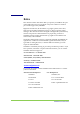
V-Switch Overview The V-Switch provides protocol bridging, routing, switching and volume management in a single platform. Figure 1, page 17, details a standard V-Switch network topology. Two VSwitches sit in the center of the network, providing load balancing and failover ability. Above the V-Switches are IP clouds connecting the network(s) management and host stations. The hosts can connect to the V-Switch directly or via an IP cloud.
Tower Hostbox Tower box Host Tower Hostbox Management Clients Terminal Cloud IP Cloud Management Clients Terminal IP Cloud Cloud Tower box Host V-Switch 1 V-Switch 2 10236 FC Cloud Cloud RAID JBOD SCSI Connection SCSI Connection Figure 1. RAID RAID RAID V-Switch Network Topology Order of Operations Whether being used as a bridging switch between FC or SCSI and iSCSI or as a storage virtualization switch, the V-Switch is operated in the following manner: STEP 1.
Manual Organization This manual is designed to guide you step-by-step through V-Switch installation, configuration, virtualization, maintenance and troubleshooting. The chapters are set up as follows: 18 Table 1: Manual Chapter Organization Chapter Title Description Chapter 2 “Installing the V-Switch 2000,” page 21 Explains the V-Switch2000 chassis, cabling connections and power up procedures.
Chapter Title Description Appendix A “Sample Configurations,” page 251 Provides working examples of common V-Switch configurations. CLI - Command Line Interface The Command Line Interface (CLI) is used to implement all V-Switch management functions, including switching, virtualization and security. The CLI is available via: Console port via an RS232 connection. 10/100 Ethernet Management port via a Telnet session (V-Switch 3000 only). 1 Gb Ethernet port Eth1 via a Telnet session.
Command Description ! RETURN TO MAIN MENU Esc ABORT CURRENT COMMAND # DISPLAY LAST COMMAND TO VIEW COMMAND HISTORY Tab COMPLETE A COMMAND TO THE POINT OF AMBIGUITY Technical Assistance SANRAD is continually striving to provide top-of-the-line products. If you have questions, comments or require technical assistance, you can contact SANRAD Technical Support at: US and Americas: 1-866-301-8155 International: +972-3-941-1890 techsupport@sanrad.
2 Installing the V-Switch 2000 IN THIS CHAPTER The V-Switch 2000 is a 1U high performance storage networking appliance that can be surface or rack mounted. CHASSIS After mounting the V-Switch 2000, connect the requisite cables.
Chassis The V-Switch 2000 is a 1 U surface or rack-mountable storage network appliance. Its front panel includes the console port, network ports, storage ports, system indicator LEDs and reset button. Its back panel includes the fans and power supply. Front Panel RS232 console port 2. Two 1 Gb copper Ethernet network port interfaces 3. Two SCSI or two FC storage port interfaces 4. Reset push button 10203 1. 1 3 4 V-Switch 2000 Front Panel – SCSI 10209 Figure 2. 2 1 Figure 3.
Back Panel Fans 6. Power supply 10214 5. 5 Figure 4. 6 V-Switch 2000 Back Panel System Indicator LEDs Table 4 lists the V-Switch 2000 indicator LEDs as shown in Figure 5, page 24.
1 3 4 2 2 3 5 10204 1 Figure 5. V-Switch 2000 LEDs – SCSI 1 2 2 4 10210 1 Figure 6.
Surface Mounting The V-Switch 2000 chassis is manufactured with four chassis feet. The VSwitch 2000 is ready to be mounted on any secure flat surface. If you plan to rack mount the V-Switch 2000, continue with “Rack Mounting.” Rack Mounting The V-Switch 2000 chassis can be mounted on a 19-inch rack. The V-Switch 2000 can be mounted alone or two V-Switches can be joined and mounted together in a single 1U space. The V-Switch 2000 is shipped with an accessory packet of hardware.
STEP 4. ATTACH THE REAR L-BRACKET If a single V-Switch is being mounted, attach the rear L-bracket to the left side of the V-Switch. If dual V-Switches are being mounted, attach a second rear L-bracket to the right side of the right V-Switch as well. STEP 5. ATTACH THE V-SWITCH 2000 TO THE RACK MOUNTING POSTS Insert the rear of the V-Switch 2000 between the rack mounting posts until the L-bracket(s) touch the rack mounting posts.
Storage Port Connections Connect the SAN storage devices or fabric to the V-Switch 2000 using the FC/SCSI storage ports. The storage ports are located on the front right of the V-Switch 2000. The type of storage ports on your V-Switch 2000 will vary depending on your VSwitch 2000 order specifications – either two SCSI or two FC ports. The V-Switch 2000 contains a storage auto-discovery function.
10211 FC Storage Ports Figure 8. Table 6: V-Switch 2000 FC Storage Ports FC Storage Port Connection Types FIBRE CHANNEL 1 GBIT/2 GBIT NL_PORT OR N_PORT OF EITHER Your exact port configuration will depend on your VSwitch 2000 order specifications.
Network Port Connections The copper network ports, labeled Eth 1 and 2, are located on the front left of the V-Switch 2000. Use the 1Gb Ethernet ports to connect to the network or directly to the host station. When configuring your network topology, keep in mind that the current initiator technology does not support volume access by more than one server at a time.
Console Port Connection 10207 The console port, labeled Console, is located on the front left of the VSwitch 2000. Use this RS232 port and included male-female straight cable to connect a console or dumb terminal to the V-Switch 2000 for initial system configuration and local management. Console Port Figure 10. V-Switch 2000 Console Port Powering Up Do not power the VSwitch 2000 up and down quickly.
10213 Power Switch Figure 11. V-Switch 2000 Power Supplies Reconfirm that all storage devices are powered up. Plug the power cable into the V-Switch 2000 power supply and then into the power source. Push the power switch to the ON position. The V-Switch 2000 powers up. The Power indicator LED on the front right of the V-Switch 2000 turns green. Each network port 1 Gb indicator LED turns green only if connected to the network and operating at 1 Gb.
User Notes 32 SANRAD V-Switch User Manual
3 Installing the V-Switch 3000 IN THIS CHAPTER The V-Switch 3000 is a 1U high performance storage networking appliance that can be surface or rack mounted. CHASSIS After mounting the V-Switch 3000, connect the requisite cables.
Chassis The V-Switch 3000 is a 1 U surface or rack-mountable storage network appliance. Its front panel includes the LCD display and programming buttons, system indicator LEDs and network ports. Its back panel includes the storage ports, redundant power supplies, compact flash and console port. Front Panel 1. LCD display 2. LCD display programming buttons 3. One 10/100 Management Port 4. Three 1 Gb Ethernet Network Ports; both copper and FO interfaces 5.
System Indicator LEDs Table 8 lists the V-Switch 3000 indicator LEDs as shown in Figure 14.
Surface Mounting The V-Switch 3000 chassis is manufactured with four chassis feet. The VSwitch 3000 is ready to be mounted on any secure flat surface. If you plan to rack mount the V-Switch 3000, continue with “Rack Mounting.” Rack Mounting The V-Switch 3000 chassis can be mounted on a 19-inch rack. The V-Switch 3000 is shipped with an accessory packet of hardware. This packet includes two L-brackets, two rear mounts (one left and one right) and ten bracket screws for mounting the L-brackets.
Slide the V-Switch 3000 into the rack making sure to position the V-Switch 3000 to rest on the rear mounts. The rear mounts may turn inward slightly before the V-witch 3000 is inserted. If the V-Switch does not enter easily, push the mount lips outward slightly while inserting the V-Switch 3000. Insert the rear of the V-Switch 3000 until the L-brackets touch the rack mounting posts. STEP 5.
receiving the same default storage number on both V-Switches during their auto-discovery cycles. This, in turn, makes cluster configuration easier. The V-Switch 3000 supports up to four storage ports in any combinations in pairs of the following: Table 9: Storage Port Connection Types FC CONNECTOR Your exact port configuration will depend on your VSwitch 3000 order specifications.
Network Port Connections The network ports, labeled Eth 1, 2 & 3, are located on the front right of the V-Switch 3000. Use the 1Gb Ethernet ports to connect to the network or directly to the host station. Each network port has both a fiber optic and copper connector but only one cable, either fiber optic or copper, can be connected to each port.
CABLE LENGTH SFP 1000BASE-TX (TWISTED-PAIR) OVER CATEGORY 5 UTP UP TO 100M __ 10218 Ethernet (Network) Ports Copper RJ45 Figure 17. Fiber Optic SFP V-Switch 3000 Network Ports Each network port has two LEDs: act – indicates whether the port is connected and active: slow blink – active; fast blink – port traffic. 1 Gb – indicates whether the port is operating at 1 Gb. The LED is off if the port is operating at 10/100.
Management Port Connection The management port, labeled 10/100 mgmt, is located on the front center of the V-Switch 3000. Use this 10/100 port to connect a host station either directly or via a network to the V-Switch 3000. When connecting directly to the V-Switch 3000 via 10/100, use a male-female straight cable. When connecting via a network, use a standard network cable. For more information on V-Switch 3000 management options, please refer to “Introduction to Managing the V-Switch,” page 46.
LCD 10221 The LCD is located on the front left of the V-Switch 3000. The LCD has two rows of 16 characters each in addition to six control buttons. Use the LCD buttons and display for initial V-Switch 3000 configurations immediately after power up. For more information on configuring the V-Switch 3000 via LCD, please refer to “Configuring the V-Switch 3000 Management Parameters via LCD,” page 48. LCD Figure 21.
Scalability Port 10241 The scalability port is for future use and is not supported currently. The scalability port, labeled Scalability, is located on the back lower left side of the V-Switch 3000. The scalability port is a V-Switch 3000 interconnectivity port. Using SANRAD’s proprietary scalability cable, two V-Switches can be connected and synchronized to function as one V-Switch 3000 to provide resource sharing and computational power increase. Scalability Port Figure 22.
Powering Up You can power up the V-Switch 3000 once you have connected and powered up the storage devices. The V-Switch 3000 contains a storage auto-discovery function. At power- up the V-Switch 3000 automatically scans for and registers all attached and powered up network storage devices. Therefore, power up all storage devices before powering up the VSwitch 3000. Storage devices added after V-Switch 3000 power- up will be registered in the next V-Switch 3000 storage network scan.
4 V-Switch Configuration IN THIS CHAPTER INTRODUCTION TO MANAGING THE VSWITCH CONFIGURING THE VSWITCH 3000 MANAGEMENT PARAMETERS VIA LCD CONFIGURING THE MANAGEMENT CONSOLE INITIALIZING THE VSWITCH After the V-Switch is connected properly to the physical disks, management station and the network and powered up, the VSwitch must be configured.
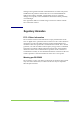
Introduction to Managing the V-Switch After powering up the V-Switch you must configure its management parameters before doing any other configuration operations, namely creating virtual disks. This basic configuration can be done using the V-Switch LCD panel or via a console or dumb terminal to open a direct connection with the V-Switch’s RS232 console port. The V-Switch can be managed in one of three different ways with each requiring a different management configuration.
B In-Band Management Telnet Station IPCloud Cloud Gb port Gb port 10/100 port RS232 port Modem 10/100 port RS232 port Fast Ethernet Network C A C Clients Console Clients Console 10223 Modem Clients Terminal Management Out-of-Band Management Figure 25.
Configuring the V-Switch 3000 Management Parameters via LCD After successfully powering up, the V-Switch 3000 LCD display panel displays: V-Switch 3000 Status: OK 10244 Using the Enter and arrow buttons, you toggle between LCD screens and input the V-Switch management parameters. The Back and Forward buttons toggle between spaces. The Up and Down buttons scroll between values in a space. Press Esc at any time to escape from a field or return to the previous screen level. Figure 26. STEP 1.
Enter the management port IP mask using the arrow buttons. Mask _ _ _._ _ _._ _ _._ _ _ 2 5 5.2 5 5.2 5 5.0 0 0 Press Enter to enter the IP mask and return to the main V-Switch Status screen. V-Switch 3000 Status: OK After initializing the V-Switch via the LCD display panel and buttons, you are ready to connect your management station to the V-Switch via the Eth1 management port and appropriate cable. You are now ready to log in to the V-Switch. Continue with “Initializing the V-Switch,” page 50.
After configuring the console, you can now log in to the V-Switch using your installed terminal emulation application and configure the basic VSwitch parameters. You will then be able to manage the V-Switch via the 1 Gb Ethernet port, Eth1 (in-band) or the 10/100Mb management port (outof-band). Continue with “Initializing the V-Switch”. Initializing the V-Switch Before you can begin managing your storage pool, you must initialize the V-Switch.
Enter the default user name, sanrad, and password, sanrad, and press Enter on your keyboard. The CLI prompt > appears. You are now logged in and ready to begin configuring your V-Switch for volume virtualization and exposure. STEP 3. INITIALIZE THE V-SWITCH Use the CLI command init to configure the V-Switch management parameters.
Changing Management Parameters After logging in to the V-Switch, you can change the general management parameters and Telnet communications port as well as add user login profiles. Changing General Management Parameters You can change V-Switch management parameters (IP address and mask) or UDP port number as well as include details of whom to contact in the event of technical difficulties and which read/write communities to send traps to.
SWITCH PARAMETER DEFINITION STATUS EXAMPLE -loc LOCATION LOCATION OF THE CONTACT PERSON OPTIONAL ext4838 -rld REPORT MODE FOR OPTIONAL no DISCOVERING DEVICE LUNS YES OR NO LUN DISCOVERY DEFAULT: YES -telnet TELNET PORT PORT FOR SWITCH V- COMMUNICATIONS -rcom -wcom READ COMMUNITY TO COMMUNITY GET INFORMATION WRITE COMMUNITY COMMUNITY TO SET INFORMATION 1597 OPTIONAL DEFAULT: 23 OPTIONAL DEFAULT: PUBLIC OPTIONAL DEFAULT: PRIVATE Example: The V-Switch alias is reset to V-Sw
Parameter Value Object ID Time Since Last Reset Mgmt IP Address Mgmt UDP Port Date & Time [DD/MM/YY] Telnet Port Eth FC Read Community Write Community 1.3.6.1.4.1 10059 1.1.2 12 days 17 hours 29 min 32 sec 212.199.43.47 161 21/04/02 13:33 23 Up Up Public Private Changing the Telnet Communications Port If your Telnet communications connection to the V-Switch traverses a firewall, the standard Telnet communications port 23 may be blocked by the firewall as a security measure.
SWITCH PARAMETER DEFINITION STATUS EXAMPLE -rcom READ COMMUNITY COMMUNITY TO GET INFORMATION OPTIONAL public COMMUNITY TO SET INFORMATION OPTIONAL TO SEND TRAPS TO MANAGER OPTIONAL YES: SEND NO: DO NOT SEND -wcom -trap WRITE COMMUNITY TRAP DEFAULT: PUBLIC private DEFAULT: PRIVATE yes DEFAULT: YES Example An SNMP manager is added on IP address 212.199.43.96. It receives traps through port 162.
For information on changing or removing user profiles, please see “User Profiles,” page 178.
Configuring the Storage Ports If your V-Switch configuration contains SCSI devices, you can set the storage port bus ID. If your V-Switch configuration contains FC storage ports, you can change the default configuration of each port. Use the CLI command interface show to show all storage port connections.
SWITCH PARAMETER DEFINITION STATUS EXAMPLE -if INTERFACE STORAGE PORT NUMBER MANDATORY pscsi3 -id IDENTITY SCSI BUS OPTIONAL 12 IDENTITY DEFAULT: 7 Example Storage port 3, pscsi3, is assigned SCSI bus ID 12. pscsi set busid –if pscsi3 –id 12 Viewing the FC Port Information Use the CLI command fc interface show to view all FC ports on the VSwitch; their World Wide Port Names (WWPN) and administrative and operative types.
SWITCH PARAMETER DEFINITION -cm CONNECTION MODE STATUS EXAMPLE OPTIONAL FAB: FABRIC PRL: PRIVATE LOOP PUL: PUBLIC LOOP private Example fc set –if fc2 –sp 1 –pt nl –cm prl Viewing the V-Switch World Wide Node Name Use the CLI command fc node show to view the V-Switch World Wide Node Name (WWNN). fc node show Name Description WWNN Function Chapter 4: V-Switch Configuration V-Switch1 SW Version 1.
Configuring the Network Ports Each network port must be located on a separate subnet. Each network port can have more than one IP address. To connect the V-Switch to the network you need to assign IP parameters to each 1Gb Ethernet network port connected to a network. Each network port must be located on a separate subnet. Each network port can have more than one IP address. Use the CLI command ip config set to assign IP parameters.
10224 212.199.43.56 Figure 28. Ethernet Port 1 IP Address Checking the IP Configurations After setting the management and network port IP addresses, you can use the CLI command ip config show to access the IP Configuration Table and view all assigned port IP addresses. ip config show Table 13: V-Switch IP Configuration Table IP Address Net Mask Activity mgmt eth1 eth1 eth2 eth3 eth3 212.199.43.46 212.199.43.56 212.199.43.57 212.199.75.66 212.199.12.67 212.199.12.70 255.255.255.0 255.255.255.0 255.
ip config remove You need to define one parameter to remove a network port IP address: SWITCH PARAMETER DEFINITION STATUS EXAMPLE -ip IP ADDRESS IP ADDRESS TO MANDATORY 212.199.12.70 REMOVE FROM THE NETWORK INTERFACE PORT Example: The IP address 212.199.12.70 is removed from Eth3 leaving the port with only one IP address, 212.199.12.67. 10226 ip config remove –ip 212.199.12.70 212.199.43.46 212.199.75.66 212.199.43.56 212.199.12.67 212.199.43.57 Figure 30.
Discovering iSCSI Targets iSCSI target discovery is performed across the IP-SAN by the iSCSI initiator located on the server. The V-Switch supports three methods for reporting iSCSI targets in the IP-SAN to iSCSI initiators: iSCSI Discovery Session SLP iSNS iSCSI Discovery Session The V-Switch supports iSCSI discovery sessions for reporting iSCSI targets to iSCSI initiators.
ip isns show Table 14: iSNS Servers 212.199.56.45 Deleting an iSNS Server Use the CLI command ip isns remove to remove an iSNS server from the VSwitch iSNS client. ip isns remove You need to define one parameter to remove an iSNS server address: SWITCH PARAMETER DEFINITION STATUS EXAMPLE -ip IP ADDRESS IP ADDRESS OF ISNS SERVER MANDATORY 212.199.43.1 Configuring iSCSI Portals Do not create an iSCSI portal on the management IP address. The V-Switch supports a maximum of 100 portals.
iscsi portal create –ip 212.199.43.66 Viewing iSCSI Portals You can view all created portals using the CLI command iscsi portal show. iscsi portal show Table 15: iSCSI Portals Protocol Address Type Address Port 6 ipv 4 212.199.43.56 3260 6 ipv 4 212.199.43.57 3260 6 ipv 4 212.199.43.66 5003 6 ipv 4 212.199.43.67 5003 Protocol 6 is the transport protocol for iSCSI. Address type IPv 4 designates a four byte IP address.
Configuring IP Routing To enable communications between the V-Switch and IP networks located outside the V-Switch LAN, you must configure IP routing paths for each external network port. The IP route begins with a specified network port on the V-Switch and ends at the external network IP address. Just as each IP address is unique, each IP routing path is unique. There can be only one IP route to a given external network IP address per V-Switch.
Adding an IP Route You can enable communications to networks outside of your LAN by configuring an IP routing path. This allows volume access to hosts located on external networks. Use the CLI command ip route add to add an IP routing path to your V-Switch. If you are working in a V-Switch cluster, you must configure the IP route on both V-Switches in the V-Switch cluster. For more information on V-Switch clusters, see “Introduction to V-Switch Clusters,” page 72.
ip route default –gw 20.20.10.20 Checking IP Routes After creating an IP routing path, you can ping any IP-connected device from the V-Switch Eht1 to check that the routing is configured correctly. Use the CLI command ping to ping an IP address from the V-Switch. Make sure that the route is defined on the other side as well. ping You need one parameter to check an IP routing path from the V-Switch. SWITCH PARAMETER DEFINITION STATUS EXAMPLE -ip IP ADDRESS IP ADDRESS TO MANDATORY 172.17.200.
ip route remove You need three parameters to remove an IP routing path. SWITCH PARAMETER -dip DESTINATION IP DEFINITION STATUS EXAMPLE IP OF HOST MANDATORY 10.12.40.0 MANDATORY 255.255.255.0 MANDATORY eth3 STATION -dmask -if DESTINATION MASK IP MASK OF HOST INTERFACE ALIAS NETWORK PORT TO OPEN COMMUNICATION THROUGH STATION Example: The routing path to destination network IP 10.12.40.0 (IP mask 255.255.255.0) is removed from network port Eth3. ip route remove –dip 10.12.40.0 –dmask 255.
User Notes 70 SANRAD V-Switch User Manual
5 V-Switch Cluster Configuration IN THIS CHAPTER INTRODUCTION TO VSWITCH CLUSTERS CONFIGURING A VSWITCH CLUSTER MANAGING A CLUSTER You can configure a V-Switch cluster using two V-Switches of the same type. A cluster is a group of storage units and switches that function as one unit for virtualization and provide high availability in the event of V-Switch failover. A cluster can be configured between two V-Switches using CLI or SANRAD’s StoragePro management GUI.
Introduction to V-Switch Clusters Two V-Switches can be concurrently connected to the same FC storage devices to balance volume exposure thus creating a V-Switch cluster. In a cluster, each V-Switch interacts in an active-active, peer-to-peer fashion with the other V-Switch, or neighbor, in the cluster. No one V-Switch must be configured specially to act as the master V-Switch in the cluster providing higher flexibility in building a cluster.
. Vol 1 IP1,Target 1 iSCSI initiator Vol 2 iSCSI initiator Tower Hostbox 1 Tower Hostbox 2 IP2,Target 2 IPCloud SAN IP1-active IP2-inactive V Switch 1 V Switch 2 iSCSI Target 1 wwui1 iSCSI Target 2 wwui2 Vol 1 Vol 2 LU0 LU0 JBOD Figure 32. When working in a cluster, the V-Switch can support a maximum of 100 portals: 50 active and 50 inactive.
In Figure 33, V-Switch 1 has gone off-line. V-Switch 2 activates V-Switch 1’s IP address and takes over exposure of Volume 1 to Host 1, represented by the orange dashed line. Host 1 continues to access Volume 1 through the same IP address as it did before its V-Switch went off-line. Host 1 has no way of knowing that its regular V-Switch is off-line. Host 1’s storage performance is not impacted by the off-line V-Switch.
Configuring a V-Switch Cluster Setting the V-Switch ID When you configure a cluster, you must give each V-Switch a different device ID for proper cluster functioning. Use the CLI command device set to configure the V-Switch ID for each V-Switch. device set SWITCH PARAMETER DEFINITION STATUS EXAMPLE -id V-SWITCH ID ID OF V-SWITCH MANDATORY IN A CLUSTER 1 IN A CLUSTER EACH V-SWITCH MUST HAVE A DIFFERENT ID 0 OR 1 Example: There are two V-Switches in a cluster. In V-Switch 1 the ID is set to 1.
neighbor add You need to define two parameters to notify a V-Switch of a neighbor. SWITCH PARAMETER DEFINITION STATUS EXAMPLE -nb NEIGHBOR ALIAS OF NEIGHBOR MANDATORY VSwitch2 MANDATORY 212.199.43.75 TO ADD TO CLUSTER -ip IP ADDRESS IP ADDRESS OF MGMT PORT ON NEIGHBOR Example: A V-Switch is informed that it has a neighbor, VSwitch2, and that it can establish communication with VSwitch2 via IP address 212.199.43.75. neighbor add –nb VSwitch2 –ip 212.199.43.
All V-Switch database configurations must be replicated in both V-Switches when creating a V-Switch cluster, including IP addresses, portals, IP routes, volumes and targets. Vol 1 iSCSI initiator Tower Hostbox 1 IP1,Target 1 Vol 2 iSCSI initiator Tower Hostbox 2 IP: 212.199.43.90 IP2,Target 2 IP: 212.199.43.75 IPCloud SAN IP1-active: 212.199.43.90 IP2-inactive: 212.199.43.75 IP2-active: 212.199.43.75 IP1-inactive: 212.199.43.
Working with SCSI Storage Devices The V-Switch default SCSI bus ID is 7. If your storage cluster includes SCSI storage devices, one of the V-Switch’s default SCSI bus ID must be changed. They cannot both be 7 on the same SCSI bus. Use the CLI command pscsi set busid to change the SCSI bus ID on one of the V-Switches.
Example: Every 2 seconds V-Switch 1 sends out a keep alive signal. If, after 6 seconds from the last keep alive signal, V-Switch 1 does not receive another keep alive signal from its neighbor, it enters a suspicious interval. If, after 10 seconds from the last keep alive signal, V-Switch 1 enters a dead interval and begins activating the failover process. Enabling and Disabling Failover Once you have configured your cluster parameters, you need to enable the failover functionality.
Viewing V-Switch Neighbor Details Use the CLI command neighbor show to view the neighbor configured on a V-Switch. neighbor show Table 16: Neighbors in a Cluster Name IP Address UDP VSwitch2 212.199.43.75 161 SNMP Timeout (msec) SNMP # of Retries Use the CLI command neighbor details to list the details of a neighbor in a cluster. neighbor details You need to define one parameter to list neighbor details.
Managing a Cluster If you modify a V-Switch alias or management IP address, you must implement the updates in the neighboring V-Switch. Use the CLI command neighbor set to update a V-Switch on changes in its neighbor. neighbor set You need to define the parameter(s) to modify to reset a neighbor alias or IP address in a cluster.
Use the CLI command cluster set to modify the default keep alive intervals. cluster set You need to define the parameters you want to modify in the keep alive interval.
6 Volume Configuration IN THIS CHAPTER After you have configured the V-Switch general parameters, you can begin defining the storage topology using the Volume Manager. INTRODUCTION TO VOLUME CONFIGURATION Using the Volume Manager, you can create subdisks on physical disk storage devices or leave the physical disk as is.
Introduction to Volume Configuration This chapter describes how to identify the SAN storage devices and use them to create subdisks and virtual volumes. Each description includes: A general description and generic diagram. The basic command, switches and parameters needed to execute the command. An example of how to use the command with an accompanying diagram. The specific examples used in this chapter contain two JBODs; each JBOD having four disks, each with a volume of 18 GB.
Identifying Available Storage Devices The V-Switch supports a maximum of 512 disks. Before beginning to configure virtual volumes, you need to know which storage devices are available. Use the CLI command storage show to show the available storage devices and their corresponding aliases needed to configure volumes storage show Table 18: Storage Devices Alias Entity Name Stor_1 Stor_2 Stor_3 Stor_4 500507606058c900 2000002037f88fb8 2000002037c32b1f 2000002037c32450 LUN Oper.
storage blink activate –s Stor_1 –t 120 Use the CLI command storage blink abort to stop the blinking before the end of the set time. storage blink abort You need to define one parameter to stop blinking a storage device: SWITCH PARAMETER DEFINITION STATUS EXAMPLE -s STORAGE DEVICE ALAIS OF DEVICE TO BLINK MANDATORY Stor_1 Once a storage device has been identified, use the CLI command storage set to change the device alias or include helpful information on the device.
The V-Switch also recognizes all write-protected storage devices. Use the CLI command storage details to view a device’s details, including if it is write-protected. storage details You need to define one parameter to view a disk’s details: SWITCH PARAMETER DEFINITION STATUS EXAMPLE -s STORAGE ALIAS OF STORAGE TO VIEW MANDATORY Disk2JBOD5 Table 19: Storage Details Alias: Entity Name: LUN(Logical Unit Number) Vendor Name: Additional Info: Transport type: Oper.
Creating a Transparent Volume Transparent volumes cannot be used in further volume hierarchies. You can take a physical disk and its existing configured storage data and convert it to a directly accessible, or transparent, virtual volume using the CLI command volume create transparent. A transparent volume is ready for direct host exposure. Please refer to “Volume Exposure & Security,” page 107. Tape devices must be virtualized as transparent volumes.
Trasparent Volume 1 10101 Disk 1, LUN0 RAID Controller Figure 36. Transparent Volume 1 After creating the transparent volume, you can use the CLI command volume show to verify the volume creation.
Creating a Subdisk (LUN Carving) You can create one or more subdisks on a physical disk. The subdisks can then be converted to simple volumes to be used for creating concatenated, striped and mirrored virtual volumes. When you create a subdisk, only the defined area is converted into a subdisk. You must individually convert each disk area into a subdisk for the physical volume to be usable by the Volume Manager. Disk Figure 37.
JBOD 1 JBOD 2 Disk 2 Disk 5 Disk 6 Disk 3 Disk 4 Disk 7 Disk 8 10066 Disk 1 Figure 38. If you are working in a V-Switch cluster, this volume must be configured on both V-Switches. Disk 1 before Subdisk In Figure Error! Bookmark not defined., page Error! Bookmark not defined., Subdisk 1 has been created on Disk 1. The subdisk is 18,000,000 blocks long (9 GB). The Volume Manager begins counting the 18,000,000 blocks from block 0.
You need to define one parameter to view subdisks. SWITCH PARAMETER DEFINITION STATUS EXAMPLE -d DISK ALIAS ALIAS OF DISK TO SHOW SUBDISKS FROM OPTIONAL USE THIS SWITCH TO LIST Disk1 ONLY THE DETAILS OF A SPECIFIC DISK This command calls up the following table. Table 21: Details of all Subdisks Disk Subdisk Start Address Length Vol Disk1 Subdisk1 0 512 no For the rest of the physical volume on Disk 1 to be usable to the Volume Manager, you must create another subdisk.
Creating a Simple Volume The V-Switch supports a maximum of 512 volumes. Before you can build concatenated, mirrored and striped volumes, you must create simple volumes from each disk or subdisk in your storage network. A physical disk or subdisk is converted directly to a virtual simple volume. A simple volume differs from a transparent volume in that virtual volume hierarchies can be built on top of simple volumes but not on transparent volumes.
If you are working in a V-Switch cluster, this volume must be configured on both V-Switches. Assigning a volume alias is optional. If you do not include a volume alias in the command, the volume alias will default to the subdisk alias in which the volume is located. For example, a simple volume created on Subdisk 6 will be named Subdisk 6 by default. Use the –sd switch to assign a subdisk or the –d switch to assign a disk.
Creating a Concatenated Volume The V-Switch supports a maximum of 512 volumes. To accommodate large volumes of data or to best utilize small volumes spread over several disks, you can concatenate physical volumes across storage devices to create a larger virtual volume. In Figure 43, the volume is divided into two equitable chunks to be mapped across two disks. Data blocks 1 – 4 are mapped to Disk 1, blocks 13 – 16. Data blocks 5 – 8 are mapped to Disk 2, blocks 13 – 16.
The system default for the number of children being concatenated is two. Therefore, you only need to specify the number of children for numbers greater than two. Example: If you are working in a V-Switch cluster, this volume must be configured on both V-Switches. In Figure 44, Simple Volume 5 and Simple Volume 12, both built over an entire physical disk, are concatenated to create a concatenated volume, Concat 1. Data is read/written first to Simple 5.
Creating a Striped Volume The V-Switch supports a maximum of 512 volumes. A striped volume has data written equitably across two or more disks to provide higher read/write rates. Subdisks within a striped volume need to be on different disks to realize the benefits of striping. Throughput increases with the number of disks within a striped volume. In Figure 45, data block 1 is mapped to section 1 of Disk 1; data block 2 is mapped to block 1 of Disk 2.
SWITCH PARAMETER DEFINITION STATUS EXAMPLE –ch CHILD FIRST VOLUME (CHILD) TO WRITE MANDATORY Simple2 MANDATORY Simple4 MANDATORY Simple8 MANDATORY Simple10 TO –ch CHILD SECOND VOLUME (CHILD) TO WRITE TO –ch CHILD THIRD VOLUME (CHILD) TO WRITE TO –ch CHILD FOURTH VOLUME (CHILD) TO WRITE TO The system default for the number of children data is being striped across is two. Therefore, you only need to specify the number of children for numbers greater than two.
Striped Volume 1 JBOD 1 JBOD 2 Disk 2 Disk 5 Disk 6 Simple 1 Simple 3 Simple 7 Simple 9 Simple 2 Simple 4 Simple 8 Simple 10 Disk 3 Disk 4 Disk 7 Disk 8 Simple 5 Simple 6 Simple 11 Simple 12 10060 Disk 1 Figure 46.
Creating a Mirrored Volume Use mirroring to create data backups. The V-Switch supports a maximum of 512 volumes. A mirrored volume is synchronously written into two or more volumes. Mirrored volumes provide protection against data loss from a physical disk crash. To be a true mirror and realize the full potential of a mirror, the mirrored volumes must be located on different physical disks. In Figure 47, data block 1 is mapped to both block 5 on Disk 1 and block 9 on Disk 2.
Example: If you are working in a V-Switch cluster, this volume must be configured on both V-Switches. In Figure 48, a mirrored volume, Mirrored 1, is created using two children, Simple 6 and Simple 11. volume create mirror –vol Mirrored1 –ch Simple6 –ch Simple11 Mirrored Volume 1 JBOD 1 JBOD 2 Disk 2 Disk 5 Disk 6 Simple 1 Simple 3 Simple 7 Simple 9 Simple 2 Simple 4 Simple 8 Simple 10 Disk 3 Disk 4 Disk 7 Disk 8 Simple 5 Simple 6 Simple 11 Simple 12 10059 Disk 1 Figure 48.
See the working example of off-line data replication “Replicating Data Offline,” page 264. volume mirror sync You need to define two parameters to synchronize a volume: SWITCH PARAMETER DEFINITION STATUS EXAMPLE -src SOURCE VOLUME ORIGINAL VOLUME TO SYNCHRONIZE MANDATORY Simple3 MANDATORY Simple5 TO -dst DESTINATION NEW VOLUME TO VOLUME ADD TO SYNCHRONINZE Example: The online volume Simple3 is synchronized to the online volume Simple5.
Creating a RAID 10 and RAID 0+1 You will need two separate commands to create a RAID 10 or 0+1 volume. RAID 10 first creates mirrored volumes and then creates a striped volume of the mirrored volumes. This gives the advantage of both high performance and data redundancy. In Figure 49, page 104, in the first mirrored volume, data block 1 is mapped to both block 1 on Disk 1 and block 1 on Disk 2. Data blocks 3, 5 and 7 are mapped to blocks 2, 3 and 4 on both Disks 1 and 2.
Example: If you are working in a V-Switch cluster, this volume must be configured on both V-Switches. In Figure 51, page 105, to begin creating a RAID 10 volume, a mirrored volume, Mirror 2, is created using two children: Simple 1 and Simple 7.
Mirrored Volume 2 Mirrored Volume 3 JBOD 1 JBOD 2 Disk 2 Disk 5 Disk 6 Simple 1 Simple 3 Simple 7 Simple 9 Simple 2 Simple 4 Simple 8 Simple 10 Disk 3 Disk 4 Disk 7 Disk 8 Simple 5 Simple 6 Simple 11 Simple 12 Figure 51. Second Mirrored Volume of RAID 10 10062 Disk 1 If you are working in a V-Switch cluster, this volume must be configured on both V-Switches.
Striped Volume 2 Mirrored Volume 2 Mirrored Volume 3 JBOD 1 JBOD 2 Disk 2 Disk 5 Disk 6 Simple 1 Simple 3 Simple 7 Simple 9 Simple 2 Simple 4 Simple 8 Simple 10 Disk 3 Disk 4 Disk 7 Disk 8 Simple 5 Simple 6 Simple 11 Simple 12 10063 Disk 1 Figure 52. Striped Volume of RAID 10 To create a RAID 0+1 volume, invert the commands and first create a striped volume and then mirrored volumes of the stripe.
7 Volume Exposure & Security IN THIS CHAPTER INTRODUCTION TO VOLUME EXPOSURE & SECURITY CREATING AN ISCSI TARGET CHANGING THE DEFAULT IDENTITY CREATING AN IDENTITY ADDING INITIATORS TO AN IDENTITY After you have created your virtual volumes and storage hierarchies, you want to expose them securely to hosts using the iSCSI protocol. Up to this point, all volumes created are invisible and inaccessible to network hosts.
Introduction to Volume Exposure & Security iSCSI Targets Data is able to be transferred via iSCSI when an iSCSI initiator establishes a TCP connection with an iSCSI target. The iSCSI initiator resides in the host computer and is configured by the system administrator. The iSCSI target resides in the V-Switch and is created by the volume manager.
V-Switch iSCSI Target 2 wwui2 iSCSI Target 3 wwui3 Vol 1 Vol 2 Vol 3 Vol 4 LU0 LU0 LU0 LU1 10124n iSCSI Target 1 wwui1 Figure 53. iSCSI Target Access Once a volume has a LUN and is attached to a target, it is accessible to iSCSI initiators. Each initiator can access, read and write into the volume. Identities To allow selective iSCSI initiator access to iSCSI target volumes, the VSwitch uses identities to define pools of initiators. An identity is a userdefined list of iSCSI initiators.
wwui1 wwui2 wwui3 An iSCSI initiator can be listed in multiple identities. Ident A wwui4 wwui5 Ident B wwui6 wwui7 wwui8 10149 wwui9 wwui10 Figure 55. Identity B’s iSCSI Initiators In Figure 55, there are six iSCSI initiators in Identity B: WWUI 3, 4, 6, 7, 8 and 9. Note that iSCSI initiator 8 is in both Identity A and B. An iSCSI initiator can be listed in multiple identities. wwui1 wwui2 wwui3 Ident A wwui4 wwui5 Ident B wwui6 wwui7 wwui8 Ident C 10150 wwui9 wwui10 Figure 56.
wwui1 iSCSI Target 1 wwui21 wwui2 An identity can be used with more than one target. Vol 1 Ident A wwui3 wwui4 iSCSI Target 2 wwui22 Vol 2 Vol 3 wwui5 Ident B wwui6 Vol 4 iSCSI Target 3 wwui23 wwui8 Ident C iSCSI Target 4 wwui24 wwui9 Vol 5 Vol 6 wwui10 Figure 57. 10151 wwui7 Identities Coupled with Targets In Figure 57, Identity A is coupled with both Targets 1 and 2. Identity B is coupled with Target 3. Identity C is coupled with Target 4.
wwui1 wwui2 wwui3 Ident A wwui4 rit d-W Rea e Re ad -O nly iSCSI Target 1 wwui21 iSCSI Target 2 wwui22 Vol 1 Vol 2 Vol 3 wwui5 Re ad -W rite wwui7 wwui8 Ident C Rea d-W wwui9 rite iSCSI Target 3 wwui23 iSCSI Target 4 wwui24 Vol 4 Vol 5 Vol 6 10152 Ident B wwui6 wwui10 Figure 58. Access Rights per Identity-Target Pair In Figure 58, Identity A is coupled with both Target 1 and Target 2. The Identity A – Target 1 pair is assigned iSCSI initiator read-write access to Target 1 volumes.
read-only, depending on the positioning of the identities. If Identity A is assigned position 1 and Identity B is assigned position 2, Identity B is scanned first by the V-Switch. A match is made and the scan is stopped. No further identities will be scanned. Therefore, iSCSI initiator WWUI8 will be granted read-write access. If the positions are reversed and Identity B is assigned position 1 and Identity A is assigned position 2, iSCSI initiator WWUI8 will be granted read-only access.
initiators. The default identity is assigned position 0, meaning it is the last scanned. Unlike user-created identities, the default identity cannot be uncoupled from a target. Its access can only be modified.
If iSCSI initiator WWUI1 tries to login to Target 2, the V-Switch first scans Identity B. It does not find the initiator listed so it continues to scan the next identity, the default identity. The default identity blocks all iSCSI initiators, including WWUI1. The scan stops and the initiator is denied access to Target 2’s underlying volumes, Volume 2 and Volume 3, since the default identity is configured as not assessable.
Example: If you are working in a V-Switch cluster, each target must be configured on both VSwitches. The target finance is created on V-Switch 1. The WWUI of Finance is billing.sanrad, as shown in Figure 62. iscsi target create –ta finance –tn sanrad.billing – device VSwitch1 iSCSI initiator iSCSI initiator Tower box iqn.1991-05.microsoft:steven.sanrad Tower box iqn.1991-05.microsoft:wilbur.sanrad iqn.com.cisco.steven IPCloud SAN V-Switch1 Default all RW 10177n finance sanrad.billing Figure 62.
Table 22: iSCSI Targets Target Alias Target Name # of LUs Exposed On: finance sanrad.billing 0 Not exposed musicbox musicbox.sanrad 1 VSwitch1 Viewing iSCSI Target Details Use the CLI command iscsi target details to view the details of an iSCSI target. iscsi target details SWITCH PARAMETER DEFINITION STATUS EXAMPLE -ta TARGET ALIAS USER-ASSIGNED ALIAS FOR ISCSI TARGET MANDATORY Finance Table 23: Target Alias: nms153 Target Name: eui.
Table 24: 118 Default Identity Target Access Target Position Identity Access finance 0 DEF_ALL read-write musicbox 0 DEF_ALL not accessible musicbox 1 musicdept read-write SANRAD V-Switch User Manual
Changing the Default Identity If you are working in a V-Switch cluster, the default access rights must be disabled on both VSwitches. When a target is created, a default access control identity is automatically assigned to its position 0. The default identity allows all hosts read-write access to the target and its underlying volume(s).
Creating an Identity If you are working in a V-Switch cluster, each identity must be configured on both VSwitches. If you want to limit host, meaning iSCSI initiator, access to targets, you must create an identity that is more discriminate than the default identity. Use the CLI command acl identity create to name and describe an identity. When creating identities, keep in mind that: Each identity can contain one or more iSCSI initiators.
iSCSI initiator iSCSI initiator Tower box iqn.1991-05.microsoft:steven.sanrad Tower box iqn.1991-05.microsoft:wilbur.sanrad iqn.com.cisco.steven IPCloud SAN V-Switch1 accounting Default all NA 10178n finance sanrad.billing Figure 63.
Adding Initiators to an Identity If you are working in a V-Switch cluster, each initiator must be added on both VSwitches. After creating an identity, you can begin adding hosts by their iSCSI initiator WWUIs to the identity. The identity is a group of iSCSI initiators. It is not enough for an authorized host to request access to a target. The host must be requesting access from the correct iSCSI initiator. Use the CLI command acl identity add name to add iSCSI initiators to an identity.
Example The host, steven, is added to the identity accounting according to his iSCSI initiator wwui, iqn.1991-05.microsoft:steven.sanrad. acl identity add name –id accounting –name iqn. 1991-05. microsoft: steven.sanrad iSCSI initiator iSCSI initiator Tower box iqn.1991-05.microsoft:steven.sanrad Tower box iqn.1991-05.microsoft:wilbur.sanrad iqn.com.cisco.steven IPCloud SAN V-Switch1 accounting microsoft:steven Default all NA 10179n finance sanrad.billing Figure 64.
If a host has more than one iSCSI initiator installed, both initiators can be included in the identity. acl identity add name –id accounting –name iqn.com. cisco.steven iSCSI initiator iSCSI initiator Tower box iqn.1991-05.microsoft:steven.sanrad Tower box iqn.1991-05.microsoft:wilbur.sanrad iqn.com.cisco.steven IPCloud SAN V-Switch1 cisco.steven accounting microsoft:steven Default all NA 10180n finance sanrad.billing Figure 65.
Assigning Identity Credentials If you are working in a V-Switch cluster, the identity authentication method(s) must be added on both VSwitches. You can require initiator authentication before allowing access to a target and its underlying volume(s). The V-Switch supports CHAP and SRP authentication methods. Microsoft and Cisco initiators support CHAP. Use the CLI command acl identity add chap/srp to assign a login authentication method(s) to initiators in an identity.
Example The user name, steven, with user password, oneveryhotdude, is assigned CHAP credential verification in the identity accounting. acl identity add chap –id accounting –us steven –pw oneveryhotdude iSCSI initiator iSCSI initiator Tower box iqn.1991-05.microsoft:steven.sanrad Tower box iqn.1991-05.microsoft:wilbur.sanrad iqn.com.cisco.steven IPCloud SAN V-Switch1 steven oneveryhotdude cisco.steven accounting microsoft:steven Default all NA 10181n finance sanrad.billing Figure 66.
If a host has more than one iSCSI initiator installed, both initiators can be included in the identity and given authentication methods. The user name and password do not need to be the same for different initiators on the same host. acl identity add chap –id accounting –us steven –pw ilovecookies iSCSI initiator iSCSI initiator Tower box iqn.1991-05.microsoft:steven.sanrad Tower box iqn.1991-05.microsoft:wilbur.sanrad iqn.com.cisco.
After assigning iSCSI initiators and assigning credentials to an identity, use the CLI command acl identity details to view the list of iSCSI initiators. acl identity details You need to define one parameter to view an identity’s details: SWITCH PARAMETER DEFINITION -id IDENTITY NAME OF ACL STATUS EXAMPLE MANDATORY accounting acl identity details –id accounting Table 25: Identity Details Description: Initiators: Accounts allowed read-write access to accounting records iqn.1991-05.
iSCSI initiator iSCSI initiator Tower box iqn.1991-05.microsoft:steven.sanrad iqn.com.cisco.steven Tower box iqn.1991-05.microsoft:wilbur.sanrad CHAP Authentication steven oneveryhotdude IPCloud SAN Tower box RADIUS Server Yes V-Switch1 RADIUS Authentication? No steven ilovecookies cisco.steven accounting microsoft:steven Default all NA 10261 finance sanrad.billing Figure 68.
Example: In Figure 69, the V-Switch is configured to relay CHAP challenges to the identity, accounting, from the user, steven, to the RADIUS server. The VSwitch is configured to communicate with the RADIUS server through port 1812 to IP address 212.199.43.2. The V-Switch – RADIUS key is DataTurnsMeOn. The user password is not configured on the V-Switch. The RADIUS server authenticates the user password and sends the results back to the V-Switch.
Viewing Configured RADIUS Servers Use the CLI command ip radius show to view all configured RADIUS server IP addresses. ip radius show Table 26: Configured RADIUS IP Addresses Address Port 212.199.43.2 1812 212.199.56.
Connecting an Identity and Target If you are working in a V-Switch cluster, each Identity must be connected to the target(s) on both VSwitches. Once created, an identity must be connected to a target to provide it with access control. An identity specifies which access rights the iSCSI initiators within the Identity have to the target. All CLI names and aliases are case sensitive An identity can be connected to more than one target to provide the same conditions for each target.
acl add –ta finance –id accounting –acc rw –pos 1 iSCSI initiator iSCSI initiator Tower box iqn.1991-05.microsoft:steven.sanrad Tower box iqn.1991-05.microsoft:wilbur.sanrad iqn.com.cisco.Steven IPCloud SAN V-Switch1 steven oneveryhotdude steven ilovecookies cisco.steven Accounting microsoft:steven RW Default all NA 10184n Finance billing.sanrad Figure 70.
Exposing an iSCSI Target and LUN The first LUN assigned to an iSCSI target must be LU 0. A LUN value cannot be larger than 255. All CLI names and aliases are case sensitive. To make a volume accessible to a host, you need to assign a LUN to it, attach the LUN to an iSCSI target and expose the target. The CLI command volume expose is used in two ways: Create and expose a new target. Expose an existing target.
SWITCH PARAMETER DEFINITION STATUS EXAMPLE -device DEVICE ALIAS OF VSWITCH TO EXPOSE MANDATORY ON A NEW TARGET VSwitch1 TARGET ON Example 1: The target finance already exists. The WWUI of finance has already been assigned to the target. The volume Vol1 is assigned LU0 and attached to the target finance. The exposing device is VSwitch1. volume expose –vol Vol1 –ta finance –lun 0 iSCSI initiator iSCSI initiator Tower box iqn.1991-05.microsoft:steven.sanrad Tower box iqn.1991-05.microsoft:wilbur.
Example 2: If you are working in a V-Switch cluster, this target and LUN must be configured on both V-Switches. The target musicbox is created. The WWUI of musicbox is sanrad.musicbox. The volume Concat1 is automatically assigned LU0 and attached to the target musicbox on VSwitch1. volume expose -new –vol Concat1 –ta musicbox -tn sanrad.musicbox –device VSwitch1 Viewing LUNs You can view all created LUNs using the CLI command lu show.
8 Advanced Volume Operations IN THIS CHAPTER Once you have configured your initial basic volume topology, you can do more advanced volume operations. INTRODUCTION TO ADVANCED VOLUME CONFIGURATIONS This chapter explains how to: Create an off-line volume copy. COPYING A VOLUME (OFF-LINE COPY) Create an on-line volume copy. SYNCHRONIZING A VOLUME Break a mirror to remove a child. ADDING A CHILD TO A MIRROR (ON-LINE COPY) Create a snapshot. Increase a volume’s capacity.
Introduction to Advanced Volume Configurations The V-Switch supports several advanced volume operations. Some do the same or similar functions. Each has its own advantages so it is important to understand their differences to best choose the function most appropriate for you SAN. Data Replication: Off-line versus On-line Off-line data replication creates a copy of a volume. The source volume can be any type of volume.
Copying a Volume (Off-line Copy) Data from any volume type can be replicated offline using the CLI command volume copy create. Off-line replication is faster than online replication but both the source and destination volumes must be offline which can create an interruption of service to the volume host(s). Because snapshot volumes are internal (off-line) volumes, this is a way of copying a snapshot volume.
Synchronizing a Volume If one child of a mirrored volume, the source, already contains data, the data can be replicated to the second child, the destination, using the CLI command volume mirror sync. This can be done on-line while the source volume is still exposed or off-line while both the source and destination volumes are unexposed. See how to expose volumes “Volume Exposure & Security,” page 107.
Adding a Child to a Mirror (On-line Copy) If you are working in a V-Switch cluster, the child must be added on both VSwitches. To perform on-line data replication, either by increasing the number of children in a mirrored volume or creating a mirrored copy of any other type of volume, except transparent and snapshot volumes, you can use the CLI command volume mirror add.
For more information on attaching volumes to LUNs, “Exposing an iSCSI Target and LUN,” page 134. Creating a mirror from a single volume creates data redundancy. Adding an extra child to a mirror does not create data redundancy. It increases the existing redundancy. Con Vol X LU0 Mir LU0 Con Ch 2 Figure 73.
Example: In Figure 74, the simple volume, Sim6, is added as the third child to mirrored volume Mir4. volume mirror add –vol Mir4 –ch Sim6 Mir4 1T Sim2 Sim4 Sim6 1T 1T 1T Sim2 Sim4 Sim6 1T 1T 1T Mir4 Figure 74. 10248 1T Adding Sim6 to Mir4 Use the CLI command volume mirror show to view the status of all mirror synchronizations.
Creating a Snapshot You can create a snapshot, a point-in-time copy, of any volume at the top of a hierarchy using the CLI command volume create snapshot. A snapshot does not create a full copy of its source volume. It is a dynamic and dependent volume that stores the original data from a source volume when changes to the source volume are made after the snapshot’s creation.
B QA Testing A N Snapshot1 S N A S H A M M O P U N T QA Testing B Figure 76. A N Snapshot1 S N A S H A M M O P U N T st S 10264 S st 1 Write to Source and Update to 1 Snapshot The more active the write operations are to a source volume, the more capacity its snapshots need to have. SANRAD requires a beginning snapshot volume of at least one percent of the size of its source volume. A snapshot volume can be resized to accommodate a growing capacity need.
volume create snapshot You need four parameters to create a snapshot volume: SWITCH PARAMETER DEFINITION STATUS EXAMPLE -vol VOLUME SNAPSHOT NAME MANDATORY -src SOURCE SOURCE OF MANDATORY SNAPSHOT -ch CHILD SNAPSHOT CHILD MANDATORY -lt LOAD THRESHOLD PERCENTAGE FULL AT DESTINATION TO TRIGGER AN ALARM OPTIONAL DEFAULT: 80% Example: Figure 77 shows a source volume with its first snapshot when the snapshot is first created.
QA Testing S A N Snapshot1 S N A S H A M M O P U N T QA Testing A N Snapshot1 S N A S H A M M O P U N T Figure 78. S 10255 B st st Update to 1 Snapshot & 1 Write to Source Figure 79, page 148 shows the creation of a second snapshot and a second write operation to the source volume. The original data, N, A and P, from sectors 5, 9 and 13 are first copied to the Snapshot 1 & 2 and then the new data, B, E and B, are written to the source volume.
QA Testing A Snapshot1 S N N A S H A M M O P U N T QA Testing B A Snapshot1 S N N A S H A M M O P U N T S QA Testing B A Snapshot1 N S S Snapshot2 B A S H N N E M M O A A B U N T P P Figure 79. 2 nd 10256 S st Snapshot Created, Update to 1 Snapshot & 2 Snapshot and Write to Source nd Figure 80, page 149, shows the creation of a third snapshot and a third write operation to the source volume.
QA Testing A Snapshot1 S N N A S H A M M O P U N T QA Testing B A Snapshot1 S N N A S H A M M O P U N T S QA Testing B A Snapshot1 N S S Snapshot2 B A S H N N E M M O A A B U N T P P QA Testing Snapshot1 QA Testing B A N D S S B A S S N H E M M A A B U N S P Figure 80.
You can view all snapshots of a single source volume using the CLI command volume snapshot list. volume snapshot list You need one parameter to view a volume’s snapshots: SWITCH PARAMETER DEFINITION STATUS EXAMPLE -vol VOLUME SNAPSHOT SOURCE MANDATORY Mirror7 VOLUME Example: Table 28 lists the only snapshot for Mirror7.
Mir 1T Ch1 Ch2 Ch3 1T 1T 1T Mir 1T Ch1 Ch2 Vol X 1T 1T 1T Figure 81. 10191 Able to be exposed as an independent volume Removing a Child from a Mirror In Figure 82, a child is removed from a mirrored volume with two children. This breaks the mirror. If the mirrored volume is exposed or attached to a LUN, the source volume retains the LUN. There is no need to reassign a LUN to the remaining source volume. All read-write operations will be executed without a break in service.
volume mirror break You need to define two parameters to break a mirror: SWITCH PARAMETER DEFINITION STATUS EXAMPLE -vol VOLUME VOLUME MIRROR IS MANDATORY Mirror5 MANDATORY Simple10 ADDING TO -ch CHILD CHILD TO BREAK FROM MIRROR Example: In Figure 83, the simple volume Sim5 is removed from mirrored volume Mir1. volume mirror break –vol Mir1 –ch Sim5 Mir1 1T Sim1 Sim3 Sim5 1T 1T 1T Mir1 1T Sim3 Sim5 1T 1T 1T 10249 Sim1 Figure 83.
Resizing a Volume If you are working in a V-Switch cluster, a volume must be resized on both V Switches. You can increase a virtual volume’s potential capacity using the CLI command volume resize. This is the first step in increasing a virtual volume’s actual capacity. Potential capacity is the maximum capacity a volume could be. Actual capacity is the capacity that the server recognizes a virtual volume as having.
Mir 1T Ch 1 Ch 2 XCh 2 10252 1T 2T Sim3 1T Figure 85. Creating a Cube In Figure 86, Sim2 and Sim3 have been concatenated under the cube to a potential volume of two terabytes. Mir 1T Ch 1 XCh 2 Figure 86. Ch 2 Sim3 1T 1T 10253 2T 2T Resized Volume Only one cube is created per resized simple or snapshot volume. Any further simple volumes are added to the existing cube. In Figure 87, page 155 a second one-terabyte simple volume is added to the existing cube created to resize Sim2.
Mir 1T Sim1 XSim2 Figure 87. Sim2 Sim3 Sim4 1T 1T 1T 10258 3T 2T Further Resizing on the Same Volume If a volume to be resized is a concatenated volume, a cube is not created and any volume type can be used except transparent or snapshot. In Figure 88, a concatenated volume with a potential capacity of two terabytes is resized to a potential capacity of three terabytes by the addition of a one-terabyte child without first creating a cube.
volume resize You need to define three parameters to resize a volume: SWITCH PARAMETER DEFINITION STATUS EXAMPLE -vol VOLUMEE VOLUME TO RESIZE MANDATORY Ch2 -a ALIAS ALIAS OF RESIZED VOLUME OPTIONAL XCh2 -with VOLUME VOLUME TO RESIZE WITH IF NO NAME IS GIVEN, THE PREFIX X IS ADDED TO THE SOURCE NAME MANDATORY Sim Example: In Figure 89, page 157, the mirrored volume, Mir, is limited in its actual capacity by its smallest child, Sim2.
Mir 1T Sim1 Sim2 1T 2T Sim3 1T Mir 1T Sim1 XSim2 Figure 89. Sim2 Sim3 1T 1T 10259 2T 2T Resizing Mirrored Child Retracting a Volume After resizing a volume but before expanding its hierarchy, you can use the CLI command volume retract to delete the added volume(s) used to resize the original volume. The head of the volume hierarchy is retracted, not the resized volume.
Expanding a Volume If you are working in a V-Switch cluster, a volume must be expanded on both VSwitches. You must expand a volume’s actual capacity, its capacity as identified by the file server, to match its resized potential capacity using the CLI command volume expand. If you do not expand the resized volume, its resized capacity will not be available for storage use. After expanding a volume, its host’s file server will show its new capacity but the disk partition will not expand automatically.
Mir 1T Sim1 XSim2 2T 2T Sim2 Sim3 1T 1T Mir5 2T Sim1 XSim2 Figure 91. Sim2 Sim3 1T 1T 10260 2T 2T Expanding a Mirrored Volume volume expand You need to define one parameter to expand a volume: SWITCH PARAMETER DEFINITION STATUS EXAMPLE -vol VOLUME VOLUME TO EXPAND MANDATORY XSim2 Example: In Figure 92, page 160, the resized volume, XSim2, is expanded to an actual capacity of two terabytes to match its resized potential capacity.
Mir 1T Sim1 XSim2 2T 2T Sim2 Sim3 1T 1T Mir5 2T Sim1 XSim2 Figure 92.
User Notes Chapter 8: Advanced Volume Operations 161
9 Routine Volume Maintenance IN THIS CHAPTER VOLUMES TARGETS AND EXPOSURE Once you have begun creating volumes and managing your storage, you may want to adjust or change certain parameters for more effective storage management and utilization. This chapter explains how to rename or remove volumes, LUNs, iSCSI targets, identities and credentials.
Volumes Renaming a Volume If you are working in a V-Switch cluster, the volume must be renamed on both VSwitches. After creating a volume you can rename it. Renaming a volume will have no negative effect on the volume hierarchies built on the renamed volume.
Example: The top-level volume Stripe 1 is removed while the component volumes, Simple 2, 4, 8 & 10, remain intact. volume remove –vol Stripe1 Striped Volume 1 JBOD 1 JBOD 2 Disk 2 Disk 5 Disk 6 Simple 1 Simple 3 Simple 7 Simple 9 Simple 2 Simple 4 Simple 8 Simple 10 Disk 3 Disk 4 Disk 7 Disk 8 Simple 5 Simple 6 Simple 11 Simple 12 10092 Disk 1 Figure 93.
Removing all Volumes in a Hierarchy If you are working in a V-Switch cluster, the volume must be removed on both VSwitches. You can remove a volume and all of its component volumes in a volume hierarchy. The volume must be at the top of the hierarchy. The volume cannot be exposed; the volume LUN must be inactivated. Simple volumes will convert back to subdisks.
Striped Volume 1 JBOD 1 JBOD 2 Disk 2 Disk 5 Disk 6 Simple 1 Simple 3 Simple 7 Simple 9 Simple 2 Simple 4 Simple 8 Simple 10 Disk 3 Disk 4 Disk 7 Disk 8 Simple 5 Simple 6 Simple 11 Simple 12 10093 Disk 1 Figure 94. Stripe 1 Volume and Supporting Hierarchy Removed Replacing a Volume If you are working in a V-Switch cluster, the volume must be replaced on both VSwitches. You can replace a volume with another volume.
Synchronizing a Volume You can replace a failed volume in a mirror. You must then synchronize the new volume to the original mirrored volumes. See the working example: “Replacing a Mirrored Volume,” page 256.
Targets and Exposure Removing an LU If you remove LU 0 from a target, you will inactivate the target even if the target has other attached LUs. If you are working in a V-Switch cluster, the LU must be removed on both VSwitches. Before you can remove a volume, you must remove any attached LU.
Removing an iSCSI Target If you are working in a V-Switch cluster, the target must be removed on both VSwitches. You can remove an iSCSI target provided it has no attached LU. Use the CLI command lu remove to first remove any LUs from a target.
10 Routine V-Switch Maintenance IN THIS CHAPTER GENERAL CONFIGURATION PARAMETERS TELNET PORT SNMP MANAGER ISNS SERVER Once you have configured the V-Switch, you need to be able to update its configuration and maintain optimum V-Switch functionality. This chapter explains how to modify configuration parameters; interface IP addresses, IP routing paths, cluster configurations and replace a power supply. This chapter also explains how to upgrade the V-Switch software and reboot the V-Switch in safe mode.
General Configuration Parameters This command is available only after the V-Switch is initialized with the init command. After the initial V-Switch configuration, you may want to change one or more of the V-Switch parameters. For example: You may need to change the system clock to adjust to Daylight Savings Time. You can also use this command to add contact information of whom to contact in the event of technical difficulties.
SWITCH PARAMETER DEFINITION STATUS EXAMPLE -rld REPORT LUN DISCOVERY MODE FOR DISCOVERING DEVICE LUNS OPTIONAL no YES OR NO DEFAULT: YES -telnet TELNET PORT PORT FOR SWITCH V- COMMUNICATIONS -rcom -wcom 1597 OPTIONAL DEFAULT: READ COMMUNITY COMMUNITY TO GET INFORMATION OPTIONAL WRITE COMMUNITY TO SET OPTIONAL COMMUNITY INFORMATION 23 DEFAULT: PUBLIC DEFAULT: PRIVATE Example: The V-Switch is named V-Switch 1 at 13:30 in the afternoon on 21 March 2002.
Table 29: 172 V-Switch Configuration Parameter Value Name Description Contact Location Status Object ID Time Since Last Reset Mgmt IP Address Mgmt UDP Port Date & Time [DD/MM/YY] Telnet Port Eth FC Read Community Write Community VSwitch1 SDC HW 1.0 SW 1.0 Anna Levin Ext. 4838 OK 1.3.6.1.4.1 10059 1.1.2 12 days 17 hours 29 min 32 sec 212.199.43.
SNMP Manager Setting an SNMP Manager This command modifies parameters of existing managers. snmp manager set SWITCH PARAMETER DEFINITION -ip IP ADDRESS MANAGER ADDRESS -p UPD PORT PORT TO RECEIVE IP TRAPS THROUGH STATUS EXAMPLE MANDATORY 212.199.43.
iSNS Server The V-Switch supports Internet Storage Name Service (iSNS) protocol for advertising its targets and portals on the iSNS server to enable iSCSI initiators in the IP-SAN to locate the V-Switch targets automatically. Adding an iSNS Server Use the CLI command ip isns add to add an iSCSI server to the VSwitch’s iSNS client.
Adding a User Profile All CLI names and aliases are case sensitive. A total of ten user profiles can be configured on a V-Switch. Use the CLI command admin add to add a user login profile admin add You must define two parameters to add a user profile: If you are working in a V-Switch cluster, a user profile must be added on both VSwitches.
V-Switch Resetting a V-Switch You can perform a remote soft reset on the V-Switch using the CLI reset command. All configuration databases will be maintained on the V-Switch, including user names and passwords; network port aliases; configured volumes and iSCSI targets. reset Saving (Uploading) a V-Switch Database File You can upload a copy of a V-Switch’s full database file to the local TFTP server. If the V-Switch fails, its database file can be downloaded to the replacement V-Switch.
Downloading a V-Switch Configuration File Download the database file to the V-Switch before attaching it to the storage devices. The V-Switch must be reset for the downloaded database to become operational. After replacing a failed V-Switch, you can download the replaced VSwitch database file from the tftp server to the new V-Switch. Unlike a standard V-Switch installation, do not connect the V-Switch to the storage devices before powering up.
Changing an Interface Alias All CLI names and aliases are case sensitive. You can change the alias of a V-Switch interface for user convenience. Leaving the new alias field blank will return the alias to its default setting interface set You need to define two parameters to change an interface alias: If you are working in a V-Switch cluster, the interface alias must be changed on both V-Switches.
Example: IP address 212.199.43.57 is added to interface eth1 for a total of two IP addresses assigned to interface eth1. 10225 ip config set –if eth1 –ip 212.199.43.57 212.199.43.46 Figure 95. 212.199.75.66 212.199.43.56 212.199.12.67 212.199.43.57 212.199.12.70 Adding an Interface IP Address Removing an Interface IP Address If you are working in a V-Switch cluster, the interface IP must be removed on both V-Switches. You can remove an IP address from the network ports.
IP Routing Adding an IP route If you are working in a V-Switch cluster, the IP route must be added on both VSwitches. You can add an IP route to a network port. ip route add You need to define four parameters to add an IP route: SWITCH PARAMETER -dip DESTINATION IP DEFINITION STATUS EXAMPLE IP OF HOST MANDATORY 10.10.20.20 MANDATORY 255.255.255.0 MANDATORY 30.30.20.
-gw GATEWAY ADDRESS IP IP ADDRESS OF MANDATORY 30.30.20.20 MANDATORY eth2 THE GATEWAY ROUTER -if INTERFACE ALIAS INTERFACE ALIAS ROUTING PATH MAPS TO Example: The IP route from network port Eth2 to external network 10.10.20.20, with IP mask 255.255.255.0 is removed from Eth2. ip route remove –dip 10.10.20.20 –dmask 255.255.255.0 –gw 30.30.20.
device set You need to define one parameter to change the V-Switch storage device discovery mode: SWITCH PARAMETER DEFINITION STATUS EXAMPLE -rld REPORT LUN DISCOVERY MODE FOR MANDATORY no DISCOVERING DEVICE LUNS YES OR NO DEFAULT: YES See “device set,” page 200, for the full list of switch parameters for the CLI command device set. Renaming a Storage Device If you are working in a V-Switch cluster, the disk must be renamed on both VSwitches. You can rename a disk.
Removing a Storage Device If you are working in a V-Switch cluster, the disk must be removed on both VSwitches. You can remove a disk from the V-Switch database. The disk must be defined as missing to remove it. storage remove You need to define one parameter to remove a disk: SWITCH PARAMETER DEFINITION -s STORAGE ALIAS OF STORAGE TO REMOVE STATUS EXAMPLE MANDATORY Stor_1 Example: Disk named Stor_1 is removed from the V-Switch database.
SWITCH PARAMETER DEFINITION STATUS EXAMPLE -sd SUBDISK ALIAS ALIAS OF SUBDISK TO DELETE MANDATORY Subdisk4 Clusters Modifying Neighbor Parameters You can modify neighbor parameters in a cluster.
Modifying a Cluster Both V-Switches in the cluster must be modified. You can modify a cluster’s parameters.
V-Switch 3000 Power Supply The V-Switch 3000 is standard-issued with two hot-swappable AC power supplies. If one of the power supplies fail, its red LED on the back panel turns off. If both of the power supplies fail, the Power LED on the front panel turns off. STEP 1. DISCONNECT THE POWER CABLE Disconnect the power cable from the power source. After the power cable is disconnected from the power source, disconnect the power cable from the VSwitch. STEP 2.
Upgrading the V-Switch Software The V-Switch must be reset for the new software to begin functioning. You can upgrade the V-Switch software via CLI. The software upgrade files are first downloaded from the TFTP server. You can then use the CLI command ft update to upgrade the V-Switch software. There are a total of six upgrade files. Do not change their names or the V-Switch will not be able to perform the upgrade. All configured user profiles are unaffected by the software upgrade.
V-Switch 3000 Compact Flash The V-Switch 3000 includes a compact flash for backing up the database to provide redundancy and for backing up the application before upgrading the software. The V-Switch 3000 has two permanent memory devices: flash and compact flash. The V-Switch can work with only the flash. When both are present, the V-Switch reads from the flash and can be set to write to both the flash and the compact flash.
system copy You need to define two parameters to copy a file between the flash and compact flash: SWITCH PARAMETER DEFINITION STATUS EXAMPLE -from FROM WHERE TO COPY MANDATORY cflash FROM FLASH CFLASH -type TYPE TYPE OF FILE TO COPY MANDATORY db DB: DATABASE AF: APPLICATION FILE CF: CONFIGURATION FILE system copy –from cflash –type db Chapter 10: Routine V-Switch Maintenance 189
Safe Mode The V-Switch operating status includes the ability to enter into safe mode in the event of booting problems or in an attempt to clear significant amounts of a V-Switch configuration. There are two ways to enter safe mode: Automatically during a reboot. Manually via CLI. There are four safe mode reboot options: Level 0: Reboot in normal mode. Level 1: Reboot with last good configuration. Level 2: Reboot with default factory database. Level 3: Reboot with default factory system.
reboots with the last good configuration, all data written on the third child will be lost. The suspicious database is saved and can then be exported to SANRAD technical support for examination using the CLI command ft export problem after initializing the V-Switch. Please see “Level 4: Level 5: If the V-Switch enters a reboot loop, after a given number of times, the reboot loop will be stopped and the V-Switch will enter safe mode 5.
Exporting a Corrupted Database After you reboot the V-Switch from safe mode level 1 or 2, you can use the CLI command ft export problem to export the potentially corrupted database to SANRAD technical support for examination. If you rebooted in safe mode level 1 (last good configuration), the last good database file and the corrupted database file are exported for examination.
SWITCH PARAMETER DEFINITION STATUS EXAMPLE -sm SAFE MODE SAFE MODE LEVEL MANDATORY 1 0:NORMAL 1: LAST GOOD CONFIGURATION 2: DEFAULT DATABASE 3: DEFAULT FACTORY SYSTEM Level O: Normal Mode This is the same as resetting the V-Switch. No change is made to the VSwitch configuration. Level 1: Last Good Configuration Each time the V-Switch successfully boots up, it saves the database as the last good configuration.
User Notes 194 SANRAD V-Switch User Manual
11 Command Line Interface IN THIS CHAPTER The CLI is available via: Console port with a direct RS232 connection. 1Gbit Ethernet network port (eth1) with a Telnet session. V SWITCH CONFIGURATION VOLUME CONFIGURATION VOLUME EXPOSURE 10/100 Ethernet Management port with a Telnet session. The CLI is used to implement all V Switch management functions, including switching, virtualization and security. All CLI commands are case sensitive and must be entered in lower case.
The CLI supports the use of the following hot keys for the listed functions: Table 30: 196 Hot Keys Command Description ? LIST OF COMMANDS WITH A SHORT DESCRIPTION OF EACH ! RETURN TO MAIN MENU Esc ABORT CURRENT COMMAND # DISPLAY LAST COMMAND TO VIEW COMMAND HISTORY Tab COMPLETE A COMMAND TO THE POINT OF AMBIGUITY SANRAD V-Switch User Manual
V Switch Configuration These commands enable you to configure and view the basic V Switch parameters needed to operate the V Switch COMMAND COMMAND INIT IP CONFIG REMOVE ADMIN SHOW IP ROUTE ADD ADMIN ADD IP ROUTE SHOW ADMIN REMOVE IP ROUTE REMOVE ADMIN PASSWORD IP ISNS SHOW RESET IP ISNS ADD INFO IP ISNS REMOVE DEVICE SET NEIGHBOR ADD DEVICE SET -TELNET NEIGHBOR SET FC INTERFACE SHOW NEIGHBOR SHOW FC NODE SHOW NEIGHBOR DETAILS FC SET SPEED NEIGHBOR REMOVE INTERFACE SHOW CLUSTER SH
init This command initializes the most basic V Switch parameters needed to begin managing the V Switch operations via the management port. This command is executed via RS232 connection to a console. This command can only be executed once. This command is unavailable once the basic V Switch parameters are set. If the V Switch management IP address and mask are set using the LED, the V Switch name is set to the default V Switch and this command will not be available.
User Name MI5 CUL8R C6H12O6 admin add This command adds a user name to the list of valid user login names for the V Switch. A user name can be from 1 to 20 characters long, including spaces. A password can be from 6 to 12 characters long, including spaces.
reset This command performs a remote soft reset of the V Switch. All configuration databases will be maintained on the V Switch, including user names and passwords; network port aliases; configured volumes and iSCSI targets. reset info This command displays the current V Switch configuration, including whom to contact in the event of technical difficulties.
SWITCH PARAMETER DEFINITION STATUS EXAMPLE -p UDP PORT PORT THROUGH WHICH ALL UDP COMMUNICATIONS WILL FLOW – NAMELY FOR SNMP OPTIONAL DEFAULT: -d DATE LOCAL DATE OPTIONAL 21/04/2002 -t TIME LOCAL TIME OPTIONAL 13:30 -c CONTACT CONTACT PERSON OPTIONAL AnnaLevin 161 IN THE EVENT OF A SYSTEM MALFUNCTION -loc LOCATION LOCATION OF THE CONTACT PERSON OPTIONAL ext4838 -if MANAGEMENT INTERFACE ALIAS MANAGEMENT PORT NAME MANDATORY ETH1 eth1 -rld REPORT LUN DISCOVERY MODE FOR DIS
fc node show This command shows the V Switch World Wide Node Name (WWNN). fc node show Name Description V Switch1 SW Version 1.5, build 5,patch 0 Board version 1, PCB version 20:00:20:10:58:00:10:46 Gateway WWNN Function fc set speed This command allows you to set the speed of the FC communication.
interface details This command lists the interface details of a specified interface. interface details SWITCH PARAMETER DEFINITION STATUS EXAMPLE -if INTERFACE ALIAS ALIAS OF MANDATORY eth1 INTERFACE TO SHOW Table 34: Interface Details Parameter Details Name: Alias: Index: Type: Description: Phys Address: MTU: Admin Status: Oper. Status: eth1 eth1 9 ETHERNET Gigabit Ethernet Network Interface 0081a000110 1500 up up interface set This command renames the specified interface alias.
Table 35: Parallel SCSI Device Bus IDs Alias pscsi3 pscsi4 BusID 12 7 pscsi set busid This command assigns a bus ID to a parallel SCSI device. pscsi set busid SWITCH PARAMETER DEFINITION STATUS EXAMPLE -if INTERFACE STORAGE PORT NUMBER/ALIAS MANDATORY pscsi3 -id ID PSCSI ID NUMBER BETWEEN 0 AND 15 MANDATORY 12 Example pscsi set busid if pscsi3 –id 12 snmp manager show This command displays the managers of the V Switch.
SWITCH PARAMETER DEFINITION STATUS -wcom WRITE COMMUNITY COMMUNITY TO SET INFORMATION OPTIONAL EXAMPLE DEFAULT: PRIVATE -trap TRAP TO SEND TRAPS TO MANAGER OPTIONAL Y: SEND N: DO NOT SEND DEFAULT: Y snmp manager set This command modifies parameters of existing managers. snmp manager set SWITCH PARAMETER DEFINITION -ip IP ADDRESS MANAGER IP STATUS EXAMPLE MANDATORY 212.199.43.
ip config show This command displays the V Switch IP configurations. ip config show Table 37: V Switch IP Configurations If Name IP Address Net Mask Activity mgmt eth1 eth1 eth2 eth3 eth3 212.199.43.46 212.199.43.56 212.199.43.57 212.199.75.66 212.199.12.67 212.199.12.70 255.255.255.0 255.255.255.0 255.255.255.0 255.255.255.0 255.255.255.0 255.255.255.0 Active Active Inactive Active Inactive Active ip config set This command configures a new interface alias or edits an existing one.
SWITCH PARAMETER DEFINITION STATUS EXAMPLE -ip IP ADDRESS IP ADDRESS TO MANDATORY 212.199.43.70 REMOVE FROM THE NETWORK INTERFACE PORT Example ip config remove –ip 212.199.43.70 ip route add This command adds an IP route to a network port. ip route add SWITCH PARAMETER -dip DESTINATION IP DEFINITION STATUS EXAMPLE IP OF HOST MANDATORY 10.10.20.20 MANDATORY 255.255.255.0 MANDATORY 30.30.20.
ip route remove This command removes an IP route from a network port. ip route remove SWITCH PARAMETER -dip DESTINATION IP DEFINITION STATUS EXAMPLE IP OF HOST MANDATORY 10.12.40.40 MANDATORY 255.255.255.0 STATION DESTINATION IP MASK OF HOST MASK STATION -gw GATEWAY GATEWAY TO HOST STATION IP ADDRESS MANDATORY 20.22.11.11 -if INTERFACE ALIAS NETWORK PORT TO OPEN COMMUNICATION THROUGH MANDATORY eth3 -dmask Example: The routing path to destination network IP 10.12.40.
ip isns remove This command removes an iSNS server’s IP address from the V-Switch iSNS client. ip isns remove SWITCH PARAMETER DEFINITION STATUS EXAMPLE -ip IP ADDRESS IP ADDRESS OF ISNS SERVER MANDATORY 212.199.43.1 neighbor add This command adds a neighbor to a cluster. neighbor add SWITCH PARAMETER DEFINITION STATUS EXAMPLE -nb NEIGHBOR ALIAS OF NEIGHBOR TO ADD TO CLUSTER MANDATORY VSwitch2 -ip IP ADDRESS IP ADDRESS OF MANDATORY 212.199.43.
Table 39: Neighbors in a Cluster Name IP Address UDP VSwitch2 212.199.43.75 161 SNMP Timeout (msec) 1500 SNMP # of Retries 3 neighbor details This command lists the details of a neighbor in a cluster. neighbor details SWITCH PARAMETER DEFINITION STATUS EXAMPLE -nb NEIGHBOR ALIAS OF NEIGHBOR IN CLUSTER MANDATORY VSwitch2 Table 40: Neighbor Details Neighbor Name VSwitch2 IP Address 212.199.43.
Last Keep Alive: Dead Int(s): Failover: State: 1 10 Enabled Running cluster set This command allows you to modify a cluster’s parameters.
ft show This command displays the configuration for file transfer. ft show Table 42: File Transfer Configuration Host IP: File Name: File Type: Time Out Number of Retries Command Status Error 212.199.43.46 /usr/VSwitch/images/im1234.run af 15 3 download Transferring ok ft upload software This command uploads a V Switch database file from the V Switch to the local TFTP server. ft upload software SWITCH PARAMETER DEFINITION STATUS EXAMPLE -ip IP ADDRESS SERVER IP ADDRESS MANDATORY 212.199.43.
SWITCH PARAMETER DEFINITION STATUS EXAMPLE -ft FILE TYPE FORMAT TO SAVE DATA IN OPTIONAL DB – DATA BASE db -tmo TIME BEFORE TIMEOUT NUMBER OF SECONDS BEFORE OPTIONAL 15 TIMEOUT -nor 5 –3600 SEC NUMBER OF NUMBER OF OPTIONAL RETRIES RETRIES TO CONNECT 0 – 10 3 ft export problem This command exports three files: configuration file, last good database and the corrupted database file for examination. You can only export after the V Switch reboots in safe mode.
SWITCH PARAMETER DEFINITION STATUS EXAMPLE -rep REPLICATE REPLICATION OF THE DATABASE MANDATORY yes YES: REPLICATE NO: DO NOT REPLICATE system copy This command copies the database from either the flash or compact flash to either the compact flash or flash.
Volume Configuration These commands enable you to configure and view disks and volumes via the V Switch.
storage discovery This command resets the Fiber Channel loop and reregisters all attached storage devices. This command is used after adding or removing storage devices from the V Switch topography. Because this command resets the FC loop, it will cause a failure of any I/O operations being executed when the command is invoked. storage discovery storage blink activate This command allows you to blink a storage device to identify it.
Alias Entity Name LUN disk4 0102030405060708 0 Oper. Status Type Storage is missing entire storage disk show This command shows all storage disks connected to the V Switch. storage disk show Table 44: Storage Disks Alias Entity Name disk1 01:02:03:04:05:06 :07:08 09:0a:0b:0c:0d:0e :0f:10 09:0a:0b:0c:0d:0e :0f:10 01:02:03:04:05:06 :07:08 disk2 disk3 disk4 LUN Oper.
storage details This command shows all storage devices attached to the V Switch. storage details SWITCH PARAMETER DEFINITION STATUS EXAMPLE -s STORAGE ALIAS ALIAS OF STORAGE MANDATORY disk1 TO VIEW Table 46: Storage Details Alias: Entity Name: LUN(Logical Unit Number) Vendor Name: Additional Info: Transport type: Oper.
storage remove This command removes a storage device from the database only if the storage device state is defined as StorageIsMissing. storage remove SWITCH PARAMETER DEFINITION STATUS EXAMPLE -s STORAGE ALIAS OF STORAGE TO REMOVE MANDATORY Stor_1 subdisk create This command creates a subdisk according to the input parameters.
subdisk show SWITCH PARAMETER DEFINITION STATUS EXAMPLE -d DISK ALIAS ALIAS OF DISK TO SHOW SUBDISKS OPTIONAL USE THIS FROM SWITCH TO LIST ONLY THE DETAILS OF A SPECIFIC DISK Table 47: Details of all Subdisks Disk Subdisk Start Address Length Vol disk1 disk1 disk2 disk2 disk3 disk3 split1 split2 split1 split2 split1di*~ split2 0 512 0 2048 0 1024 512 512 2048 512 1024 1024 yes yes no yes no no subdisk details This command shows all/specified subdisks on a disk.
subdisk alias Table 49: Subdisk Aliases Disk Disk3 Disk7 Disk7 Length 1024 1024 1024 Alias split1disk3 split1disk7 split2mirror subdisk set This command renames a subdisk and allows you to edit the subdisk information.
Table 50: Volume Details of all Volumes Alias Type Simple1 Simple Act # of Bl Pot # of Bl Bl Size State 17999999 17999999 512 Internal RLU1 Simple 17999999 17999999 512 Exposed Mir1 Mirror 8388608 8388608 512 Exposed RLU3 Simple 16777216 16777216 512 Internal volume details This command shows all details of a specified volume.
Alias Snp3Stripe1 Child vol2 volume alias This command allows you to view all volume aliases in full. The command volume show has a ten-character display limit so volume aliases may be ambiguous in the volume show table. volume alias Table 52: Volume Aliases Volume Type striped concat mirrored Alias MusicBoxTop40 Entertainment Oct02PayRoll volume hierarchy This command shows the volumes composing the specified volume.
SWITCH PARAMETER DEFINITION STATUS EXAMPLE -sd SUBDISK ALIAS ALIAS OF SUBDISK TO USE MANDATORY IF USING A SUBDISK -d DISK ALIAS OF DISK TO MANDATORY IF USE USING A DISK volume create transparent This command creates a transparent volume out of a disk.
SWITCH PARAMETER DEFINITION STATUS EXAMPLE -vol VOLUME ALIAS OF VOLUME TO CREATE MANDATORY Concat1 -nbc NUMBER OF CHILDREN NUMBER OF VOLUMES TO OPTIONAL DEFAULT: 2 2 CONCATENATE ACROSS -ch CHILD ALIAS OF EACH VOLUME TO MANDATORY Simple1 MANDATORY Simple2 INCLUDE IN CONCATENATED VOLUME -ch CHILD ALIAS OF EACH VOLUME TO INCLUDE IN CONCATENATED VOLUME volume create striped This command creates a striped volume across the specified volumes in the order listed.
SWITCH PARAMETER DEFINITION STATUS EXAMPLE -vol VOLUME ALIAS OF VOLUME TO CHANGE MANDATORY Subdisk7 -na NEW ALIAS NEW ALIAS FOR VOLUME MANDATORY IF CHANGING ALIAS Simple7 -lt LOAD THRESHOLD PERCENTAGE FULL AT DESTINATION MANDATORY IF CHANGING LOAD 70 TO TRIGGER AN ALARM THRESHOLD volume remove This command removes a volume from the system. The volume must be at the top of the hierarchy. The volume cannot be exposed; the volume LU must be inactivated.
volume replace SWITCH PARAMETER DEFINITION STATUS EXAMPLE -vol VOLUME VOLUME ON FAILED DISK MANDATORY Simple4 -nvol NEW VOLUME REPLACEMENT MANDATORY Simple6 VOLUME volume mirror show This command shows the status of all synchronized mirrored volumes in the V Switch.
SWITCH PARAMETER DEFINITION STATUS EXAMPLE -src SOURCE ALIAS OF SOURCE VOLUME TO COPY MANDATORY Mirror2 -dst DESTINATION ALIAS OF VOLUME TO COPY TO MANDATORY Mirror8 volume copy create This command creates an off-line volume copy.
volume mirror add This command adds an on-line volume copy to a mirror or the head of a hierarchy.
SWITCH PARAMETER DEFINITION STATUS EXAMPLE -with SIMPLE VOLUME VOLUME TO RESIZE WITH MANDATORY volume retract This command retracts a volume by deleting all added volumes use to resize the volume. This command only works if the resized volume has not been expanded. The head of the volume hierarchy is retracted, not the resized volume.
volume snapshot show This command shows all source volumes and their snapshot volumes. volume snapshot show Source Snapshot Date & Time Utilization Mirror3 Snp1Mir3 11/01/04 8:34:28 60% Mirror2 Snp7Mir2 09/01/04 15:53:07 100% volume snapshot list This command shows all snapshot volumes for a specific source volume.
Volume Exposure These commands enable you to expose volumes using iSCSI protocol to network hosts and control access the exposed volumes.
iscsi portal show This command shows the portals defined for iSCSI on the V Switch with which you are communicating. iscsi portal show Table 54: iSCSI Portals Protocol Address Type Address Port 6 IPv4 172.17.200.156 5003 6 IPv4 172.17.200.150 5003 iscsi portal create This command creates an iSCSI portal on a 1 Gb (network) port. iscsi portal create SWITCH PARAMETER DEFINITION STATUS EXAMPLE -ip IP ADDRESS IP ADDRESS OF MANDATORY 212.199.43.
Table 55: iSCSI Targets Target Alias Target Name # of LU Exposed On: wind wwui 1 VSwitch1 fire wwui 2 VSwitch2 water wwui 1 VSwitch1 Presiden*~ wwui 1 VSwitch2 Presiden*~ wwui 1 VSwitch2 iscsi target create This command creates an iSCSI target without creating LU0, attaching volumes or exposing the target. Targets can be created in advance and only later have LUNs created and exposed.
iscsi target set SWITCH PARAMETER DEFINITION STATUS EXAMPLE -ta TARGET ALIAS ALIAS OF TARGET TO RENAME MANDATORY Pilote -n NEW ALIAS NEW ALIAS FOR MANDATORY Buffy TARGET iscsi target remove This command removes an iSCSI target.
Target Position Identity Access Finance 1 Identity5 read-only Finance 2 Identity2 read-write SQL 0 DEF_ALL not-accessible SQL 1 Identity7 read-write Library 0 DEF_ALL not-accessible Library 1 Identity4 read-only Library 2 Identity7 read-write acl details This command shows the access control for a target.
SWITCH PARAMETER DEFINITION STATUS -pos POSITION ACCESS PRIORITY LEVEL OPTIONAL DEFAULT: EXAMPLE 1 1 acl set This command changes the access rights of an existing identity as it is linked with a specific target.
Alias Definition health_club members library_staff all library employees acl identity details This command lists the details of a specific identity. acl identity details SWITCH PARAMETER DEFINITION -id IDENTITY NAME OF Table 60: ACL STATUS EXAMPLE MANDATORY Library Identity Details Description: All library employees Initiators: iqn.com.ibm.Chandler iqn.com.cisco.Nigel iqn.com.ibm.Helen iqn.com.cisco.
SWITCH PARAMETER DEFINITION -id IDENTITY NAME OF ACL STATUS EXAMPLE MANDATORY Med_School acl identity add name This command adds an iSCSI initiator to an identity. acl identity add name SWITCH PARAMETER DEFINITION -id IDENTITY NAME OF -name INITIATOR NAME WWUI OF INITIATOR ACL STATUS EXAMPLE MANDATORY Med_School MANDATORY iqn.com.ibm. Sarah acl identity remove name This command removes an iSCSI initiator from an identity.
SWITCH PARAMETER DEFINITION STATUS EXAMPLE -pw USER PASSWORD HOST PASSWORD MANDATORY WITHOUT scalpelblades RADIUS 12 – 16 PRINTABLE CHARACTERS OPTIONAL WITH RADIUS -radius RADIUS SERVER USE RADIUS SERVER no OPTIONAL YES OR NO DEFAULT: NO acl identity remove chap This command removes a CHAP authentication credential from an identity.
SWITCH PARAMETER DEFINITION -id IDENTITY NAME OF -un USER NAME HOST NAME ACL STATUS EXAMPLE MANDATORY Med_School MANDATORY Robert acl identity set This command allows changes to an identity.
SWITCH PARAMETER DEFINITION STATUS EXAMPLE -ta TARGET TARGET ALAIS MANDATORY sql -id IDENTITY NAME OF ACL MANDATORY Med_School -n JUMP SIZE NUMBER OF PLACES TO MOVE DOWN OPTIONAL DEFAULT: 1 2 ip radius show This command shows all IP addresses for RADIUS servers configured on the V Switch RADIUS client. Table 61: RADIUS Server IP Addresses 212.199.43.2 212.199.56.134 ip radius add This command adds a RADIUS server IP address to the V Switch RADIUS client.
SWITCH PARAMETER DEFINITION STATUS EXAMPLE -key KEY SHARED SECRET BETWEEN VSWITCH AND RADIUS SERV OPTIONAL Xqjz1m7s9rjb ip radius remove This command removes a RADIUS server IP address from the V Switch RADIUS client. SWITCH PARAMETER DEFINITION STATUS EXAMPLE -ip IP ADDRESS IP ADDRESS OF RADIUS SERVER MANDATORY 212.199.43.2 -p PORT PORT NUMBER OPTIONAL volume expose –new This command creates a new LU0 and a new target for a specified volume.
SWITCH PARAMETER DEFINITION STATUS EXAMPLE -vol VOLUME ALIAS OF VOLUME TO CREATE LU0 AND TARGET FOR MANDATORY Stripe1 -ta TARGET ALIAS ALIAS OF NEW MANDATORY music.sanrad MANDATORY 0 OPTIONAL DEFAULT: ISCSI iscsi TARGET TO CREATE -lun -p LOGICAL UNIT NUMBER NUMBER TO ASSIGN PROTOCOL EXPOSING PROTOCOL TO VOLUME FOR EXPOSURE lu show This command shows all LUNs defined in the database.
lu details SWITCH PARAMETER DEFINITION STATUS EXAMPLE -ta TARGET ALIAS OF TARGET OF LUN MANDATORY Spirou -lun LOGICAL UNIT NUMBER LUN TO SHOW MANDATORY 1 Example: lu details –ta Spirou –lun 1 Table 63: LUN Details Target Alias Spirou Target Type iSCSI LUN 1 Volume Mir1 Status active Virtual Last Reset 3 days:12 h: 7m: 2sec lu remove If you remove LU0 you will disable the associated target even if the target has other attached LUs This command removes the LU from its target.
User Notes 246 SANRAD V-Switch User Manual
r A Sample Configurations IN THIS CHAPTER SAMPLE INTRODUCTION INSTALLING AND USING THE V-SWITCH 3000 REPLACING A MIRRORED VOLUME REPLICATING DATA OFF-LINE CONFIGURING THE VSWITCH WITH A SINGLE IP ROUTING PATH This chapter details working examples of how to install, configure and use the V-Switch with a Microsoft iSCSI initiator on a Windows™ 2000 platform for: Basic V-Switch configuration with volume creation and exposure. Individual disk replacement and mirrored volume reconstitution.
Sample Introduction This chapter provides working examples of standard procedures and configurations you will use in owning and operating your V-Switch. Each example uses one basic storage network consisting of: One JBOD appliance with four disks of equal capacity (the actual capacity is not important) connected to the V-Switch. A PC running on the Windows™ 2000 OS platform. Microsoft iSCSI initiator software installed on each host terminal. Pre-assigned IP addresses for host and management stations.
Installing and Using the V-Switch 3000 You have just purchased a V-Switch 3000 and want to begin managing your company’s small but growing storage network. So far you have: One JBOD appliance with four disks of equal capacity (the actual capacity is not important) connected to the 3000. One PC acting as both management station for the 3000 and network host station for the storage network. The management station function is connected to the 3000 via an RS232 cable.
V Switch Manager and Host Station Windows 2000 Microsoft Initiator 2 Client s 1 Gbit Ethernet, RJ45 Copper Connection 3 RS232 Connection Fibre Channel Connection 1 JBOD 1 Disk 2 Disk 3 Disk 4 10232 Disk 1 Figure 98. STEP 2. System Overview POWER UP STORAGE DEVICE Power up the JBOD appliance first to allow the V-Switch to register it in its network scan. STEP 3. POWER UP V-SWITCH Connect the power cord to the V-Switch and then to the electric socket. Turn the V-Switch on.
Open your terminal emulation program and set the system parameters as follows: Table 64: Console Configuration Parameters PARAMETER SYSTEM REQUIREMENT CONFIG SERIAL PORT COM BITS PER SECOND 115200 DATA BITS 8 PARITY NONE STOP BITS 1 FLOW CONTROL NONE STEP 5. LOGIN TO THE MANAGEMENT PORT From the open terminal emulation window, press Enter on your keyboard to open the V-Switch 3000 Login window. Figure 99.
STEP 7. The port number you set in the CLI must coincide with the port number you set in your iSCSI initiator configuration. CONFIGURE ISCSI PORTAL Use the CLI command iscsi portal create to configure the iSCSI portal on network port Eth 1 for iSCSI communications between the V-Switch and the host station. iscsi portal create –ip 172.17.200.174 –p 3260 Use the CLI command iscsi portal show to view the created iSCSI portal.
volume create mirror –vol Mirror1 –nbc 2 –ch Simple1 –ch Simple2 Use the CLI command volume create mirror to create a mirrored volume, Mirror2, from simple volumes Simple3 and Simple4. volume create mirror –vol Mirror2 –nbc 2 –ch Simple3 –ch Simple4 STEP 11. CREATE STRIPED VOLUME (RAID 0) Use the CLI command volume create striped to create a striped volume, Stripe1. volume create striped –vol Stripe1 –nbc 2 –sus 64 –ch Mirror1 –ch Mirror2 STEP 12.
Figure 100. Microsoft iSCSI Initiator Click Add from the Target Portals tab. The Add Target Portal dialog box opens. Figure 101. Portal Configuration Enter the IP address of Eth1, 172.17.200.174 and select the socket for the IP address. Click OK. The Microsoft initiator automatically discovers all available targets for this portal (IP + TCP). Toggle to the Available Targets tab to view all available targets.
Figure 102. Available Target STEP 14. The new disk should be configured as a basic disk only. BEGIN USING VOLUME You can access Windows’ Disk Management application by right clicking on My Computer and selecting Manage. Select Disk Management from the Computer Management window. Figure 103.
Replacing a Mirrored Volume After configuring the above setup, you notice that Disk 4 in your JBOD has gone offline. Simulate this by removing a physical disk from the JBOD case. You must replace the disk with a new one and reconstruct the volume hierarchy built with the simple volume on Disk 4. Your mirrored volume, Mirror2; created from simple volumes 3 and 4 on disks 3 and 4 respectively, will continue to operate while your physical disk is down and you replace one of its simple volumes.
Windows 2000 Microsoft Initiator V Switch Manager and Host Station 2 Client s 1 Gbit Ethernet, RJ45 Copper Connection 3 1 RS232 Connection Fibre Channel Connection JBOD 1 Disk 1 Disk 2 Disk 5 Disk 4 10233 Disk 3 Figure 104. Replacing a Failed Disk STEP 1.
STEP 2. CHECK STORAGE DEVICES Use the CLI command storage show to view the new disk’s alias. You will need this alias to create a replacement simple volume. Note that the failed disk still appears in the table of storage disks. Table 67: New disk Ð Storage Devices Alias Entity Name Stor_1 Stor_2 Stor_3 Stor_4 500507606058c90 2000002037f88fb8 2000002037c32b1f 2000002037c32450 0 0 0 0 Stor_5 500708206059f880 0 STEP 3. LUN Oper.
STEP 6. SYNCHRONIZE MIRROR Use the CLI command volume mirror synch to synchronize the new volume data with its intact mirrored volume, Simple3. Once you execute this command, the new mirrored volume will be fully functional. volume mirror synch –src Simple3 –dst Simple5 The synchronization is finished when the volume status of Simple5 changes from NeedSync to Exposed. STEP 7.
Replicating Data Off-line You have a four-disk legacy JBOD. You want to upgrade to a new JBOD and need to replicate the contained data from the old device to the new device as expediently as possible. None of the disks are virtualized or exposed. You must virtualize all of the physical disks to simple volumes with the same capacity and block size. If the new disks are larger than the old disks, you must first create subdisks of the same capacity as the old disks before creating simple volumes.
STEP 1. ATTACH AND VIEW STORAGE DEVICES Attach the legacy JBOD to the V-Switch and configure the storage port communications as needed. See “Configuring the Storage Ports,” page 57. Use the CLI command storage show to view the attached storage. Table 69: Legacy JBOD Disks Alias Entity Name Stor_1 Stor_2 Stor_3 Stor_4 200507606058c90 2000002037f88fb8 2000002037c32b1f 2000002037c32450 LUN Oper.
STEP 3. REPLICATE DATA Use the CLI command volume copy create to begin replicating the data. The legacy volume is the source volume. The new volume is the destination volume. volume copy create –src OS1 –dst NS1 volume copy create –src OS2 –dst NS2 volume copy create –src OS3 –dst NS3 volume copy create –src OS4 –dst NS4 STEP 4. CHECK REPLICATION STATUS Use the CLI command volume mirror show to check the replication status.
Configuring the V-Switch with a Single IP Routing Path You have just purchased a V-Switch to manage your company’s storage network. A section of your company’s employees is located in your local branch offices and a section is stationed in your overseas offices. You need to configure volume access for both the local and overseas employees. In this example, the storage network consists of: One JBOD appliance with four disks of equal capacity (the actual capacity is not important) connected to the V-Switch.
Initiator Target: 212.199.43.56 Tower box Tower Hostbox 1 IP address: 10.10.1.1 Network B 10.10.0.0 R 212.199.43.70 Tower Host box 2 IP address: 212.199.43.90 LANt A Windows 2000 Microsoft Initiator V Switch Management Station 1 Gbit Ethernet, RJ45 Copper Connections IP address: 100.100.100.1 3 10234 2 Fibre Channel Connection Eth 1: 100.100.100.2 Eth 2: 212.199.43.56 1 JBOD 1 Disk 1 Disk 2 Disk 3 Disk 4 Figure 106.
STEP 1. ATTACH CABLES Attach an HSSDC-DB9 fibre channel cable from your JBOD appliance to one of the storage ports on the back panel of the V-Switch. See #1 in Figure 106, page 264. Depending on your appliance, you need to plug a terminator into one of the JBOD ports. Attach an RJ45 copper 1 Gbit Ethernet cable from the Ethernet port Eth1 on the front panel of the V-Switch to your management station. STEP 2.
Press Enter to enter the IP mask and return to the main V-Switch Status screen. V-Switch 3000 Status: OK STEP 5. LOGIN TO THE MANAGEMENT PORT From your management terminal, open a Telnet session with the management port. From the Windows Start menu, select Run. In the Open window, enter: telnet 100.100.100.2 Click OK. A Telnet session window opens. Press Enter on your keyboard to open the V-Switch 3000 Login window. Figure 107.
Use the CLI command ip route add to create an IP routing path to the external host network IP address from network port Eth 2. This will allow communications between the local V-Switch and Network B’s host stations. ip route add –dip 10.10.0.0 –dmask 255.255.255.0 –gw 212.199.43.70 –if eth2 STEP 9. CHECK STORAGE DEVICES Use the CLI command storage show to list the system-registered storage devices. This ensures that all disks were registered during the disk autodiscovery scan.
Use the CLI command volume create striped to create a striped volume, Stripe1. volume create striped –vol Stripe1 –nbc 2 –sus 64 –ch Mirror1 –ch Mirror2 STEP 13. CREATE ISCSI TARGET AND LUN After creating the final virtual volume configuration that you want to expose to the network hosts, you need to create an iSCSI target for the volume as well as attach LUN0 to the target volume. Use the CLI command volume expose -new to create the iSCSI target and attach LUN0 to the striped volume, Stripe1.
Figure 109. Portal Configuration Enter the IP address of Eth1, 172.17.200.174 and select the socket for the IP address. Click OK. The Microsoft initiator automatically discovers all available targets for this portal (IP + TCP). Toggle to the Available Targets tab to view all available targets. Figure 110.
STEP 15. The new disk should be configured as a basic disk only. BEGIN USING VOLUME You can access Windows’ Disk Management application by right clicking on My Computer and selecting Manage. Select Disk Management from the Computer Management window. Figure 111.
Configuring a Cluster You have just purchased two V-Switches and are ready to configure your host/storage network. Your company has one LAN for storage access and V-Switch management connections. Your management station IP address is 212.199.43.40. You have one FC JBOD that contains four disks. Because you have only one company LAN, you will be using only one network port, Eth 2, to connect the V-Switches to the company hosts. Your LAN mask is 212.199.43.
Initiator Target: 212.199.43.56 Telnet Station IP address: 212.199.43.40 Initiator Targets: 212.199.43.75 212.199.43.56 Tower Host box 1 IP address: 212.199.43.50 Tower box Host 2 IP address: 212.199.43.70 Etherne CloudB LAN t 2 2 2 Eth 1: 212.199.43.41 10235 Eth 1: 212.199.43.56 V Switch 1 V Switch 2 1 Fibre Channel Connection Eth 1: 212.199.43.42 Eth 1: 212.199.43.75 1 JBOD 1 Disk 1 Disk 2 Disk 3 Disk 4 Figure 112. Cluster Topology STEP 1.
STEP 3. POWER UP V-SWITCHES Connect the power cord to V-Switch 1 and then to the electric socket. The VSwitch powers up. The fan assembly is running and the LCD panel displays: V-Switch 3000 Status: OK Connect the power cord to V-Switch 2 and then to the electric socket. The VSwitch powers up. The fan assembly is running and the LCD panel displays: V-Switch 3000 Status: OK STEP 4.
STEP 5. INITIALIZE V-SWITCH 2 Use the LCD display and control buttons on V-Switch 2 to configure the VSwitch management port IP address and mask. Toggle to the IP Configure ETH1 Port screen. Press Enter. The IP Configuration screen appears. IP CONFIG Press Enter again. The IP Config ETH1 Port screen appears. IP Config ETH1 Port Press Enter. The Insert IP screen appears. Insert IP 0 0 0.0 0 0.0 0 0.0 0 0 Enter the management port IP address.
Figure 113. V-Switch 3000 Login Screen Enter the default user name, sanrad, and password, sanrad, and press Enter on your keyboard. The CLI prompt > appears. You are now logged in and ready to begin configuring your V-Switch for volume virtualization and exposure. STEP 7. NAME V-SWITCH 1 Use the CLI command init to name V-Switch 1. You will need this name later for exposing volumes. init –n VSwitch1 STEP 8.
keyboard. The CLI prompt > appears. You are now logged in and ready to begin configuring your V-Switch for volume virtualization and exposure. STEP 9. NAME V-SWITCH 2 Use the CLI command init to name V-Switch 2. You will need this name later for exposing volumes. init –n VSwitch2 STEP 10. CREATE CLUSTER You need to enable your two V-Switches to act as one unit to provide V-Switch failover. To do this, you need to tell each one that the other one exists.
Use the CLI command again to configure the iSCSI portal for the inactive IP address on Eth 2 to allow iSCSI communications via this IP on VSwitch1 in the event of VSwitch2 failover. iscsi portal create –ip 212.199.43.75 –p 5003 STEP 13. CONFIGURE V-SWITCH 2 NETWORK PORT ETH 1 IP ADDRESSES Use the CLI command ip config set to configure the network port Eth 1 for communications between VSwitch2 and the host stations on VSwitch2.
storage show Table 73: Use the unique disk entity names (WWUIs) and NOT the default disk aliases to duplicate virtual volume hierarchies in each V-Switch. Alias Stor_1 Stor_2 Stor_3 Stor_4 Storage Disks as seen through V-Switch 1 Entity Name 2000002037f88fb8 500507606058c90 2000002037c32b1f 2000002037c32450 LUN 0 0 0 0 Oper. Status Enabled Enabled Enabled Enabled Subdisk entire entire entire entire Use the CLI command storage show to list the system-registered storage devices on VSwitch2.
volume create mirror –vol Mirror1 –nbc 2 –ch Simple1 –ch Simple2 Use the CLI command volume create mirror to create a mirrored volume, Mirror2, from simple volumes Simple3 and Simple4. volume create mirror –vol Mirror2 –nbc 2 –ch Simple3 –ch Simple4 STEP 18. CREATE ISCSI TARGET AND LUN After creating the final virtual volume that you want to expose to the network host, you need to create an iSCSI target for the volumes as well as attach LUN0 to each target volume.
STEP 21. CREATE ISCSI TARGET AND LUN After creating the final virtual volume that you want to expose to the network host, you need to create an iSCSI target for the volumes as well as attach LUN0 to each target volume. Use the CLI command volume expose -new to create each iSCSI target and attach LUN0 to each mirrored volume, Mirror1 and Mirror2. volume expose -new –vol Mirror1 –ta billing –tn sanrad. billing –device VSwitch1 volume expose -new –vol Mirror2 –ta musicbox –tn sanrad.
Figure 116. Portal Configuration Enter the IP address of Eth1, 212.199.43.56 and select the socket for the IP address. Click OK. The Microsoft initiator automatically discovers all available targets for this portal (IP + TCP). Toggle to the Available Targets tab to view all available targets for the configured portal. Figure 117.
STEP 23. CONFIGURE HOST STATION 2 INITIATOR Open the Microsoft iSCSI initiator program on host station 2. Figure 118. Microsoft iSCSI Initiator Click Add from the Target Portals tab. The Add Target Portal dialog box opens. Figure 119. Portal Configuration Enter the IP address of Eth1, 212.199.43.56 and select the socket for the IP address. Click OK. The Microsoft initiator automatically discovers all available targets for this portal (IP + TCP).
Figure 120.
Because host 2 has access to two targets, you need to add the second initiator to access the target, sanrad.musicbox. Figure 121. 2 nd Microsoft iSCSI Initiator Configuration for Host Station 2 Toggle to the Available Targets tab to view all available targets for the host 2 initiator. Figure 122.
I Index acl identity srp .........................240 admin ............................... 55, 199 IP route ..................... 67, 180, 207 iSNS ................................. 63, 174 mirror .....................................229 neighbor ........................... 76, 209 RADIUS .......................... 129, 242 SNMP manager .................. 54, 204 user profile..............................175 1 10/100 ...............................19 A AC power supplies ..............186 ACL add ........
Break Create mirror............................. 150, 229 acl identity ..............................238 concatenated volume.......... 95, 224 iSCSI portal....................... 64, 233 iSCSI target ............................234 mirrored volume ......................224 RAID 0+1................................106 simple volume ................... 93, 223 snapshot .................................146 stripe volume .................... 97, 225 subdisk .............................
interface show ................... 58, 201 node show......................... 59, 202 point-to-point ........................... 58 port type.................................. 58 private loop .............................. 58 public loop ............................... 58 set .......................................... 58 set speed ................................202 volume ...................................222 Device set ..........46, 52, 75, 170, 182, 200 set Telnet...................
Initiate V-Switch .................................251 show ................................ 65, 233 iSCSI target Interface alias .......................................234 create .....................................234 details ....................................117 remove ........................... 168, 235 set ................................. 167, 235 show ......................................233 details ....................................203 set .................................
MIB ....................................20 Mirror add ........................................229 add volume .............................142 break ............................. 150, 229 dummy synchonize volume 166, 227 synchonize volume ...................227 volume ...................................224 volume show ................... 143, 227 Mirrored volume replace ...................................256 Mounting....................... 25, 36 P Panel back ........................................
all volumes..............................164 disk................................ 183, 219 IP config ...................................62 IP configuration ............... 179, 206 IP route ..................... 69, 180, 208 iSCSI portal.............................233 iSCSI target .................... 168, 235 lu 167 LU..........................................245 LUN........................................245 neighbor .................... 81, 184, 210 radius.....................................
SLP ....................................63 Snapshot ..........................144 show ......................................214 System boot ...................... 213 show ......................................149 SNMP .................................20 manager manager manager manager Software add ..................... 54, 204 remove ............. 173, 205 set .................... 173, 205 show .........................204 download ........................ 177, 212 update...........................
break mirror ............................229 concatenated..................... 95, 224 copy create .............................262 create.......................................88 create activate snapshot ...........146 create simple................... 258, 261 details ....................................222 expand ........................... 159, 230 expose..................... 134, 232, 243 expose new .............................243 hierarchy ................................223 mirror....................
Index 293