Multipoint Installation and User Instructions Instantaneous Hand Wash Models: EV 2008 Please read and understand these instructions before starting work. Please leave this leaflet with the user following installation PACK CONTENTS Heater, Fixing screws and plugs, Installation and User Instructions. WARNING This Instantaneous Hand Wash must only be installed by qualified persons. 36006008 Issue 3.
INTRODUCTION Thank you for purchasing a Santon EV2008 Handwash. The Handwash instantaneous water heater is manufactured to the highest standards and has been designed to meet all the latest relevant safety specifications. This Handwash instantaneous water heater must be installed (Sections 4.0-7.0), commissioned (Section 7.0) and maintained (Sections 8.0 - 9.0) by a competent person. Please read and understand these instructions prior to installing your Handwash instantaneous water heater.
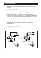
Thermostat Thermal cut-out Pressure switch Front cover Flow control valve To close: turn anticlockwise Multipoint 1.0 INTERNAL COMPONENTS 1.1 A pressure relief device (PRD) is designed into the handwash appliance, which complies with European standards. The PRD provides a level of appliance protection should an excessive build-up of pressure occur within the appliance. 1.2 DO NOT operate the handwash with a damaged spout or blocked sprayplate, which can cause the PRD to operate.
2.4 2.5 2.6 2.7 2.8 2.9 2.10 2.11 2.12 2.13 2.14 2.15 2.16 2.17 2.18 2.19 4 DO NOT operate the appliance if: 1. Water ceases to flow during use. 2. Water has entered inside the unit because of an incorrectly fitted cover. 3. If the appliancet is damaged. ISOLATE the electrical and water supplies before removing the cover. ISOLATE the electrical and water supplies BEFORE proceeding with installation or servicing.
CAUTION 2.22 This appliance must be earthed. 2.23 Fuses do not give personal protection against electric shock. To enhance electrical safety a 30mA residual current device (RCD) should be installed in all electric handwash circuits. This may be part of the consumer unit, or a separate unit. 2.24 Ensure that all terminal block connections are sufficiently tight. 2.25 Switch off appliance immediately and isolate if water ceases to flow during use. 2.26 Other electrical equipment e.g.
3.0 SITE REQUIREMENTS 3.1 3.2 3.3 WARNING The handwash must not be positioned where it will be subjected to freezing conditions. WATER REQUIREMENTS The installation must be in accordance with Water Regulations. To ensure activation of the heating elements, the handwash must be connected to a mains water supply with a minimum running pressure of 0.1 MPa (1 bar) and a maximum static pressure of 0.7 MPa (7 bar). If static pressure exceeds 0.
The appliance must be earthed IMPORTANT - INSTALLATION TO BE DONE BY A COMPETENT INSTALLER 3.5 The installation supply cable and circuit protection must conform to BS 7671. 3.6 Before making any sort of electrical connection, ensure that no terminal within the circuit is live. If in any doubt SWITCH OFF the whole installation at the consumer unit. 3.7 The handwash must only be connected to a 230-240V ac supply. 3.
3.11 To obtain full advantage of the power provided by the handwash, use the shortest cable route possible from the consumer unit to the handwash. 3.12 If your consumer unit has a rating below 80A or, if there is no spare fuse way, then the installation will not be straightforward and may require a new consumer unit. A qualified electrician should install the new consumer unit. It may be necessary to contact your electrical supplier to upgrade your supply. CAUTION 3.
Multipoint 4.0 CONSIDERATIONS BEFORE FITTING IMPORTANT - INSTALLATION TO BE DONE BY A COMPETENT INSTALLER 4.1 The appliance must be mounted on a flat surface, which covers the full width and length of the backplate. It is important that the wall surface is flat otherwise difficulty may be encountered when fitting the cover. 4.2 Ensure that the handwash is positioned over the basin, because if the PRD operates water will eject from the bottom of the appliance. 4.
4.9 PIPE ENTRY Plumbing entry can be from the rear (preferred) or from the bottom. The backplate has a cut out position to suit 15mm pipe.When opting for bottom entry make cut out before fitting backplate to the wall - see Figure 6. Figure 6 Plumbing cut-out Make cut-out using sharp knife 5.0 FITTING INSTRUCTIONS 5.1 TURN OFF water and electrical supply. 5.2 The appliance is designed for bottom and rear entries of water and electric cable.
PIPE CONNECTION The outlet spout can be removed to ease installation. The handwash has been designed for a 15mm water pipe using the pushfit connection - see Fig. 11 on page 12. 5.10 Decide where to connect the cold water mains feed to the handwash. Ensure that the pipe you have selected is not a gas pipe or a hot water pipe. Chrome and stainless steel pipe is not recomended. 74 196.5 235 151 Multipoint 5.8 5.9 Inlet water connection 19.
5.11 An isolating stopvalve MUST be incorporated to the main water supply to comply with Water Regulations - see Fig. 4. 5.12 Cut all necessary pipework to length with a pipecutter and not a hacksaw. This will minimise the swarf and prevent damage to the sealing o-ring in the pushfit fitting - see Figure 10. 35mm Figure 10 Cutting pipes Bottom entry Rear entry Copper compression fitting shown - push fit stem elbow can be used. Figure 11 Pipe connection 5.
6.0 ELECTRICAL CONNECTIONS 6.2 6.3 6.4 6.5 6.6 6.7 6.8 WARNING This appliance must be earthed. Multipoint 6.1 CAUTION When working on electrical components ensure they are NOT LIVE. If in any doubt, SWITCH OFF THE ELECTRICITY SUPPLY. A double-pole isolating switch having a contact separation of 3mm in each pole MUST be incorporated to the circuit - see paragraphs 4.10 and 4.11. The cable entry should have been decided before fitting the backplate - see 5.8.
7.0 COMMISSIONING 7.1 7.2 7.3 7.4 7.5 7.6 7.7 7.8 14 NOTE: The first operation of the handwash is intended to ensure the heater unit contains water before the appliance is switched on. Before turning on the electricity and mains water to the handwash, ensure the control knob is turned fully clockwise.
8.3 8.4 8.5 IMPORTANT Do not attempt any electrical or plumbing work unless you are competent to do so. If you still cannot solve the problem, please contact Santon. INSPECTION It is advisable that, in the interests of safety, the handwash and its electrical installation is checked by a competent electrician, at least every two years. SYMPTOM POSSIBLE CAUSE A. Water supply turned off B. Unit frozen 1. No water flows with valve open 2. Water too cold 3. Water too hot 4.
9.0 MAINTENANCE 9.1 9.2 It is recommended that the handwash casing be cleaned using a soft cloth and that the use of abrasive or solvent cleaning fluids be avoided. It is advisable that before cleaning, the isolating switch is turned off, thus avoiding accidental operation of the handwash. IMPORTANT IT IS MOST IMPORTANT TO KEEP THE SPRAYPLATE CLEAN IN ORDER TO MAINTAIN THE PERFORMANCE OF THE HANDWASH. The hardness of the water will determine the frequency of cleaning.
1 2 3 4 Multipoint Guarantee This product is guaranteed against faulty materials and manufacture for a period of two years from the date of purchase provided that: The unit has been installed by a competent person in accordance with the Installation, User Instructions, all relevant Codes of Practice, Regulations in force at the time of Installation and that all necessary controls and safety valves have been fitted correctly.
Notes: _________________________________________________________ 18
Notes: Multipoint _________________________________________________________ 19
Spares Stockists SPD Units 9 & 10 Hexagon Business Centre Springfield Road, Hayes Middlesex, UB40 0TY Tel: 020 8606 3567 Sales Tel: Sales Fax: Hurricane Way, Sales Email: Norwich, Service Tel: Norfolk, NR6 6EA. Service Fax: www.santon.co.uk ServiceEmail: 20 © 2008 (08700) 603263 (08700) 600403 sales@santon.co.uk (08701) 600126 (08701) 600181 santonservice@ heateam.co.