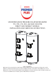
UNVENTED MAINS PRESSURE SOLAR WATER HEATER 170, 190, 210, 250, 260 AND 300 LITRE DIRECT AND INDIRECT MODELS INSTALLATION AND SERVICING INSTRUCTIONS PACK CONTENTS Premier Plus unvented solar water heater incorporating immersion heater(s) and thermal controls Factory fitted temperature/pressure relief valve Cold water combination valve Expansion vessel Expansion vessel mounting bracket Tundish Motorised valve (indirect models only) Compression nuts and olives Immersion heater spanner Installat
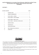
SANTON PREMIER PLUS SOLAR INSTALLATION AND SERVICING INSTRUCTIONS. PLEASE LEAVE THIS MANUAL WITH THE UNIT FOR FUTURE REFERENCE. CONTENTS SECTION CONTENT PAGE 1 INTRODUCTION .................................................................... 4 2 GENERAL REQUIREMENTS 3 INSTALLATION - GENERAL ......................................................... 6 4 INSTALLATION - SOLAR PRIMARY ............................................ 13 5 INSTALLATION - DIRECT UNITS.......................................
IMPORTANT: PLEASE READ ALL THESE INSTRUCTIONS BEFORE COMMENCING INSTALLATION THE INFORMATION CONTAINED IN THESE INSTRUCTIONS DETAILS HOW TO CONNECT THE PREMIER PLUS SOLAR CYLINDER TO A SOLAR PRIMARY CIRCUIT. OTHER CONTROLS WILL BE NECESSARY TO PROVIDE CONTROL OVER THE SOLAR PRIMARY CIRCUIT, REFER TO THE INSTRUCTIONS SUPPLIED WITH THE SOLAR CONTROLS AND ANCILLARY EQUIPMENT FOR DETAILS OF HOW TO INTEGRATE THEM WITH THE PREMIER PLUS SOLAR CYLINDER.
1.0 INTRODUCTION The Santon Premier Plus Solar is a purpose designed unvented solar water heater. The unit has a stainless steel inner vessel which ensures an excellent standard of corrosion resistance. The outer casing is a combination of resilient thermoplastic mouldings and corrosion proofed steel (Plastisol) sheet. All Premiers are insulated with CFC/HCFC free polyurethane foam to meet the latest European heat loss requirements (see Table 3).
2.0 GENERAL REQUIREMENTS 2.1 COMPONENTS SUPPLIED 1. Premier Plus unvented solar water heater incorporating immersion heater(s) and thermal controls 2. Factory fitted temperature/pressure relief valve 3. Cold water combination valve. 4. Expansion vessel and mounting bracket. 5. Tundish. 6. Motorized valve (indirect models only). 7. Compression nuts and olives 8. Immersion heater key spanner 2.2 SITING THE UNIT The Santon Premier Plus Solar must be installed vertically.
3.0 INSTALLATION – GENERAL 3.1 PIPE FITTINGS All pipe fittings are made via 22mm compression fittings directly to the unit. The fittings are threaded 3/4”BSP male parallel should threaded pipe connections be required. 3.2 COLD FEED A 22mm cold water supply is recommended however, if a 15mm (1/2”) supply exists which provides sufficient flow this may be used (although more flow noise may be experienced).
FIG. 1 Cold Water Combination Valve Expansion valve Expansion valve outlet (15mm) FIG. 2 Secondary circulation connection Cold mains connection (22mm) Outlet connection (22mm) Pressure reducing valve cartridge (3.5bar) 29 FIG. 3 General Dimensions and features 1. SOLAR PRIMARY RETURN 2. SOLAR PRIMARY FLOW 3. AUXILLARY BOILER RETURN (INDIRECT MODELS ONLY) 4. AUXILLARY BOILER FLOW (INDIRECT MODELS ONLY) 5. T&P VALVE 6. SECONDARY RETURN 7. BOOST IMMERSION HEATER (DIRECT MODELS ONLY) 8.
INSTALLATION - DISCHARGE It is a requirement of Building Regulation G3 that any discharge from an unvented system is conveyed to where it is visible, but will not cause danger to persons in or about the building. The tundish and discharge pipes should be fitted in accordance with the requirements and guidance notes of Building Regulation G3. The G3 Requirements and Guidance section 3.50 - 3.63 are reproduced in the following sections of this manual.
(D2) to be connected. 3.
Table 4 Va lve outle t size Minim um size of discha rge pipe D1 G1/2 15mm G3/4 22mm G1 28mm Minim um size of discha rge pipe D2 from tundish Ma x im um re sista nce a llow e d, e x pre sse d a s a le ngth of stra ight pipe (I.E . no e lbow s or be nds) Re sista nce cre a te d by e a ch e lbow or be nd 22mm 28mm 35mm 28mm 35mm 42mm 35mm 42mm 54mm up to 9m up to 18m up to 27m up to 9m up to 18m up to 27m up to 9m up to 18m up to 27m 0.8m 1.0m 1.4m 1.0m 1.4m 1.7m 1.4m 1.7m 2.
FIG. 5 Typical installation - schematic Fig 6 - Direct Electrical connections (schematic) Direct Wiring Layout Fig 7 - Adjustment details THERMAL CUT-OUT RESET BUTTON SPINDLE POSITIONS = MINIMUM TEMP 10 °C N 1.
Fig. 8 Control Housing Details Element Connections Indirect control wiring 1 2 3 L N 1.5mm² 3 Core HOFR sheathed cable Fig.
4.0 INSTALLATION - SOLAR PRIMARY 4.1 CONNECTION TO PRIMARY CIRCUIT The lower (solar) coil of the Premier Plus Solar must be connected to a fully pumped solar primary circuit. The connections are suitable for 22mm copper pipe direct to the compression fittings provided. The connections are also threaded 3/4” BSP male parrallel should BSP be required. The solar primary circuit should have its own dedicated circulating pump and safety controls which must be installed as per the manufacturers’ instructions. 4.
6.0 INSTALLATION - AUXILLARY HEATING COIL 6.1 PLUMBING CONNECTIONS Indirect units require the following pipework connections. • Cold water supply to and from inlet controls. • Outlet to hot water draw off points. • Discharge pipework from valve outlets to tundish • Connection to the auxillary primary circuit. Primary connections are 22mm compression. However, 3/4”BSP parallel threaded fittings can be fitted to the primary coil connections if required. 6.2 ELECTRICAL SUPPLY (FIG.
Figure 10 - 2 port valve in conjunction with a 3 port mid-position valve system (“Y” Plan) PREMIERPLUS INDIRECT THERMAL CONTROLS (SUPPLIED FITTED) PROGRAMMER KEY Bl Br G O GY DHW HTG L N 1 2 HTG ON DHW ON DHW OFF 4 5 6 PREMIERPLUS (DHW) 2-PORT VALVE (SUPPLIED) Bl Br G O GY 1 2 3 7 8 9 10 11 12 13 14 15 16 Bl W G BLUE BROWN GREY ORANGE GREEN/YELLOW DOMESTIC HOT WATER HEATING 3 WIRING CENTRE (SUPPLIED) L N 1 3 2 ROOM STAT O GY N 3-PORT MID POSITION VALVE N L L PUMP BOILER
7.0 COMMISSIONING 7.1 FILLING THE UNIT WITH WATER • Check Expansion Vessel pre-charge pressure. The vessel is supplied pre-charged to 3.5 bar to match the control pressure of the Pressure Reducing Valve. The pre-charge pressure is checked using a car tyre gauge by unscrewing the plastic cap opposite the water connection. • Check all connections for tightness including the immersion heater(s). An immersion heater key spanner is supplied for this purpose. • Ensure the drain cock is CLOSED.
8.0 MAINTENANCE 8.1 MAINTENANCE REQUIREMENTS Unvented hot water systems have a continuing maintenance requirement in order to ensure safe working and optimum performance. It is essential that the relief valve(s) are periodically inspected and manually opened to ensure no blockage has occurred in the valves or discharge pipework. Similarly cleaning of the strainer element and replacement of the air in the expansion vessel will help to prevent possible operational faults.
When water flows from the hot tap allow to flow for a short while to purge air and flush through any disturbed particles. Close hot tap and then open successive hot taps in system to purge any air. When completely full and purged check system for leaks. The heating source (immersion heater(s), boiler or solar primary circuit) can then be switched on. 8.
9.0 USER INSTRUCTIONS 10.1 WARNINGS IF WATER ISSUES FROM THE TEMPERATURE/PRESSURE RELIEF VALVE ON THE SANTON PREMIER PLUS SOLAR SWITCH OFF ELECTRICAL SUPPLY TO THE IMMERSION HEATER(S) (DIRECT UNITS),SHUT DOWN THE BOILER (INDIRECT UNITS) AND SHUT DOWN THE SOLAR PRIMARY CIRCUIT. DO NOT TURN OFF ANY WATER SUPPLY. CONTACT A COMPETENT INSTALLER FOR UNVENTED WATER HEATERS TO CHECK THE SYSTEM. DO NOT TAMPER WITH ANY OF THE SAFETY VALVES FITTED TO THE SANTON PREMIER PLUS SYSTEM.
10.0 Fault Finding & Servicing IMPORTANT • After servicing, complete the relevant service interval record section of the Benchmark Checklist located on page 24 and 25 of this document. • Servicing should only be carried out by competent persons in the installation and maintenance of unvented water heating systems. • Any spare parts used MUST be authorised Santon parts. • Disconnect the electrical supply before removing any electrical equipment covers.
Table 5 - Fault finding chart Fault No hot water flow Possible Cause Remedy Mains water supply off Check and open stop cock Strainer blocked Turn off water supply.
Table 6 - Spares List DESCRIPTION 1 Immersion heater (lower) 95 606 984 2 Immersion heater (upper) 95 606 986 3 Immersion heater gasket 95 611 822 4 Immersion heater backnut 95 607 869 5 Immersion heater key 95 607 861 6 Tundish 95 605 838 7 Expansion valve - 6bar 95 605 899 8 Cold water combination valve complete 95 605 897 9 Cold water combination body 95 605 900 10 Pressure reducing valve cartridge 3.
Fig.
Fig.
11.0 GUARANTEE WARNING: Should the factory fitted temperature and pressure relief valve be tampered with or removed your guarantee will be invalidated. Neither the Distributor nor Manufacturer shall be responsible for any consequential damage howsoever caused. Guarantee Terms Santon guarantees the PremierPlus against faulty manufacture or materials for a period of 2 year from the date of purchase including parts and labour.
Spares Stockists Electric Water Heating Co. 2 Horsecroft Place Pinnacles Harlow Essex CM19 5BT Tel: 0845 0553811 E-Mail: sales@ewh.co.uk SPD Special Product Division Units 9 & 10 Hexagon Business Centre Springfield Road Hayes Middlesex UB40 0TY Tel: 0208 5730574 Parts Center Network 65 Business Park Bentley Wood Way Burnley Lancashire BB11 5ST Tel: 01282 834403 www.partscenter.co.