Installation and User Instructions Models: SP2.5, SP5.0, SP7.5 Multipoint SPEEDIBOIL Please read and understand these instructions before starting work. Please leave this leaflet with the user following installation. WARNING This Boiling Water Heater must only be installed by qualified persons. 36006034 Issue 2.
INTRODUCTION Thank you for purchasing a Santon Speediboil . The Boiling water heater is manufactured to the highest standards and has been designed to meet all the latest relevant safety specifications. This Santon water heater must be installed (Sections 1-5), commissioned (Section 6) and maintained (Sections 7-8) by a competent person. Please read and understand these instructions prior to installing your Santon water heater.
CONNECTIONS Inlet connection -15mm ext. diameter Water entry point - bottom and rear Cable entry point - bottom and rear ELECTRICAL Model numbers 2.5kW - Speediboil 2.5ltr - 94 200 001 2.5kW - Speediboil 5.0ltr - 94 200 002 2.5kW - Speediboil 7.5ltr - 94 200 003 Electrical rating 2.3/2.5kW@230/240V Nominal capacities Model SP2.5 2.5 litres Model SP5.0 5.0 litres Model SP7.5 7.5 litres Weight (full) Model SP2.5 8.4kg Model SP5.0 11.8kg Model SP7.5 15.
1.0 IMPORTANT INSTALLATION POINTS 1.1 The Speediboil stores and dispenses water at or close to boiling point at all times it is switched on. Due caution must be taken when choosing a location for the product to minimise misuse. Locate the unit over a draining board NOT over the sink or basin. 1.2 Push fit connectors DO NOT grip chromed or stainless pipe. 1.3 The Speediboil is a vented water heater. The vent pipe must never be blocked or obstructed, it must be a minimum of 15mm outside diameter pipe.
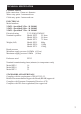
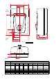
2.0 INSTALLATION - MOUNTING 2.3 2.4 2.5 2.6 2.7 The Speediboil must be vertically wall mounted using the bracket supplied. Fig.1 details the outside dimensions of the Speediboil unit. It is recommended that the unit is positioned above the draining board. If this is not possible consideration should be given to any spillages that may occur under the appliance. The heater should be positioned at a height to suit the items being filled (flasks, pans, cups etc.).
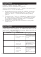
B N M Fixing Bracket A 30 L F K Fixing Hole O 250mm approx D J E C Worktop I G H Figure 1 MODEL SP2.5 SP5.0 SP7.
Multipoint SP2.5 SP5.0 SP7.5 M L K N I J O CABLE FIXING FIXING BRACKET BRACKET BRACKET OUTLET ENTRY POINT POINT 96 169 50 59 342 152 52.5 117 67 401 84 217 163 61 61 117 401 67 84 217 225 3.0 INSTALLATION - WATER SUPPLY 3.1 Select appropriate push fit connector for chosen entry position: Bottom entry water 15mm x 15mm 90º elbow. Rear entry water - 15mm x 15mm straight. Note: stainless or chromed pipes DO NOT provide secure connections with push fit fittings (use copper pipe at joints). 3.
5.0 INSTALLATION - ELECTRICAL REQUIREMENTS WARNING: 5.1 This appliance must be earthed. 5.2 The installation, supply cable and circuit protection must conform to the latest BS7671 ‘Requirements for electrical installations’ (IEE Wiring Regulations). 5.3 The appliance must only be connected to a 230/240 V ac supply. A double pole isolating switch, with a contact separation of at least 3mm in both poles, must be incorporated in the electrical supply. The supply should be fused 13Amp. 5.
Multipoint 6.0 COMMISSIONING 6.1 The electronic control system of the Speediboil has a self commissioning and calibration function. Once the heater is installed and all services have been connected the appliance should require no further adjustment before use. 6.2 Check that all electrical, water and vent pipe connections have been made and are secure. 6.3 Replace the cover and secure with the fixing screws. Ensure the tank discharge tube is centrally located in the outlet spout.
7.0 MAINTENANCE NOTE: Maintenance must be carried out by competent persons. Competent - i.e. Trained, experienced, qualified. Disconnect the electrical supply before removing the cover. WARNING: Electronics control by switching ‘n’ (neutral), in some instances neutral terminations will be at 230 volts with respect to earth. 7.1 7.2 7.3 The Speediboil incorporates an electronic scale conditioning function which will reduce the rate of scale deposition in hard water areas.
Unit does not fill after commisioning POSSIBLE CAUSE 1. Level sensor fault 2. Solenoid valve fault 3. Electronic control fault 4. Low water pressure Unit does not heat after commisioning 1. Element fault 2. Electronic control fault 3. Control thermistor fault - short circuit Water flows from vent and primary cutout activate 1. Solenoid valve fault 2. Level sensor fault 3. Electronic control fault 4. Low water pressure Steam from vent pipe and primary cutout operates 1.
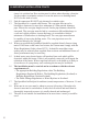
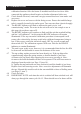
9.0 SPARE PARTS The following comprehensive list of spare parts is available for your Santon Speediboil water heater. Please refer to the rating label on the right hand side of your heater before ordering to ensure the correct spare parts are obtained. DO NOT REPLACE WITH PARTS NOT RECOMMENDED BY SANTON THIS WILL INVALIDATE YOUR GUARANTEE AND MAY RENDER THE INSTALLATION DANGEROUS. 1. Element assembly (incorporating start dry cutout)............................. 95 607 952 2.
13 13 17 11 Figure 3: Spares 4 7 23 8 19 5 3 9 10 6 18 14 14 13 16 21 14 20 2 1 22 Multipoint 15 14 13 12
10.0 USER INSTRUCTIONS 10.1 Once installed the filling and the heating cycles of the Speediboil are completely automatic. 10.2 To dispense water, place a suitable container under the outlet spout and pull the tap handle down and towards (or pushed away) the user. The water dispensed will at all times be boiling or close to boiling point so due caution must be taken when using the product. 10.3 The tap handle is spring loaded so that when released it will spring back to the “off” position (no flow).
1 2 3 4 Multipoint Guarantee This product is guaranteed against faulty materials and manufacture for a period of two years from the date of purchase provided that: The unit has been installed by a competent person in accordance with the Installation, User Instructions, all relevant Codes of Practice, Regulations in force at the time of Installation and that all necessary controls and safety valves have been fitted correctly.
Spares Stockists Electric Water Heating Co. 2 Horsecroft Place, Pinnacles Harlow, Essex, CM19 5BT Tel: 0845 0553811 E-Mail: sales@ewh.co.uk SPD Units 9 & 10 Hexagon Business Centre Springfield Road, Hayes Middlesex, UB40 0TY Tel: 020 8606 3567 Parts Center Tel: 0845 270 9801 www.partscenter.co.uk Newey & Eyre Specialist Products Division Please contact your local branch UK Spares Ltd. Tower Lane, Warmley Bristol, BS30 8XT Tel: 0117 961 6670 William Wilson Ltd.