
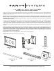
TV Mount User's Manual
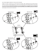


Step 3: Add the Vise Assemblies to the Monitor Brackets:
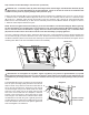
NOTE: Do not overtighten the 1/4-20 Nut (M). The Vise Assembly (F) should be able to rotate freely around the
Carriage Bolt (L).
Place the Vise Assembly (F) into the Monitor Bracket (E) so that the two Jaws point toward the set of 1” diameter holes
and the Allen Bolt is facing away from the television. Place a 2” Carriage Bolt (L) through the square hole in the side of the
Monitor Bracket, and the Vise Assembly; then, through the square hole in the other side of the Monitor Bracket. Thread and
tighten a 1/4-20 Nut (M) onto the end of the 2” Carriage bolt. Repeat this step for the bottom of the Monitor Bracket; then,
repeat this process for the second Monitor Bracket. See Diagram 3 and Vise Detail.
Vise Detail
Diagram 3
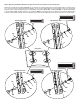
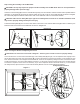
Step 4: Attach the Arm Assembly to the Television
Align each Vise Assembly (F) so that a 1” Diameter Tube (D) will pass through the 1” round hole in the Monitor Bracket (E)
and between the jaws of the Vise Assembly. Insert a 1” Diameter Tube through the top hole in the rst Monitor Bracket.
Repeat this step for the Bottom hole in the same Monitor Bracket. See Diagram 4a for assistance.
Diagram 4a
Jaws
1” Dia.
Hole
Allen
Bolt
L
F
E
M
F
F
D
E
E
Step 4: Attach the Arm Assembly to the Television (Continued on next page.)