
TV Mount User's Manual
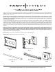


Step 4: Attach the Arm Assembly to the Television (Continued)
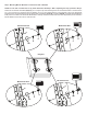
CAUTION: The 1” Diameter Tubes (D) must extend beyond the outside edges of both Monitor Brackets (E) and
the Allen Bolts in all 6 Vise Assemblies (F) must be tightened. Failure to do this will result in an installation that
unstable and may result in property damage and/or personal injury.
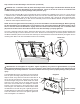
Position the Arm Assembly (B) so the hook shaped tab shown in Detail View of Diagram 4b is on the top. Line up the two
1” diameter holes in the Monitor Bracket (E) at the other end of the Arm Assembly with the with the 1” Diameter Tubes
(D). Push the 1” Diameter Tubes through the bracket on the Arm Assembly; then, through the other Monitor Bracket.
Make sure the Vise Assemblies (F) on both the Arm Assembly and the second Monitor Bracket are aligned so that the
1” Diameter Tubes will pass between the jaws.
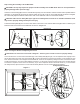
NOTE: Do not over-tighten the Vise Assembly (F), or the Vise Assemblies in the Arm Assembly (B). When tightening
the Vise Assemblies, turn the Allen Bolt in until resistance is felt; then, tighten the Allen Bolt approximately 1 & 1/2
turns or until the head of the Allen Bolt is slightly above the surface of the Vise Assembly. The 1” Diameter Tubes
(D) must not be able to move from side-to-side when the Vise Assembly is properly tightened.
Once the 1” Diameter Tubes are in place, tighten the allen bolts on the 4 Vise Assemblies in the two Monitor Brackets with
the 3/16 Allen Key (K) to lock the television to the mount. Slide the Arm Assembly into the desired position between the
two Monitor Brackets (Sanus recommends Arm Assembly be centered between the Monitor Brackets) and tighten the two
remaining Allen Bolts in the Vise Assemblies inside the Arm Assembly.
Detail View
Diagram 4b
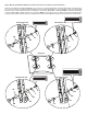
Step 5: Attach the Wall Plate: Wood Stud installation only.
CAUTION: Do not overtighten the Lag Bolts. Tighten Lag Bolts (I) only until the Lag Bolt Washer (J) is pulled
rmly against the Wall Plate (A). If there is a layer of drywall or other material, this drywall or other material may not
exceed 5/8 inch [15.8 mm] in thickness. Failure to heed this caution may result in property damage and/or personal
injury.
E
E
D
D
B
F
F
Tab
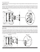
The Wall Plate (A) must be mounted to two wood studs at
least 12” apart. Use a high quality stud sensor to locate two
adjacent studs. Verify where the studs are located with an
awl or thin nail. Pre-drill a 2.5” deep hole in each stud at
the desired height using a 3/16” drill bit. Make sure these
holes are in the center area of the studs and level with
each other. Use the Wall Plate as a template to mark the
location of the second hole in each stud. Drill 2.5” deep
holes using the 3/16” drill bit in the marked location. Attach
the Wall Plate to the wall using four Lag Bolts (I) and four
Lag Bolt Washers (J). Make sure the Wall Plate is oriented
so the at surface in the center of the plate is against the
wall. See Diagram 5 for assistance.
Stud
Drywall cut away
to show studs.
A
J
I
Diagram 5