
User Manual


ENGLISH
Assembly Instructions for Model: VM1
Thank you for choosing Sanus Systems Vision Mount. This product is designed to
mount VESA 75/100 compatible LCD televisions up to 50 pounds onto a vertical wall.
It allows you to effortlessly tilt and swivel your new television up to 15° in either
direction without the use of tools. Check carefully to make sure there are no missing
or defective parts. Never use defective parts. Improper installation may cause dam-
age or serious injury. If you do not understand these directions, or have any doubts
about the safety of the installation, please call a qualied contractor or contact Sanus
at 800.359.5520 or www.sanus.com. We can quickly assist you with installation ques-
tions and missing or damaged parts. Replacement parts for Sanus products purchased
through authorized dealers will be shipped directly to you.
Required Tools: Drill with 3/16” bit, Phillips screw driver
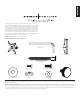
Parts and Hardware: *Not shown as actual size
(1) Allen Key - b
(1) Monitor Mount - a* (1) Wall Plate - c*
(2) Lag Bolt - d
(4) M4 x 10 Bolt - e (4) Knob Replacement Bolt - f
(1) Large Washer - g (1) Cap - h (1) Small Washer - i (1) Knob - j
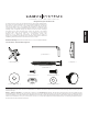
Step 1 - Attaching to the Television: Attach the Monitor Mount (a) to the back of your LCD television using the M4 x 10 Bolt (e) as shown in Diagram 1. Place 4 bolts through the
Monitor Mount and tighten snugly into the VESA bolt mounting pattern on the back of the television. Make sure the large side of the tapered hole on the Monitor Mount faces toward
the bottom of the television.
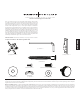
Step 2 - Attaching to the Wall: Hardware for wood stud mounting is provided. For all other mounting applications contact a local contractor or hardware store. Use a high quality
stud sensor to locate a stud. It is a good idea to verify the stud location with an awl or thin nail as shown in Diagram 2a. Use the Wall Plate (c) as a template to mark the two hole loca-
tions on the wall. Make sure these holes are aligned vertically and centered over the stud. Pre-drill the two holes to a depth of 2.5” using a 3/16” drill bit. Attach the Wall Plate to the
wall using the two Lag Bolts (d) as shown in Diagram 2b. Tighten the Lag Bolts rmly with the Allen Key (b).