
User's Manual


53
TR
TR
TR
90478 2.4GHZ FH4T RADIO SYSTEM USER'S GUIDE
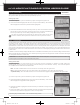
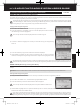
1) From within the BIND menu, scroll UP or DOWN to highlight the desired channel you
would like to change the Servo Operating Mode for. Choose from either [ST]:NOR
(Steering), [TH]:NOR (Throttle), [A1]:NOR (Auxiliary 1) or [A2]:NOR (Auxiliary 2).
02.BIND
(
BINDING, MODULATION TYPE AND SERVO OPERATING MODE
)
SYSTEM
IMPORTANT INFORMATION ABOUT SERVO OPERATING MODES:
If you're using Analog servos in your model, DO NOT use SHR or SSR Servo Operating Mode for those channels. Use the
NOR (Normal) Servo Operating Mode with Analog servos. Using SHR or SSR Servo Operating Mode with Analog servos can
result in poor performance or even damage to the servos or the receiver! In some cases, the servo may not operate at all.
Not all ESCs are compatible with SHR or SSR Servo Operating Modes. If your ESC does not operate correctly, change the
Servo Operating Mode to NOR (Normal) for that channel (or channels).
SHR and SSR Servo Operating Modes should only be used with Digital servos. While the SHR Servo Operating Mode can be
used with any brand of Digital servo, the SSR Servo Operating Mode should ONLY be used with Airtronics SRG Digital servos.
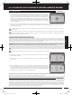
2) Press the ENTER key, then scroll UP or DOWN to choose the desired Servo Operating
Mode option for that channel.
SERVO OPERATING MODE setting range is NOR, SHR and SSR. The default setting is
NOR. SSR Operating Mode is not supported when the FH3 or FH3F Modulation Type
is selected. No Servo Operating Modes are supported when the FH2 Modulation Type
is selected.
Binding the Transmitter and Receiver:
To Bind the transmitter and receiver, please see the Transmitter and Receiver Binding section on page 16. Prior to Binding the
transmitter and receiver, make sure to choose the desired Modulation Type that matches the receiver you're using. Servo
Operating Mode can be changed prior to Binding the transmitter and receiver, or after the Binding process.
SYSTEM
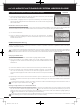
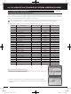
Trm1 - Steering Trim
Trm2 - Throttle Trim
Trm3 - Steering Dual Rate
Trm4 - Brake Dual Rate
Sw1 - Telemetry Logger ON/OFF
Sw2 - Timer ON/OFF
Dial Knob - Auxiliary 1 Channel 3
Auxiliary Lever - Auxiliary 2 Channel 4
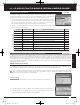
The Key Assignments function allows you to assign different functions to each of the two Push-Button Switches, the four Trim
Switches, the Dial Knob and the Auxiliary Lever. In addition, the ON/OFF behavior of some Push-Button Switch functions can
be changed. The Key Assignments function also allows you to change the Direction of Travel and the Trim Resolution of the
four Trim Switches and the Rotary Dial. This allows you to fine-tune the movement of the servos when the Trim Switches are
pressed and the Rotary Dial is turned.
03.KEY ASSIGN
(
KEY ASSIGNMENTS
)
SYSTEM
Trim Switch
(Trm1)
Dial Knob
Push-Button
Switch (Sw1)
Trim Switch
(Trm2)
Trim Switch (Trm3)
Trim Switch
(Trm4)
Auxiliary Lever
Push-Button
Switch (Sw2)
MT-4S User's Guide.indd 53 2015/10/27 14:39:10