
User's Manual


3DJH
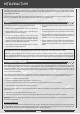
DRIVING POSITION ADJUSTMENTS
TRIM RING POSITION
The position of the digital trim ring can be repositioned to
better suit your taste. Five different positions are available.
Trm 1 is factory set at the top center position.
5HPRYHWKH0VRFNHWKHDGFDSVFUHZVRQHDFKVLGH
of the transmitter using a 3mm hex wrench.
'HWDFK WKH JULS GRZQZDUG IURP WKH XSSHU WUDQVPLWWHU
unit. Be careful to avoid damaging the lead wires that
are connected on both units.
5HPRYH WKH WKUHH0VRFNHWKHDGFDSVFUHZV IURP
WKH EDFNVLGH RI WKH WULP ULQJ LH EHKLQG WKH VWHHULQJ
wheel as shown on the photo) using a 2mm hex wrench.
4) Rotate the trim ring to the desired position. The trim
SULQJFDQEHSRVLWLRQHGLQRQHRI¿YHGLIIHUHQWSRVLWLRQV
Set the trim ring at the desired position, then retighten
WKHWKUHH0VRFNHWKHDGFDSVFUHZV
$IWHU UHVHWWLQJ WKH WULPPHU SRVLWLRQ DWWDFK WKH XSSHU
WUDQVPLWWHUXQLWEDFNLQWRSODFH7LJKWHQXVLQJDPP
KH[ ZUHQFK DQG WZR PP KH[ VRFNHW KHDG FDS
screws per side.
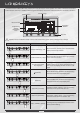
The steering wheel position can be changed from the right
VLGHWRWKHOHIWVLGHWRDFFRPRGDWHOHIWKDQGHGXVHUV
5HPRYHWKH0VRFNHWKHDGFDSVFUHZVRQHDFKVLGH
of the transmitter using a 3mm hex wrench.
'HWDFK WKH JULS GRZQZDUG IURP WKH XSSHU WUDQVPLWWHU
unit. Be careful to avoid damaging the lead wires that
are connected on both units.
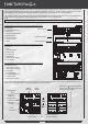
6HW WKH /HIW5LJKW VHOHFWRU VZLWFK WR / ORFDWHG DERYH
7UPDQG7UP
5RWDWHWKHJULSE\GHJUHHV
$IWHU URWDWLQJ WKH JULS DOLJQ WKH XSSHU WUDQVPLWWHU XQLW
DQG UHLQVWDOO LW XVLQJ WKH WZR 0 VRFNHWKHDG FDS
screws.
The transmitter ships with the steering wheel on the
ULJKWVLGHRIWKHWUDQVPLWWHUIRUULJKWKDQGHGXVHUV
STEERING WHEEL POSITION