
User's Manual Part 1


8
T R
Antenna: Transmits the signal from the transmitter to the receiver in the model. Never touch the Antenna during use. Doing so
may result in a weakened RF signal or complete loss of control of your model.
Antenna Reception Wire: The portion of the receiver antenna that receives the transmitter signal. The Antenna Reception Wire
should never be bent or it could be damaged and limit the range of your model.
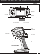
Use the diagrams in this section to make receiver connections and to familiarize yourself with the RX-472 4-Channel 2.4GHz
FH4T Super Response receiver included with your MT-4S radio control system. Descriptions of the features can be found in the
Transmitter and Receiver Features Descriptions
section below and on the next page.
If using the Sanwa Super Vortex ZERO or other SSL compatible ESC, plug the ESC into the BATT/SSL slot, otherwise
SSL features and telemetry data will not be available. All other ESC's should be plugged into the CH 2 TH port.
The receiver's Nominal Input Voltage is 3.7 to 7.4 volts. A 2 cell LiPo or LiFe battery pack can be used to power the receiver
without the use of a voltage regulator. In addition, this allows you to take advantage of the Higher torque and speed
provided by using 7.4 volt digital servos.
Use a 2 cell LiPo or LiFe battery pack ONLY if your servos are rated to handle the Higher voltage.
• We suggest binding the transmitter and receiver and making all receiver connections to check for correct
operation prior to mounting the receiver in your model.
• The receiver should be mounted as far away from any electrical components as possible. When routing
the antenna, avoid contact with any carbon or metal chassis components. Contact between metal or
carbon parts can result in electrical noise, which can adversely effect receiver performance and possibly
result in runaway operation and result in damage to your model.
• Route the receiver antenna up through a plastic tube so that it is in the vertical position. Do not bend the reception wire.
Reception performance decreases if the reception wire is bent. Do not pull on the antenna with force. Do not cut or extend
the antenna. The coaxial cable can be bent into gentle curves, however, do not bend the coaxial cable acutely, or repeatedly
bend it, or the antenna core can be damaged.
• To protect the receiver from vibration and other damage, we recommend wrapping the receiver in shock absorbing foam
or using double-sided foam tape when installing it in your model.
As a safety precaution, set your model on a stand so the wheels are off the ground before turning on your radio control
system or connecting your motor for the first time.
Bind Button
= Signal
= Positive
= Negative
Bind LED
Coaxial Cable
Antenna
Reception Wire
Steering
Channel 1
Throttle
Channel 2
Auxiliary 1
Channel 3
Auxiliary 2
Channel 4
On/Off Switch
'AA' Dry Cell Battery Holder,
4.8v to 7.4v Ni-Cd/Ni-MH Battery Pack or
2S LiPo/LiFe Battery Pack
On/Off Switch
To Battery
To Motor
ESC
Throttle
Channel 2
Glow/Gas
Setup
ESC
Setup
Antenna Tube
Coaxial Cable
Antenna
Reception Wire
Bind LED Condition Indicator:
The Bind LED on the receiver can be used to determine receiver condition at a glance. The Bind LED will alert you to various
receiver conditions, as shown in the table below.
Blue
Blue
Red & Blue
Red
Receiving RF Signal
Binding Operation
Receiver Battery Fail Safe Activates
No RF Signal After Receiver Battery Fail Safe Activates
LED COLOR
RECEIVER STATUS
LED CONDITION
ON
Slow Flash/Fast Flash
Flash
ON
Optional Airtronics Super Vortex
ZERO ESC w/SSL