MAXSYM 400i SERVICE MANUAL FOREWORD CONTENTS HOW TO USE THIS MANUAL MECHANISM ILLUSTRATION 20120303
Homepage Contents Foreword This service manual contains the technical data of each component inspection and repair for the Sanyang MAXSYM 400i scooter. The manual is shown with illustrations and focused on “Service Procedures”, “Operation Key Points”, and “Inspection Adjustment” so that provides technician with service guidelines. If the style and construction of the motorcycle, MAXSYM 400i, are different from that of the photos, pictures shown in this manual, the actual vehicle shall prevail.
Homepage Contents How to Use This Manual This service manual describes basic information of different system parts and system inspection & service for Sanyang MAXSYM 400i scooter. In addition, please refer to the manual contents in detailed for the model you serviced in inspection and adjustment. The first chapter covers general information and trouble diagnosis. The second chapter covers service maintenance information. Th third to the twelfth chapter covers the engine and driving systems.
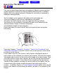
Homepage Contents Contents Page Content Index 1-1 ~ 1-16 General Information 1 2-1 ~ 2-16 Maintenance Information 2 3-1 ~ 3-6 Lubrication System 3 4-1 ~ 4-58 Fuel Injection System 4 5-1 ~ 5-4 Engine Removal 5 6-1 ~ 6-16 Cylinder Head / Valve 6 7-1 ~ 7-8 Cylinder / Piston 7 8-1 ~ 8-14 V-Belt Drive System 8 9-1 ~ 9-8 Final Drive Mechanism 9 10-1 ~ 10-4 AC Generator / Starting Clutch 10 11-1 ~ 11-8 Crankshaft / Crankcase 11 12-1 ~ 12-12 Cooling System 12 13-1 ~ 13-16 B
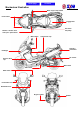
Contents Home page Mechanism Illustration Start / engine stop switch Front winker Luggage box Fuel tank / fuel pump Dimmer / winker / horn seat open / pass switch Main switch Coolant filler cap Taillight / rear winker Headlight Air cleaner Reserve tank cap Main stand Side stand Back mirror Front brake lever Rear brake lever Engine number Muffler
Homepage Contents 1.
To this chapter contents 1. General Information General Safety Carbon Monoxide Before you start the engine, make sure the place is well ventilated. Never start the engine in an unventilated place. If you have to start the engine in an unventilated place, an exhaust fume extractor is needed. Caution Exhaust fume contains toxic gas which may cause one to lose consciousness and even result in loss of life. Gasoline Gasoline is a low ignition point and explosive material.
To this chapter contents 1. General Information Before Servicing Always use SANYANG genuine parts and recommended oil. Using improper parts may cause damage to or destruction of the vehicle. Special tools are designed for removal and installation of component parts without damaging them. Using wrong tools may result in parts damage. When servicing this vehicle, use only metric tools.
To this chapter contents 1. General Information The length of bolts and screws for assemblies, cover plates or boxes is different from one another, be sure they are correctly installed. In case of confusion, Insert the bolt into the hole to compare its length with other bolts, if its length out side the hole is the same with other bolts, it is a correct bolt. Bolts for the same assembly should have the same length.
To this chapter contents 1. General Information Lubricate the rotation face with specified lubricant on the lubrication points before assembling. After service completed, make sure all connection points is secured. Battery positive (+) cable should be connected firstly. And the two posts of battery have to be greased after connected the cables. Check if positions and operation for installed parts is in correct and properly. Make sure service safety each other when conducting by two persons.
To this chapter contents 1. General Information When separating a connector, it locker has to be unlocked firstly. Then, conduct the service operation. Do not pull the wires as removing a connector or wires. Hold the connector body. Insert the terminal completely. Check if the terminal is covered by the boot. Do not let boot open facing up. Secure wires and wire harnesses to the frame with respective wire bands at the designated locations.
To this chapter contents 1. General Information Do not let the wire harness contact with rotating, moving or vibrating components as routing the harness. Protect wires or wire harnesses with electrical tape or tube if they contact a sharp edge or corner. Thoroughly clean the surface where tape is to be applied. Keep wire harnesses far away from the hot parts. Secure the rubber boot firmly as applying it on wire harness.
To this chapter contents 1. General Information Do not let the wire harness been twisted as installation. With sand paper to clean rust on connector pins/terminals if found. And then conduct connection operation later. Clean rust Wire harnesses routed along the handlebar should not be pulled too tight or have excessive slack, be rubbed against or interfere with adjacent or surrounding parts in all steering positions.
To this chapter contents 1.
To this chapter contents 1. General Information Torque Values The torque values listed in below are for more important tightening torque values. Please see standard values for those not listed in the table. Standard Torque Values for Reference Type 5 mm bolt、nut 6 mm bolt、nut 8 mm bolt、nut 10 mm bolt、nut 12 mm bolt、nut Tighten Torque 0.45~0.6kgf-m 0.8~1.2kgf-m 1.8~2.5kgf-m 3.0~4.0kgf-m 5.0~6.0kgf-m Type 5 mm screw 6 mm screw、SH nut 6 mm bolt、nut 8 mm bolt、nut 10 mm bolt、nut Tighten Torque 0.35~0.
To this chapter contents 1. General Information Frame Torque Values Item Mounting bolt for steering handle post Lock nut for steering stem Q’ty Thread Dia. (mm) Torque Value (Kg-m) Remarks 1 10 4.0~5.0 1 BC1 1.0~2.0 Steering top cone race 1 BC1 2.0~3.0 Front wheel axle nut 1 12 5.0~7.0 Rear wheel axle nut 1 16 11.0~13.0 Front cushion mounting bolt 4 10 3.5~4.5 Rear cushion upper connection bolt 1 10 3.5~4.5 Rear cushion under connection bolt 1 8 2.4~3.
To this chapter contents 1. General Information Troubleshooting A. Engine cannot be started or difficult to be started Check and adjustment Fault condition Probable causes Press the fuel injector feed pipe and confirm whether there is fuel in the feed pipe The fuel supply to the fuel injector is sufficient The fuel injector is not 1. Check the fuel amount in the fuel tank 2. Check if the fuel pipe and the vacuum tube are blocked or not 3. Malfunction of fuel pump relay or wiring 4.
To this chapter contents 1. General Information B. Engine runs sluggish (Speed does not pick up, lack of power) Check and adjustment Fault condition Probable causes Accelerate gradually and check engine RPM Engine RPM can be increased Engine RPM cannot be increased 1. 2. 3. 4. Clogged air cleaner Poor fuel supply Clogged exhaust pipe Clogged fuel injector Check ignition timing (Using ignition lamp) Correct ignition timing Incorrect ignition timing 1. Malfunction of ECU 2.
To this chapter contents 1. General Information C. Engine runs sluggish (especially in low speed and idling) Check and adjustment Fault condition Probable causes Check ignition timing (using ignition lamp) Normal 1. Incorrect ignition timing (malfunction of ECU or AC Abnormal Check for any air sucked in through the throttle body insulator gasket 1. Abnormal throttle body insulator gasket. 2. Abnormal throttle body installation Air sucked in No air sucked in 3. Abnormal inlet pipe gasket 4.
To this chapter contents 1. General Information E. CLUTCH AND DRIVING PULLEY FAULT CONDITION PROBABLE CAUSES Engine can be started but the vehicle cannot run 1. 2. 3. 4. 5. 6. Engine shuts down or trembles when the vehicle is running (rear wheel rotates during engine idling). Poor initial driving (poor climbing performance) Worn out or damaged drive belt Damaged movable drive face Damaged driven face spring Broken clutch weight Broken drive shaft groove Worn out or damaged transmission gear 1.
To this chapter contents 1.
Home page Contents 2.
To this chapter contents 2.
To this chapter contents 2. Maintenance Information Engine Oil Turn off engine, and park the vehicle in a flat surface with main stand. Check oil level with oil dipstick Do not screw the dipstick into engine as checking. If oil level is nearly low level, fill out recommended oil to upper level. Oil Change Caution Drain oil as engine warmed up so that to make sure oil can be drained smoothly and completely. Place an oil pan under the vehicle, and remove oil drain bolt.
To this chapter contents 2. Maintenance Information Gear Oil Oil inspection bolt Oil level inspection Park the vehicle on a flat surface with main stand. Turn off the engine. Gear Oil Change Remove oil inspection bolt. Remove drain plug and drain oil out. Install the drain plug after draining. Torque value: 0.8~1.2kgf-m Add gear oil to specified quantity from the inspection hole. Install the inspection bolt. Torque value: 1.0~1.4kgf-m Gear Oil Quantity: 330 c.c. when replacing it.
To this chapter contents 2. Maintenance Information Primary adjustment is conducted from bottom side. Loosen fixing nut, and adjust by turning the adjustment nut. Tighten the fixing nut, and check acceleration operation condition. Adjustment nut Air Cleaner Air Cleaner Element Remove 6 screws from the air cleaner cover. 6 screws Remove the air cleaner element. Caution The air cleaner element is made of paper so do not soap it into water or wash it with water.
To this chapter contents 2. Maintenance Information P.C.V. system Remove the plug from lower of the breather chamber hose. Release the dry internal deposit.
To this chapter contents 2. Maintenance Information Spark Plug Recommended spark plug: CR8E Remove luggage box Remove central cover. Remove spark plug cap. Clean dirt around the spark plug hole. Remove spark plug. Measure spark plug gap. Spark plug gap: 0.6~0.7 mm Carefully bend ground electrode of the plug to adjust the gap if necessary. Hold spark plug washer and install the spark plug by screwing it. Tighten the plug by turning 1/2 turn more with plug socket after installed. Tighten torque: 1.0~1.
To this chapter contents 2. Maintenance Information Cylinder Compression Pressure Warm up engine. Turn off the engine. Remove luggage box and central cover Remove spark plug cap and spark plug. Install compression gauge. Full open the throttle valve, and rotate the engine by means of starter motor. Caution Rotate the engine until the reading in the gauge no more increasing. Usually, the highest pressure reading will be obtained in 4~7 seconds. Spark plug cap Compression pressure: :12.
To this chapter contents 2. Maintenance Information Steering Handle Top Bearing Caution Check all wires and cables if they are interfered with the rotation of steering handle bar. Lift the front wheel out of ground. Turn handle from right to left alternative and check if turning is smoothly. If handle turning is uneven and bending, or the handle can be operated in vertical direction, then adjust the handle top bearing. Cushion Caution Do not ride the motorcycle with poor cushion.
To this chapter contents 2. Maintenance Information Disk Brake System Brake System Hose Make sure the brake hoses for corrosion or leaking oil. Brake Fluid Check brake fluid level in the brake fluid reservoir. If the level is lower than the LOWER limit, add brake fluid to UPPER limit. Also check brake system for leaking if low brake level found. Caution In order to maintain brake fluid in the reservoir in horizontal position, do not remove the cap until handle stop.
To this chapter contents 2. Maintenance Information Brake Lining Wear Lining The indent mark on brake lining is the wear limitation. Replace the brake lining if the wear limitation mark closed to the edge of brake disc. Caution It is not necessary to remove brake hose when replacing the brake lining. Brake caliper Remove the brake clipper bolt, and take out the clipper. Brake disk 2 bolts Caution Do not operate the brake lever after the clipper removed to avoid clipping the brake lining.
To this chapter contents 2. Maintenance Information Brake Light Switch / Start Switch The brake light switch is to light up brake lamp as brake applied. Make sure that starter motor can be operated only under brake applying. Wheel / Tire Caution Tire pressure check should be done as cold engine.。 Appointed tire pressure Tire size Load for Tire pressure as under 90 Kg cold engine (Kg/cm²) Full loaded Front tire Rear tire 2.00 2.25 2.00 2.
To this chapter contents 2. Maintenance Information Battery Open the inner box lid. Loosen screw & remove the battery cover Battery cable remove: : 1. Disconnect the cable negative terminal (-), 2. then the cable positive terminal (+) 3. Remove the battery from the motorcycle.。 If there is some rust on battery posts, clean it with steel brush Install the battery in the reverse procedures of removal Caution If there is rust on the posts very serious, spray some hot water on the posts.
To this chapter contents 2.
To this chapter contents 2. Maintenance Information NAME NO NAME NO Driven pulley bearing installer NAME Drive shaft bearing installer SYM-9100600-L4A DPB Clutch nut wrench SYM-9020200 NO NAME NO NAME Final shaft bearing installer NAME NO SYM-9615000-L4A A6206 NO NAME NO Water pump seal driver SYM-9120500-L4A NAME NO SYM-9100420-A6305 Universal holder SYM-2210100 Water pump bearing installer SYM-1923100-L4A A6203 NAME NO Counter shaft bearing driver SYM-9610000-L4A N1820 NAME AC.G.
To this chapter contents 2.
Contents Homepage 3. Lubrication System Precautions in Operations ........... 3-1 Oil Pump Inspection...................... 3-4 Troubleshooting............................ 3-1 Oil Pump Reassembly................... 3-4 Engine Oil ...................................... 3-2 Oil Pump Installation..................... 3-5 Oil Pump Removal ........................ 3-3 Gear Oil .......................................... 3-6 Oil Pump Disassembly .................
To this chapter contents 3. Lubrication System Engine Oil Turn off engine, and park the vehicle in a flat surface with main stand. Check oil level with oil dipstick Do not screw the dipstick into engine as checking. If oil level is nearly low level, fill out recommended oil to upper level. Oil Change Caution Drain oil as engine warmed up so that to make sure oil can be drained smoothly and completely. Place an oil pan under the vehicle, and remove oil drain bolt.
To this chapter contents 3. Lubrication System Oil Pump Removal Remove generator and starting gear. Remove the oil separator (bolt x 2). Oil separator Remove snap ring and take out oil pump driving chain and sprocket. Torque value: 0.8~1.2 Kg-m Make sure that pump shaft can be rotated freely. Remove 3 bolts on the oil pump, and then remove oil pump. BOLT× ×3 Oil Pump Disassembly Remove the screws on oil pump cover and disassemble the pump as illustration shown.
To this chapter contents 3. Lubrication System Oil Pump Inspection Check the clearance between oil pump body and outer rotor. Limit: 0.25 mm Check clearance between inner and outer rotors. Limit: 0.20 mm Check clearance between rotor side face and pump body Limit: 0.12 mm Oil Pump Reassembly Install inner and outer rotors into the pump body Align the indent on driving shaft with that of the inner rotor. Install the driving shaft. Install fixing pin.
To this chapter contents 3. Lubrication System Install the oil pump cover and fixing pin properly SCREW× ×1 Tighten screw Make sure that oil pump shaft can be rotated freely. Oil Pump Installation Install the oil pump, and then tighten bolts. Torque value: 0.8~1.2 Kg-m Make sure that oil pump shaft can be rotated freely. Install oil pump driving chain and sprocket, and then install snap ring onto oil pump shaft. Install starting gear and generator.
To this chapter contents 3. Lubrication System Gear Oil Oil level inspection Park the motorcycle on flat surface with main stand. Turn off the engine and remove oil inspection bolt. Gear oil Inspection Bolt Gear lubrication oil quantity has to be measured with measurement device. If oil level is too low, add gear oil. Recommended using King serial oils. Install oil inspection bolt. Torque value: 1.0~1.4 Kgf-m Gear oil drain plug Gear Oil Change Remove oil level inspection bolt.
Home page Contents 4.
To this chapter contents 4.
To this chapter contents 4.
To this chapter contents 4. Fuel Injection System EFi System Introduction Based on 4-stroke SOHC engine, displacement 400 c.c. electronically controlled fuel injection, fuel vapor absorbed by activated carbon canister. The engine burns off the blow-by fuel-gas in the crankcase through the fuel-air separating device. The O2 sensor enhances the efficiency of the catalytic converter, by dynamically controlling the Fuel/Air ratio.
To this chapter contents 4. Fuel Injection System Fuel System Fuel pump Injector ECU Fuel pump relay Power relay Battery System Description 1. After Key-on, the sensors signal to be sent to the ECU. ECU controls the fuel pump relay to make the fuel pump operate. If the engine is not started, the fuel pump will be shut down within 2 to 3 seconds in order to save electricity. Fuel pressure regulator maintains fuel pressure at 294 ± 6kPa (about 3 kg / cm²).
To this chapter contents 4. Fuel Injection System Ignition System Intake air temperature Manifold absolute pressure Engine coolant temperature ECU Throttle position Ignition coil Spark plug Oxygen content ACG/ Flywheel Gear (23+1 Long teeth) Crankshaft position sensor Power relay Battery REG. REC.
To this chapter contents 4. Fuel Injection System Sensors / Drivers Crankshaft Position Sensor (CPS) Crankshaft position sensor Flywheel Description The magnetic field type sensor generates a voltage signal to calculate engine speed with ACG gear ring (18-1 tooth). There is one tooth every 20 degree on the gear ring. But, one of the teeth is blank for the TDC calculating base.
To this chapter contents 4. Fuel Injection System Manifold Absolute Pressure (MAP) / Engine Water Temperature (TW) / Intake Air Temperature (TA) Sensors ECU MAP Sensor TA Sensor TW Sensor Engine water temperature / Intake air temperature sensor: Use the variable resistor of negative temperature coefficient (thermistor) to sense the outside temperature. The electrical resistance value goes down when the temperature rises.
To this chapter contents 4. Fuel Injection System O2 Sensor Power relay O2 Sensor ECU Battery O2 Sensor 3 Output voltage 4 1. 2. 3. 4. 1 Ceramics tube Electrode Emissions Atmosphere 2 Rich ← 14.7 → Lean Function O2 Sensor measures the proportion of oxygen in the exhaust gas, sending signals to ECU which adjusts the air-fuel ratio by changing the fuel injection time. If the proportion of oxygen is too low, it means the rich air-fuel mixture with higher HC & CO concentration in the exhaust gas.
To this chapter contents 4. Fuel Injection System Throttle Position Sensor (TPS) ECU TPS Battery TPS EC U 5V VC 6 E Voltage VTA TPS output voltage 4 2 0 50 100 150 Throttle valve opening angle Basic Principle TPS is a rotary variable electric resistor. When it is rotated, both electric resistance and voltage value change, determining the throttle position. Function TPS determines the throttle valve position and sends signal to ECU as reference of engine control.
To this chapter contents 4. Fuel Injection System Idle Speed Control Valve (ISC stepper motor) ISC ECU Battery +Va -Va +Vb -Vb N N S N S Vb S Step Va Function ECU controls ISC stepper motor to adjust the bypass intake air quantity and stabilized the idle speed.
To this chapter contents 4. Fuel Injection System Air Injection Solenoid Valve (AISV) Function AISV introduces appropriate air quantity to reduce pollutant emission. Basic Principle When the engine RPM and throttle opening are higher than the default value, ECU controls AISV opening or closure.
To this chapter contents 4. Fuel Injection System Precautions in Operation General information Warning ● ● Gasoline is a low fire point and explosive material. Always work in a well-ventilated place and flame is strictly prohibited when working with gasoline. Before dismantling fuel system parts, leak fuel out first, or grip the fuel pipe by using pliers to prevent fuel from splashing. Cautions ● ● Do not bend or twist the throttle cable. Damaged cable will lead to unstable driving.
To this chapter contents 4. Fuel Injection System EFi System Components Description ECU (Electronic Control Unit) Functional Description: ● ● ● Powered by DC 8~16V, and has 33-pin socket on the unit. The hardware component consists of a 16-bit microcomputer that is its control center. It contains the functional circuit interface of engine condition sensing and the driving actuator for the fuel injector, fuel pump, as well as ignition coil.
To this chapter contents 4. Fuel Injection System Throttle Body Functional Description: ● ● ● Throttle body is the inlet air flow regulating device (similar to the carburetor). Throttle valve pivot drives the throttle position sensor synchronously and makes ECU detect the throttle opening immediately. Throttle valve positioning screw has been adjusted and marked on the production line. Readjustment is not suggested.
To this chapter contents 4. Fuel Injection System MAP Sensor Functional Description: Powered by 5V DC from ECU. It has 3-pin sockets on the sensor. One terminal is for power, and 1 terminal are for signal output. And, the rest one is for ground. ● The major component of the intake pressure sensor is a variable transistor IC. Its reference voltage is DC 5V, and output voltage range is DC 0~5V. ● It is a sensor by sensing pressure, and can measure the absolute pressure in intake process.
To this chapter contents 4. Fuel Injection System TA Sensor Functional Description: Use ECU DC 5V power supply provided, has the two-pin coupler, a voltage output pin; another one for a grounding pin. ● Its main component is a negative temperature coefficient (resistance temperature rise smaller) thermistor.
To this chapter contents 4. Fuel Injection System TPS Functional Description: Use ECU provided DC 5V power supply, has the three-pin coupler, one for the power supply pin; one for a voltage output pin; one for a grounding pin. Its main component is a sophisticated type of variable resistor.
To this chapter contents 4. Fuel Injection System Also, can be used for diagnosis tool confirm to the throttle output signal. 1. Connected to the "diagnosis tool", and open the main switch, but not to start engine. 2. "Diagnosis tool" screen switches to a "data analysis (01 / 03)" screen. 3. Rotations throttle and check voltages. Throttle output signal measurement Treatment of abnormal phenomena: Throttle sensor damage or connector poor contact. Check whether the abnormal wire harness lines.
To this chapter contents 4. Fuel Injection System TW Sensor Functional Description: ● ● ● Powered by 5V DC from ECU. It has the two-pin socket on the sensor. One terminal is for power output, and 1 terminal are for ground. Its main component is a negative temperature coefficient (resistance temperature rise smaller) thermistor.
To this chapter contents 4. Fuel Injection System O2 Sensor Functional Description: ● ● ● G/R Use 8 ~ 16V DC power supply, has the 4-pin coupler, a power supply pins for heater; for a heater control pin; signal for a grounding pin; O2 for a signal pin. O2 Sensor output feedback signal to the ECU fuel ratio control in the vicinity of 14.5 ~ 14.7, a closed-loop fuel control. When the air-fuel ratio control in the near equivalent, CO / HC / Nox to have the highest conversion efficiency.
To this chapter contents 4. Fuel Injection System Numerical voltage changes that the situation. 1. Used the diagnosis tool to confirm of O2 sensor work situations: ● Connected the "diagnosis tool" to diagnosis coupler and open the main switch to start the engine. ● Engine to be completely warm-up (idling state operation "5 minutes" above).
To this chapter contents 4. Fuel Injection System Roll over sensor Functional Description: ● ● ● Control power of the power relay coil, has the three-pin socket. When vehicles tilt angle greater than 65 degrees, roll over sensor will be the implementation of ECU system power off. At this point once again to restart the engine, the need to re-open a main switch. This as a safety device, when the dumping of vehicles, be cut off power supply of ECU, and engine stop.
To this chapter contents 4. Fuel Injection System ISC (stepper motor): : Functional Description: ● ● ● Use ECU provided power, has the four-pin socket. 4-pin coupler for the two motor coils of the power supply and grounding wire, grounding ECU power through the control and management of the stepper motor actuators. If it’s mainly low-power DC motors, drives idle speed control valve (ISC) of the movement to adjust the idle air flow channel size, control of idle speed of the engine in the cold or hot.
To this chapter contents 4. Fuel Injection System Fuel Pump Functional Description: Powered by DC 8~16V, and has four-pin socket on the pump. The two terminals are connected to power source and ground respective. The ECU is to control and manage the operation of fuel pump through electrical power. Its major component is a driving fan pump that equipped with a low electrical consuming DC motor. Powered by 12V voltage and keep fuel pressure inside the fuel pump in 294±6kpa (about 3 kg / cm2).
To this chapter contents 4. Fuel Injection System Testing Procedures 3: Fuel pressure measurement: ● Use fuel pressure gauge, connected in series between the injector and the fuel tank. Cautions ● In the implementation of the fuel pressure measurement, will go to the demolition of the fuel hose, such as: injector or fuel pump hose, hydraulic measurements after, be sure to confirm whether there is a leakage of fuel situation in order to avoid danger.
To this chapter contents 4. Fuel Injection System Fuel Injector Functional Description: Powered by DC 8~16V, and has two-pin socket on the injector. Its major component is the solenoid valve of high resistance driven by electronic current. The two terminals are connected to power source and ground respective. It is controlled by ECU to decide the injection timing, and the injector pulse width. ● ● ● Testing Procedures: 1.
To this chapter contents 4. Fuel Injection System Transistor ignition coil Functional Description: ● ● ● Use 8 ~ 16V DC power supply, has the two-pin socket. Two-pin socket for the power supply and grounding. Its main components for the high conversion ratio transformer.
To this chapter contents 4. Fuel Injection System AISV Functional Description: ● ● ● Control power, has two-pin socket, one for the power supply pin, one for grounding pin. Secondary air injection solenoid valve at the Idle (3500 rpm below) actuator. At Idling, ECU control solenoid valve by the grounding circuit to be moving or closing. Testing Procedures: Resistance Confirmation: ● Use of the "meter" Ohm stalls (Ω), measurement of the secondary air injection solenoid valve resistance value.
To this chapter contents 4.
To this chapter contents 4. Fuel Injection System ECU Pin Configuration (ON ECU) ECU Pin Note Pin NO. Pin code Wire color Note 1 2 IGP LG R/Y G IGNITION POWER LOGIC GROUND 3 4 HEGO SG L/O G/R O2 SENSOR SENSOR GROUND 5 6 TH VCC W/BR Y/B 7 BATT R BATTERY 8 9 PG1 G POWER GROUND1 10 11 PG2 IG G B/Y POWER GROUND2 IGNITION COIL 12 CRK-P L/Y CRANK PULSE SENSOR 13 14 TA G/BR AIR TEMP.
To this chapter contents 4. Fuel Injection System Troubleshooting EFi Circuit inspection Main switch on NG Warning lights extinguished after 2 seconds? switch? OK 6. ECU fault? NG Battery voltage above 12.5V? 1. Bulbs broken? 2. Fuse broken? 3. Battery voltage is too low? 4. ECU Power line bad contact? 5. Poor contact the main power 1. Charging line anomaly? 2. Unable electrical storage batteries? 3. Short-circuit leakage? Battery voltage & ECU of voltage less than 0.2 V? 1. Main switch OFF 2.
To this chapter contents 4. Fuel Injection System Can not Start the engine or difficult to start inspection Difficulties or can not to start engine NG Warning lights extinguished after 2 seconds? 1. Inspection process in accordance with circuit inspection OK NG Display warning lights Fault Code? 1. Use diagnosis tool to view EMS fault content 2. In accordance with Troubleshooting procedures on troubleshooting OK 1. Fuel tank inadequate? 2.
To this chapter contents 4. Fuel Injection System Idle flameout diagnosis Idle flameout Throttle line is not too jammed to revert to full closure? 1. Link diagnosis tool to view EFI fault content 2. In accordance with Troubleshooting procedures on troubleshooting Idle CO value is set beyond the scope of (1.5% ~ 2.
To this chapter contents 4. Fuel Injection System CO value revised anomaly O2 Sensor equipped with the system, in principle, not adjusted CO LLLvalue; such as CO value deviated from the normal range, check O2 Sensor and other agencies anomaly. Idle flameout Link diagnosis tool to view EFI fault content, its Idle CO value amend anomalies Gasoline whether enough? Throttle line is not too jammed to revert to full closure? Connect with the diagnosis tool, into to view data steam screen.
To this chapter contents 4.
To this chapter contents 4.
To this chapter contents 4. Fuel Injection System Remove fuel pump/fuel unit Remove side cover. Remove rear carrier Remove rear body cover. Remove floor panel. Remove under cover. (Refer to chapter 14) Remove fuel pump lines coupler. Release the fuel tube folder, removed the fuel tube. Remove the fuel tank fixed bolts (Bolt × 2 on both sides), remove the fuel tank. Remove / Install fuel pump and fuel unit Remove fuel pump fixed bolts (Bolt × 6), remove fuel pump. Install In the anti-demolition order.
To this chapter contents 4. Fuel Injection System Air Cleaner Clean air cleaner element Bolt × 6 Air catheter fixed bolts × 1 Remove air cleaner cover (bolt×8). Remove air cleaner filter (bolt×6). Use compressed air to remove the adhesion of dirt, if not too much dirt cleared, please new replacement. Cautions ● Air cleaner filter for paper products, must not soak or cleaning by water. Install air cleaner element Install In the anti-demolition order.
To this chapter contents 4. Fuel Injection System EFi System Diagnosis Methods When the motorcycle injection system in the wrong signal, causing abnormal functioning of the engine or can not start engine, warning light at the meter will be lighting, to inform drivers to carry out maintenance.
To this chapter contents 4. Fuel Injection System Check Light Fault Codes Differentiation Check light flashing mode If problem without diagnosis tool to be detected, it can be cross-access the test switch coupler, the motorcycle from the CHK lights flashing signal interpretation, and then the basis for the diagnosis of dynamic information tables on the priorities of light, and prompts you to the motorcycle to the emergence of some warning, or FLASH CODE is to determine what kind of fault, and exclusion.
To this chapter contents 4. Fuel Injection System Fault Code and Sensors Table No.
To this chapter contents 4. Fuel Injection System Fault Code and Check Light Flashing Lighting Identification Table No.
To this chapter contents 4. Fuel Injection System EFi System Diagnostic Tool - V70 Cable connector LCD monitor Link cable Information transmission indicator Function set Button Button to turn the pages, and numerical adjustment Leave button Executive Function button Digital button Software cartridge slots Software cartridge Note: ● ● When problems occurred, can be used for diagnosis tool of the fault is detected, and exclusion.
To this chapter contents 4. Fuel Injection System Diagnostic Tool Use Note Diagnosis of connectivity 1. For the diagnostic tool coupler access to the motorcycle injection system diagnostic signal coupler. 2. main switch ON. 3. Open the diagnosis left power switch, which turn on the LCD screen, the screen brightness adjustment knob to the appropriate brightness. 4. SYM and cartridge content display on screen (such as icon), by the beginning of the implementation of any button. 5.
To this chapter contents 4. Fuel Injection System Options main functional areas: 1. ECU ID 2. DATA STREAM 3. FREEZED DATA 4. TROUBLE CODE 5. ERASE TB CODE 6. CO ADAPTION Use "▲" "▼" button, select mobile anti-white subtitles implementation of the project, and then press the "ENTER" key to the implementation.
To this chapter contents 4. Fuel Injection System 1. ECU ID In the directory functions used "▲" "▼" button, select ECU ID project, press the "ENTER" buttom to the implementation of information systems function. ECU ID containing two functions: 1-1. ECU ID Datas 1-2. ECU Pin Assign 1-1. ECU ID Datas Use "▲" "▼" button, select ECU ID projects, press the "ENTER" buttom to the implementation. A total of 2 page, use "◄ left" and "right ►" button, view ECU information.
To this chapter contents 4. Fuel Injection System 1-2. ECU Pin Assign Use "▲" "▼" button, select the ECU pin project, and press the "ENTER" button to the implementation of the ECU pin functions. ECU pin assign total of 5 pages that can be used "◄ left" and "right ►" button, view the page note.
To this chapter contents 4. Fuel Injection System 2. DATA STREAM In the directory functions used "▲" "▼" button, select "DATA STREAM" project, press the "ENTER" key to the implementation. A total of 3 pages, are able to use "◄ left" and "right ►" button, view injection system information. On the any screen, press the "EXIT" button, the function can return to the directory screen.
To this chapter contents 4. Fuel Injection System Data stream (1/3) The screen showed the ECU captured by the engine of the state immediately. The following data for the benchmark idling state: ● Engine SPD--RPM (Idle:1550~1750) →Engine idle speed ● FAULT NO.-------(Normal:0) →Fault code number ● BATT. VOLT---V (Above 12V) →Battery voltage ● FUEL PUMP--------(Idle:ON) →Fuel pump actuator state ● MAP-----------kPa (Idle:32~38kPa) →Manifold pressure ● TPS position-----% (Idle:﹤ 1.
To this chapter contents 4. Fuel Injection System Data stream (2/3) The screen showed the ECU captured by the engine of the state immediately. The following data for the benchmark idling state: ● BARO-----------kPa (Above 98kPa) →Atmospheric pressure ● Intake Air---------ºC (Outside Temp.) →Intake air temperature ● 2nd AIR VALVE-----V (Idle:ON) →Secondary air solenoid valve actuator state ● INJECT TIME---mS(Idle:1~3mS) →Injection time ● IGN.
To this chapter contents 4. Fuel Injection System Data stream (3/3) The screen showed the ECU captured by the engine of the state immediately. The following data for the benchmark idling state: ● LEARNED STEP--------------(Set by ECU) →Idle Air Control Valve stepper motor learning step In the "DATA STREAM" of the screen use "▲" "▼" button to move the left side of the project "→" symbol selected items, press the "ENTER" button lock of the project, and press the "F4" button showed that the wave of projects.
To this chapter contents 4. Fuel Injection System 3. FREEZED DATA Objective: When a sensor fault, the EMS system will record all the parameters of fault signals, in order to facilitate fault diagnosis. In the directory functions used "▲" "▼" button, select "FREEZED DATA" project, press the "ENTER" key to the implementation. Only one page, at any screen, press the "EXIT" button, the function can return to the directory screen.
To this chapter contents 4. Fuel Injection System 4. TROUBLE CODE In the functional directory select "TROUBLE CODE" project, press the "ENTER" button implementation, the message began to read fault. Fault Code: electronic injection system that had happened fault of the message (whether or not completion of repair). Without any fault is that showing "System is OK". Press the "EXIT" button, the function can return to the directory screen.
To this chapter contents 4. Fuel Injection System 5. ERASE TB CODE In the directory functions used "▲" "▼" button, select "ERASE TB CODE" project, press the "ENTER" key to the implementation. Conditions: The main switch "ON", or in the engine running state, the fault code can be removed. Fault code removed, namely showing the "ERASE TB SUCC.!". Press the "EXIT" button, the function can return to the directory screen.
To this chapter contents 4. Fuel Injection System 6. CO ADAPTION In the directory functions used "▲" "▼" button, select "CO ADAPTION" project, press the "ENTER" button into the CO adjustment screen. Use "◄ left" and "right ►" or "▲" "▼" button, CO value can be adjusted. CO ADAPT: CO adjusted value. CO Read: CO read-back value. Press the "EXIT" button, the function can return to the directory screen.
To this chapter contents 4. Fuel Injection System Troubleshooting Table Test items Power voltage Fuel press. Can’t start Difficult to start Abnormal phenomena Start state Comprehensive testing program Without idle Idle state Parts closedFault loop Ignition Engine Injection Code control Detection state state vacuum system Idle not smooth RPM NG Acceleration Flameout Engine temp.
To this chapter contents 4. Fuel Injection System Comprehensive Maintenance List No.
Homepage Contents 5. Engine Removal L Precautions in Operation ......................5-1 Engine Installation .............................5-4 Removal of Engine.................................5-2 Precautions in Operation The engine has to be supported with special service tools that can be lifted or adjustable. The following parts can be serviced as engine mounted on frame. Carburetor. Cylinder head, cylinder, and piston. Driving pulley, driving belt, clutch, and driving disc assembly.
To this chapter contents 5. Engine Removal Removal of Engine Disconnect the seat dampers. Remove the air box cover. Disconnect the air temperature sensor coupler. Remove the air box. Air temperature sensor coupler Disconnect the starter motor wire. Starter motor wire Remove the spark plug cap.
To this chapter contents 5. Engine Removal Remove fuel pipe, vacuum tube and throttle valve wire from the throttle body. Disconnect the EFi system coupler. Remove water hose from water pump. Remove the thermo-sensor wires. Water hose l Water pump Remove the muffler (3 bolts, 2 nuts).
To this chapter contents 5. Engine Removal Remove the parking brake cable. Remove the rear brake caliper (2 bolts). Rear right cushion bolt Caution Do not operate brake lever after the caliper is removed to avoid clipping the brake pad. Remove the mounting bolt of rear right cushion. Bolts X2 Remove the mounting bolt of rear left cushion. Rear left cushion bolt Remove the engine hanger lock nut. Remove the engine hanger axle. Remove the engine.
Home page Contents 6.
To this chapter contents 6. Cylinder Head / Valve Precautions in Operation This chapter is contained maintenance and service for cylinder head, valve, and camshaft as well as rocker arm. Remove the engine from the frame before repairing the cylinder head. Specification Item Standard Limit 12+/2 kg/cm2 --- Intake 30.800~30.920 3.075 Exhaust 30.411~30.531 30.26 ID of valve rocker arm 12.000~12.018 12.10 OD of valve rocker arm shaft 11.966~11.984 11.910 Intake 4.975~4.990 4.
To this chapter contents 6. Cylinder Head / Valve Troubleshooting Engine performance will be affected by troubles on engine top parts. The trouble usually can be determined or by performing cylinder compression test and judging the abnormal noise generated. Low compression pressure 1. Valve Improper valve adjustment Burnt or bent valve Improper valve timing Valve spring damage Valve carbon deposit. 2. Cylinder head Cylinder head gasket leaking or damage Tilt or crack cylinder 3.
To this chapter contents 6. Cylinder Head / Valve Cylinder Head Removal Remove engine. (Refer to chapter 5) Remove 2 bolts of thermostat and then remove the thermostat. Remove hole bolt and spring for the cam chain tensioner. Loosen 2 bolts, and then remove tensioner. Remove thermostat (2 bolts). Tensioner bolts Thermostat bolts Remove Air Injection system (AI) pipe mounting bolts. Remove spark plug. Remove cylinder head cover (4 bolts).
To this chapter contents 6. Cylinder Head / Valve Remove the side cover mounting blots of cylinder head, and then take out the side cover. 3 bolts Remove left crankcase cover, and turn the Turn the drive face, and align the timing mark on the sprocket with that of cylinder head, piston is at TDC position. Remove cam sprocket bolts and then remove the sprocket by prying chain out.
To this chapter contents 6. Cylinder Head / Valve Cylinder Head Disassembly Cam shaft setting plate 1 bolt Remove cam shaft setting plate (1 bolt). Remove rocker arm shafts and rocker arms. Special Service Tool: Rocker arm and cam shaft puller SYM-1445100 Rocker arm shaft and cam shaft puller Cam shafts Remove cam shafts.
To this chapter contents 6. Cylinder Head / Valve Remove valve cotters, spring retainers, springs and valves. Inlet valve Exhaust valve Inner spring Spring retainer Outer spring Cotter Remove valve stem seals. Valve stem seals Clean carbon deposits in combustion chamber. Clean residues and foreign materials on cylinder head matching surface. Caution Do not damage the matching surface of cylinder head.
To this chapter contents 6. Cylinder Head / Valve Cylinder Head Inspection Check if spark plug and valve holes are cracked. Measure cylinder head warp with a straightedge and thickness gauge. Service limit: 0.05 mm Camshaft Inspect cam lobe height for damaged. Service Limit: IN: Replacement when less than 34.860mm EX: Replacement when less than 34.725mm Inspect the camshaft bearing for looseness or wear out. If any damage, replace whole set of camshaft and bearing.
To this chapter contents 6. Cylinder Head / Valve Valve spring free length Measure the free length of intake and exhaust valve springs. Service limit: Inner spring 35.20 mm Outer spring 36.90 mm Valve stem Check if valve stems are bend, crack or burn. Check the operation condition of valve stem in valve guide, and measure & record the valve stem outer diameter. Service Limit: IN: 4.90 mm EX: 4.90 mm Valve guide Caution Before measuring the valve guide, clean carbon deposits with reamer. Tool: 5.
To this chapter contents 6. Cylinder Head / Valve Valve Stem Replacement Heat up cylinder head to 100~150 ℃ with heated plate or toaster. Valve guide driver 5.0mm Caution Do not let torch heat cylinder head directly. Otherwise, the cylinder head may be deformed as heating it. Wear on a pair of glove to protect your hands when operating. Hold the cylinder head, and then press out old valve guide from combustion chamber side. Tool: Valve guide driver: 5.
To this chapter contents 6. Cylinder Head / Valve Valve Seat Inspection and Service Clean up all carbon deposits onto intake and exhaust valves. Apply with emery slightly onto valve contact face. Grind valve seat with a rubber hose or other manual grinding tool. Caution Do not let emery enter into between valve stem and valve guide. Clean up the emery after corrected, and apply with engine oil onto contact faces of valve and valve seat. Remove the valve and check its contact face.
To this chapter contents 6. Cylinder Head / Valve Use 60° cutter to cut a quarter lower parts out. Remove the cutter and check new valve seat. Old valve seat width 60° Use 45° cutter to grind the valve seat to specified width. 1.0mm Caution Make sure that all roughness and uneven faces had been ground. Grind valve seat again if necessary. 45° Coat the valve seat surface with red paint.
To this chapter contents 6. Cylinder Head / Valve After the valve seat ground, coat valve seat surface with emery and then slightly press the ground surface. Clean up all emery coated onto cylinder and valve after ground. Cylinder Head Reassembly Lubricate valve stem with engine oil, and then insert the valve into valve guide. Install new valve stem oil seal. Install valve springs and retainers.
To this chapter contents 6. Cylinder Head / Valve Install camshaft into cylinder head. Install valve rocker arm, rocker arm shaft and cam shaft setting plate. 2 bolts Cam shaft setting plate Cylinder Head Installation Gasket Clean up all residues and foreign materials onto the matching surfaces of both cylinder and cylinder head. Install chain guide, dowel pins and a new cylinder head gasket onto the cylinder. Caution Do not damage the matching surfaces of cylinder and cylinder head.
To this chapter contents 6. Cylinder Head / Valve Install cylinder head side cover (3 bolts). 3 bolts Tensioner bolts Install thermostat (2 bolts). Loosen auto tensioner adjustment bolt and remove bolt and spring. Install tensioner and install spring and adjustment bolt. Thermostat bolts Install cylinder cover (4 bolts). Install Air Injection system (AI) pipe. (4 bolts) Install inlet pipe onto cylinder head. Install and tighten spark plug. Torque value: 1.0~2.
To this chapter contents 6. Cylinder Head / Valve Valve Clearance Adjustment 4 bolts Loosen Air Injection system (AI) pipe upper side bolt (2 bolts). Remove cylinder head cover. Remove the cylinder head side cover. Remove left crankcase cover, and turn the drive face, and align the timing mark on the cam sprocket with that of cylinder head, piston is at TDC position. Loosen valve clearance adjustment nuts and bolts located on valve rocker arm. Measure and adjust valve clearance with feeler gauge.
Home page Contents 7. Cylinder / Piston Mechanism Diagram ···························· 7-1 Piston Ring Installation ······················· 7-6 Precautions in Operation ···················· 7-2 Piston Installation ································ 7-7 Troubleshooting··································· 7-2 Cylinder Installation····························· 7-7 Cylinder / Piston Removal··················· 7-3 Mechanism Diagram 0.8~1.2kgf-m 1.0~1.4kgf-m 1.2~1.6kgf-m 1.0~1.
To this chapter contents 7. Cylinder / Piston Precautions in Operation General Information Both cylinder and piston service cannot be carried out when engine mounted on frame. Unit: :mm Specification LM25W5 Item Standard Limit Standard Limit 70.995~71.015 71.100 72.995~73.015 73.100 Out of round - 0.050 - 0.050 Taper - 0.050 - 0.050 Warpage - 0.050 - 0.050 Top 0.015~0.050 0.090 0.015~0.050 0.090 2nd 0.015~0.050 0.090 0.015~0.050 0.090 Too 0.150~0.300 0.500 0.150~0.
To this chapter contents 7. Cylinder / Piston Cylinder / Piston Removal Remove cylinder head (refer to chapter 6). Remove coolant hose from cylinder. Remove cylinder. Coolant hose Cover the holes of crankcase and cam chain with a piece of cloth. Remove piston pin clip, and then remove piston pin and piston. Remove cylinder gasket and dowel pin. Clean up all residues or foreign materials from the two matching surfaces of cylinder and crankcase.
To this chapter contents 7. Cylinder / Piston Measure the cylinder upper surface for warpage. Service limit: 0.05 mm Measure the clearance between piston rings and ring grooves. Service Limit: Top ring: 0.09 mm 2nd ring: 0.09 mm Remove piston rings Check if the piston rings are damaged or its grooves are worn. Caution Pay attention to remove piston rings because they are fragile. Place piston rings respective into cylinder below 20 mm of cylinder top.
To this chapter contents 7. Cylinder / Piston Measure the outer diameter of piston pin. Service Limit: 16.96 mm Measure the inner diameter of connecting rod small end. Service Limit: 17.064 mm Measure the inner diameter of piston pin hole. Service Limit: 17.02 mm Calculate clearance between piston pin and its hole. Service Limit: 0.02 mm Measure the piston outer diameter. Caution The measurement position is 10 mm distance from piston bottom side, and 90° to piston pin. Service limit: : LM25W5: 70.
To this chapter contents 7. Cylinder / Piston Piston Ring Installation Clean up piston top, ring groove, and piston surface. Install the piston ring onto piston carefully. Place the openings of piston ring as diagram shown. Caution Do not damage piston and piston rings as installation. All marks on the piston rings must be forwarded to up side. Make sure that all piston rings can be rotated freely after installed.
To this chapter contents 7. Cylinder / Piston Piston Installation Install piston and piston pin, and place the IN marks on the piston top side forward to inlet valve. Install new piston pin clip. Clip end gap Caution Do not let the opening of piston pin clip align with the piston cutout. Place a piece of cloth between piston and crankcase in order to prevent snap ring from falling into crankcase as operation.
To this chapter contents 7. Cylinder / Piston Coat some engine oil to inside of cylinder, piston and piston rings. Care to be taken when installing piston into cylinder. Press piston rings in one by one as installation. Caution Do not push piston into cylinder forcefully because piston and piston rings will be damaged. Install coolant hose onto cylinder. Install cylinder head (refer to Chapter 6).
Home page Contents 8. V-Belt Drive System Mechanism Diagram···························· 8-1 Drive Belt·············································· 8-5 Precautions in Operation ···················· 8-2 Drive Face ············································ 8-7 Troubleshooting ·································· 8-2 Clutch Outer / Driven Pulley ··············· 8-10 Left Crankcase Cover·························· 8-3 Mechanism Diagram 8.5~10.5kgf-m 6.0~7.0kgf-m 0.7~1.1kgf-m 0.7~1.
To this chapter contents 8. V-Belt Drive System Precautions in Operation General Information Drive face, clutch outer, and driven pulley can be serviced on the motorcycle. Drive belt and drive pulley must be free of grease. Specification Item Drive belt width Standard value Limit 24.000 mm 22.500 mm OD of movable drive face boss 29.946~29.980 mm 29.926 mm ID of movable drive face 30.000~30.040 mm 30.060 mm OD of weight roller 19.500~20.000 mm 19.000 mm 144.850~145.150 mm 145.450 mm 6.
To this chapter contents 8. V-Belt Drive System Left Crankcase Cover Left crankcase cover removal Loosen 4 bolts from left side crank out cover & remove it. Remove left crankcase cover. (8 bolts) Remove 2 dowel pin and gasket. 8 bolts Left crankcase cover install Install left crankcase cover in the reverse procedures of removal.
To this chapter contents 8. V-Belt Drive System Left crankcase cover inspection Remove 2 bolts to remove left crankcase cover bearing setting plate. Check bearing on left crankcase cover. Rotate bearing’s inner ring with fingers. Check if bearings can be turned in smooth and silent, and also check if bearing outer ring is mounted on cover tightly. If bearing rotation is uneven, noising, or loose bearing mounted, then replace it.
To this chapter contents 8. V-Belt Drive System Drive Belt Universal holder Removal Remove left crankcase cover. Hold drive face with universal holder, and remove nut and drive face. Special Tool: :Universal holder Hold clutch outer with universal holder, and remove nut, bearing stay collar and clutch outer. Universal holder Bearing stay collar Caution Using special service tools for tightening or loosening the nut. Fixed rear wheel or rear brake will damage reduction gear system.
To this chapter contents 8. V-Belt Drive System Installation Caution Pull out driven face to avoid it closing. Cannot oppress friction plate comp in order to avoid creates the distortion or the damage. Driven face Install drive belt onto driven pulley. Install the driven pulley that has installed the belt onto drive shaft. On the drive belt another end to the movable drive face. Universal holder Bearing stay collar Install the clutch outer and bearing stay collar.
To this chapter contents 8. V-Belt Drive System Drive Face Universal holder Removal Remove left crankcase cover. Hold drive face with universal holder, and then remove drive face nut. Remove drive face and drive belt. Movable drive face Remove movable drive face comp and drive face boss from crankshaft. Crankshaft Remove ramp plate. Ramp plate Remove weight rollers from movable drive face.
To this chapter contents 8. V-Belt Drive System Inspection The weight rollers are to press movable drive face by means of centrifuge force. Thus, if weight rollers are worn out or damaged, the centrifuge force will be affected. Check if rollers are worn or damaged. Replace it if necessary. Measure each roller’s outer diameter. Replace it if exceed the service limit. Service limit: 19.0 mm Weight: 17.2g Weight roller Check if drive face boss is worn or damaged and replace it if necessary.
To this chapter contents 8. V-Belt Drive System With 4~5g grease spreads wipes drives in the movable drive face axis hole. Install drive face boss. Caution The movable drive face surface has to be free of grease. Clean it with cleaning solvent. Drive face boss Install movable drive face comp. onto crankshaft. Drive face boss Movable drive face Crank shaft Driven pulley installation Press down Press drive belt into pulley groove, and then pull the belt onto drive shaft.
To this chapter contents 8. V-Belt Drive System Clutch Outer / Driven Pulley Clutch nut wrench Disassembly Remove drive belt, clutch outer and driven pulley. Install clutch spring compressor onto the pulley assembly, and operate the compressor to let the wrench be installed more easily. Caution Do not press the compressor too much. Hold the clutch spring compressor onto bench vise, and then remove mounting nut with special service tool.
To this chapter contents 8. V-Belt Drive System Clutch weight Measure each clutch weight thickness. it if exceeds service limit. Service limit: 3.0 mm Replace Clutch weight Driven pulley spring Measure the length of driven pulley spring. Replace it if exceeds service limit. Service limit: 97.400 mm Free length Driven pulley Check following items: If both surfaces are damaged or worn. If guide pin groove is damaged or worn. Replace damaged or worn components.
To this chapter contents 8. V-Belt Drive System Clutch weight Replacement Remove snap ring and washer, and then remove clutch weight and spring from driving plate. Spring Driving plate Caution Some of models are equipped with one mounting plate instead of 3 snap rings. Check if spring is damage or insufficient elasticity. Snap ring Clutch weight Check if shock absorption rubber is damage or deformation. Replace it if necessary. Apply with grease onto setting pins.
To this chapter contents 8. V-Belt Drive System Install snap ring and mounting plate onto setting pin. Snap ring Replacement of Driven Pulley Bearing Remove inner bearing. Caution Outer bearing Clipper If the inner bearing equipped with oil seal on side in the driven pulley, then remove the oil seal firstly. If the pulley equipped with ball bearing, it has to remove snap ring and then the bearing.
To this chapter contents 8. V-Belt Drive System Installation of Clutch Outer/Driven Pulley Assembly Oil seal Install new oil seal and O-ring onto movable driven face. Apply with specified grease to lubricate the inside of movable driven face. Specified grease O-ring Install the movable driven face onto driven face. Install the guide pin and guide pin roller. Movable driven face Guide pin Oil seal Guide pin O-ring Guide pin roller Install the collar.
Homepage Contents 9. Final Drive Mechanism Mechanism Diagram ............................ 9-1 Final Drive Mechanism Inspection .....9-3 Precautions in Operation .................... 9-2 Bearing Replacement ..........................9-4 Troubleshooting................................... 9-2 Final Drive Mechanism Reassembly ..9-6 Final Drive Mechanism Disassembly .
To this chapter contents 9. Final Drive Mechanism Precautions in Operation Specification Application oil: scooter gear oil Recommended oil: KING MATE serial gear oils Oil quantity: 110 c.c. (100 c.c. when replacing) Torque value Gear box cover 1.0~1.
To this chapter contents 9. Final Drive Mechanism Final Drive Mechanism Disassembly Remove driven pulley. Drain gear oil out from gear box. Remove gear box cover bolts and then remove the cover. Remove gasket and dowel pin. 7 bolts Remove drive shaft. Remove final driving gear and shaft. Remove countershaft and gear. Final Drive Mechanism Inspection Check if the countershaft is wear or damage. Check if the final shaft and gear are burn, wear or damage.
To this chapter contents 9. Final Drive Mechanism Check bearings on gear box. Rotate each bearing’s inner ring with fingers. Check if bearings can be turned in smooth and silent, and also check if bearing outer ring is mounted on gear tightly. If bearing rotation is uneven, noising, or loose bearing mounted, then replace it. Check oil seal for wear or damage, and replace it if necessary. Check gear box cover bearing as the same way above, and replace it if necessary.
To this chapter contents 9. Final Drive Mechanism Remove oil seal, and then remove final shaft bearing from left crankcase. Install new final shaft bearing. Press the bearing in with hydraulic presser. Tool: Bearing (6203/6004UZ) driver Oil seal (27*42*7) driver Press out the driving shaft from gear box cover. Using bearing protector as operation. Remove oil seal from gear box cover and discard the seal. Use bearing puller to remove the final shaft bearing from the cover.
To this chapter contents 9. Final Drive Mechanism Install a new final shaft bearing onto gear box cover. Tool: Bearing (6203/6004UZ) driver Press the bearing in with hydraulic presser. Install the driving shaft onto gear box cover and then place it to proper position. Apply with grease onto new oil seal lip, and then install the oil seal. Tool: Oil seal (20*32*6) driver Final Drive Mechanism Reassembly Apply with grease onto the oil seal lip of final driving shaft.
To this chapter contents 9. Final Drive Mechanism Install dowel pin and new gasket. dowel pin Gasket Install gear box cover and bolts, and tighten. Torque value: 1.0~1.4 kgf-m Install driven pulley/clutch outer/belt. Install movable drive face, drive face and left crankcase. Install rear wheel. Add gear oil.
To this chapter contents 9.
Homepage Contents 10. AC Generator / Starting Clutch Mechanism Diagram ..................... 10-1 Flywheel Removal..........................10-3 Precautions in Operation ............. 10-2 Flywheel Installation......................10-7 Right Crankcase Cover Removal. 10-3 A.C.G. Set Installation ...................10-7 A.C.G. Set Removal....................... 10-3 Right Crankcase Installation.........10-7 Mechanism Diagram 0.7~1.1 kgf-m 0.7~1.1 kgf-m 8.5~10.5 kgf-m 2.8~3.
To this chapter contents 10. AC Generator / Starting Clutch Precautions in Operation ‧ Refer to chapter 5: Engine removal and installation ‧ Refer to chapter 16: The troubleshooting and inspection of alternator ‧ Refer to chapter 16: The service procedures and precaution items of starter motor Specification Item Standard value (mm) Limit (mm) ID of starting clutch gear 20.026~20.045 20.100 OD of starting clutch gear 42.175~42.200 42.100 Torque value Flywheel nut 5.0~6.
To this chapter contents 10. AC Generator / Starting Clutch Right Crankcase Cover Removal 12 bolts Remove 12 bolts from the right crankcase cover. Remove the right crankcase cover. Remove dowel pin and gasket. A.C.G. Set Removal 2 screws Remove 2 screws from pulse generator and then remove it. Remove 3 bolts from right crankcase cover and A.C.G. set. 3 bolts Flywheel Removal Remove the flywheel nut. Install the shaft protector to the crankshaft. Shaft protector Pull out flywheel with A.C.G.
To this chapter contents 10. AC Generator / Starting Clutch Flywheel Installation Insert the pin onto crankshaft. Align the key on crankshaft with the flywheel groove, and then install the flywheel. Hold the flywheel with flywheel holder, and tighten its nut. Torque value: 5.0~6.0 kg-m Tool: Flywheel holder A.C.G. Set Installation Install the A.C.G. set onto right crankcase cover (3 bolts). Install pulse generator (2 screws). Tie the wire harness securely onto the indent of crankcase.
Homepage Contents 11. Crankshaft / Crankcase Mechanism Diagram ...................... 11-1 Crankshaft bearing replacement .. 11-5 Precautions in Operation .............. 11-2 Crankshaft bearing installation .... 11-5 Troubleshooting............................. 11-2 Crankcase Assembly ...................... 11-6 11 Crankcase Disassembly ................ 11-3 Mechanism Diagram 0.7~1.1 kgf-m 6.0~7.0 kgf-m 2.0~2.4 kgf-m 1.0~2.0 kgf-m 1.0~1.
To this chapter contents 11. Crankshaft / Crankcase Precautions in Operation • This Section concerns disassembly of the crankcase for repair purpose. • Remove following components before disassembling crankcase.
To this chapter contents 11. Crankshaft / Crankcase Tensioner Crankcase Disassembly Remove the cam chain. Loosen the bolt and remove the tensioner. Remove the water pump shaft locknut. Water pump shaft locknut Cam chain Remove the oil separator (bolt x 2). boltsX2 Remove the oil pump drive sprocket, driven sprocket and drive chain. Oil pump drive sprocket Oil pump driven sprocket Remove the right crankcase bolts (bolt x 3).
To this chapter contents 11. Crankshaft / Crankcase Remove the left crankcase bolts (bolt x 11). Remove the right crankcase from the left crankcase. Remove the crankshaft and balancer shaft from the left crankcase. Check the main bearing on the crankcase for any wear. Replace the main bearing with special tool if necessary.
To this chapter contents 11. Crankshaft / Crankcase Crankshaft bearing replacement Align the main bearing remover with the main bearing. Fix the remover with the universal holder and press out the main bearing. Crankshaft bearing installation Use the crankshaft main bearing holder to fasten the upper and lower main bearing. Align the oil path on the main bearing and the crankcase. Press the main bearing into the crankcase.
To this chapter contents 11. Crankshaft / Crankcase Crankcase assembly Install the crankshaft and balancer shaft to the left crankcase. The marks on the crankshaft and balancer shaft must be aligned. Assemble the right crankcase to the left crankcase. Tighten the bolts on the right crankcase. Install the oil pump drive sprocket, driven sprocket and drive chain.
To this chapter contents 11. Crankshaft / Crankcase Install the oil separator (bolt x2). Tighten the bolts on the left crankcase ( bolt x 11). Bolt x 11 Tighten the water pump shaft locknut. Install the cam chain and tensioner.
To this chapter contents 11.
Home page Contents 12. Cooling System Mechanism Diagram...................... 12-1 Radiator ..........................................12-5 Precautions in Operation .............. 12-2 Steps to fill coolant after engine service .........................................................12-7 Troubleshooting ............................ 12-3 12 System Test ...................................
To this chapter contents 12. Cooling System Precautions in Operation Warning: ˙While the engine is running, never attempt to open the radiator filler cap, the pressurized hot coolant may shoot out and cause serious scalding injury. No maintenance work is allowed to perform unless the engine is completely cooled down. Refill the radiator with distilled water or specified additives. Add coolant to the reservoir. The cooling system can be serviced on the motorcycle.
To this chapter contents 12. Cooling System Troubleshooting The engine temperature is too high The water thermometer and the temperature sensor do not work properly. The thermostat is stuck to close. Insufficient coolant. The water hose and jacket are clogged. Fan motor malfunction. The malfunction of the radiator filler cap. The engine temperature is too low The malfunction of the water thermometer and the temperature sensor. The thermostat is stuck to open.
To this chapter contents 12. Cooling System System Test Warning Never attempt to carry out service work on the cooling system unless the engine is completely cooled down, otherwise, you may get scalded. Remove the reserve tank cap cover, and then remove tank cap. Reserve tank cap Place a water pan under the water pump; loosen the drain bolt to drain out the coolant. Reinstall the drain bolt. Drain bolt By-pass pipe Refilling system with coolant and bleeding the air bubbles.
To this chapter contents 12. Cooling System Check reserve tank Open the inner box lid. Check the liquid level in the tank. Add coolant to proper level if necessary. Caution Add too much coolant in the reserve tank might cause overflow when the temperature increased. Viewing window Radiator Check Check for any leakage from weld seam. Blow radiator clean using compressed air. If the radiator is blocked by dirt, use low pressure water jet to clean it.
To this chapter contents 12. Cooling System Thermo switch coupler Disconnect the couplers for the thermo switch and fan motor. Remove engine coolant inlet pipe, reserve tank inlet pipe and radiator inlet pipe. Engine coolant. Remove reserve tank coolant inlet pipe. Remove the radiator and the cooling fun. Coolant inlet pipe Cooling fun Loosen the cooling fun mounting bolts (3 bolts). Remove thermo switch. 3 bolts Installation Install the removed parts in the reverse order of removal.
To this chapter contents 12. Cooling System Technical Data Valve begins to open 71 ~ 80℃ Valve stroke 3.5 ~ 4.5 mm at 80℃ Installation Install in reverse order of removal. Caution Always use a new oil ring and apply a coat of grease on it before installation. Refill the specified coolant as necessary. Remove Steps to fill coolant after engine service 1: Open the radiator cap. 2: Remove the hose from engine, and drain out the coolant.
To this chapter contents 12. Cooling System 4: Remove the engine circulation pipe, and pump in high pressure air to the pipe. Pump in high pressure air 5: Based on the above steps, coolant could be drained out. Steps to fill coolant: 1: Remove the tube connecting to thermostat(19320) cover.
To this chapter contents 12. Cooling System 2: Close the fuel tube (95001-08550) loop. Close this tube 3: Fill up the coolant from filler neck (19039) without interruption.
To this chapter contents 12. Cooling System 4: Check the air exhausted through the thermostat tube head until coolant come out. Thermostat tube head Thermostat cover joint end 5: Check the air exhausted through the thermostat cover joint until coolant come out. Reconnect thermostat tube 6: Reconnect thermostat tube(19320) to thermostat cover joint(19315) 7: Loosen flange bolt ( 8X12) on the water pump cover(19221) for exhausting air until coolant come out. Tighten the flange bolt when finish.
To this chapter contents 12. Cooling System 8: Open the radiator cap, and turn on the engine. Overflow is normal. Continue adding water to radiator until equilibrant if the amount of water diminished. 9: Maintain the liquid level in reserve tank between upper and lower limit.
To this chapter contents 12.
Home page Contents 13.
13. Body Cover Mechanism Diagram Upper handle cover Double seat Left lower handle cover Right lower handle cover Rear back seat Right side cover Right floor panel Right body cover Inner box lid stiffener RH. RR. grip Inner box lid LH. RR.
13. Body Cover Mechanism Diagram Maintenance cover Left floor panel Left side cover RR. luggage box FR.
13. Body Cover Maintenance Body covers disassemble sequence: R/L. lower handle covers Double seat Upper handle cover Wind screen Rear back seat Front fender Front upper cover R/L. grip Under cover Meter visor R/L. body cover R/L. side cover Meter panel Air box Front under spoiler Luggage box Inner box Rear fender Maintenance cover R/L. floor panel Be careful not to damage various covers in assembly or disassembly operation. Never injure hooks molded on the body covers.
To this chapter contents 13. Body Cover Handle Cover Remove Loosen the 2 screws from handle upper cover front end. 2 screws Loosen the 2 screws from handle upper cover rear end. Remove right and left handle side cover. 2 screws Installation Install in reverse order of removal procedures.
To this chapter contents 13. Body Cover Front Cover Remove Loosen 4 screws from the wind screen garnish and remove the wind screen garnish. Each side 2 screws Loosen 6 screws from the wind screen and remove the wind screen. 6 screws Loosen 4 screws from the meter visor and remove the meter visor. 4 screws Loosen 4 screws (2 screws on each side) from the inner box.
To this chapter contents 13. Body Cover Loosen 2 bolts from the front cover under side. 4 bolts Loosen 2 screws and 2 bolts from the front cover upper side. Each side 1 screw Disconnect the headlight, foggy light and winker light couplers. Remove the front cover. Each side 1 bolt Headlight coupler Installation Install in reverse order of removal procedures.
To this chapter contents 13. Body Cover Meter Panel Remove Remove wind screen garnish, wind screen, meter visor and front cover. Remove reserve tank cap. Loosen 4screws from right & left side of the meter panel. Each side 1 screws Loosen 2 screws from in side of meter panel. Meter coupler Loosen the meter cord coupler. Remove the meter panel. Installation Install in reverse order of removal procedures.
To this chapter contents 13. Body Cover Inner Box Reserve tank Remove Remove wind screen garnish, wind screen, meter visor, front cover, meter panel, R/L side cover and front under spoiler. Loosen 1 screw from reserve tank stay. 1 screw 1 screw Loosen 1 screw from fuse box and remove it. Loosen 1 screw from main switch cap and remove the cap. Loosen DC power output mounting nut, and remove DC power output. Loosen 1 screw from battery cover and remove it.
To this chapter contents 13. Body Cover Loosen 2 bolts from inner box under side. Each side 2 bolts Loosen 2 bolts from inside of the inner box. Disconnect the hazard light and foggy light switch couplers. Remove inner box. Installation Install in reverse order of removal procedures.
To this chapter contents 13. Body Cover Side Cover Remove Loosen 2 screws from the side cover side end. 1 screw Loosen 2 screws from the side cover upper end. 2 screws Remove the side cover. Installation Install in reverse order of removal procedures.
To this chapter contents 13. Body Cover Rear Carrier Remove Loosen 4 bolts from the rear carrier and remove it. Installation Install in reverse order of removal procedures.
To this chapter contents 13. Body Cover Luggage Box 3 screws Remove Open the seat. Loosen 3 screws from the luggage box rear cover. Disconnect the luggage box light and switch coupler. Remove the luggage box rear cover. Loosen 2 bolts from luggage box front side 2 bolts Loosen 4bolts from luggage box rear side. 4 bolts Remove the luggage box. 3 bolts Installation Install in reverse order of removal procedures.
To this chapter contents 13. Body Cover Rear Body Cover Remove Loosen right and left side screws from rear end of floor panel. Remove the cover Loosen right, left side and middle screws from rear side of the body cover. 3 screws Disconnect the tail light coupler. 2 screws Remove the body cover. Installation Install in reverse order of removal procedures.
To this chapter contents 13. Body Cover Floor Panel Each side 1 screw Remove Remove wind screen garnish, wind screen, meter visor, front cover, R/L side cover, front under spoiler, inner box, luggage box and body cover. Loosen 4 bolts and 2 screws from floor panel. Each side 2 bolts Remove floor panel. Installation Install in reverse order of removal procedures. Each side 2 bolts Front Fender Remove Loosen 4 screws from front cushion. Each side 2 screws Remove the front fender.
To this chapter contents 13.
Home page Contents 14.
To this chapter contents 14. Brake System Precautions in Operation Caution Inhaling asbestos may cause disorders of respiration system or lung cancer; therefore, never use compressed air or dry brush to clean brake parts. Use vacuum cleaner or other authorized tool instead. The brake caliper can be removed without removing the hydraulic system. Air should be bled from the hydraulic system when remove it or the brake system is slack. While refilling brake fluid, avoid mixing any other substances.
To this chapter contents 14. Brake System Troubleshooting Slack brake lever 1. Air inside the hydraulic system 2. Hydraulic system leaking 3. Worn master piston 4. Worn brake pad 5. Poor brake caliper 6. Worn brake lining/disk 7. Low brake fluid 8. Blocked brake hose 9. Deformed/ bent brake disk 10. Bent brake lever Malfunction of the brake lever 1. 2. 3. 4. 5. Blocked brake system Poor brake caliper Blocked brake pipe Seized/ worn master cylinder piston Bent brake lever Uneven brake 1. 2. 3. 4.
To this chapter contents 14. Brake System Disk Brake System Inspection Inspection Examine for leaking or damage visually. Inspect brake tube seam with spanner to check if it becomes loose. Checking if there is any interferes, contacts between protected pipeline and other parts by turning the handle bar right or left, pressing the cushion up and down. Remove the front brake pad cap. Check the brake wear from the brake caliper. The brake pad must be replaced with new lining when it reaches the wear limit.
To this chapter contents 14. Brake System Adding Brake Fluid Front brake master cylinder Before the brake fluid reservoir is removed, turn the handle so that the brake fluid reservoir becomes horizontal, and then remove the brake fluid reservoir. When maintain the brake system, it is supposed to cover the surface of rubber parts by rags. Caution Please do not refill the brake fluid over upper limit. Overflow may result in damages on painted surface such as rubber or plastic parts.
To this chapter contents 14. Brake System Brake Fluid Replacement / Air-bleed Connect drain hose to air-bleed valve. Open the drain valve on the calipers and delay valve, hold and release the brake lever until the old brake fluid is entirely drained out. Close the drain valve and add specified brake fluid into the brake master cylinder. Recommended brake fluid: WELLRUN DOT 3 brake fluid Connect one end of transparent hose to the drain valve, and put the other end into a container.
To this chapter contents 14. Brake System Front Brake Caliper Brake hose bolts Removal Place a container under the brake caliper, and loosen the brake hose bolts and finally remove the brake hoses. Caution Do not spill brake fluid on painted surfaces. Remove two caliper mounting bolts and the caliper. Installation Caliper mounting bolts Install the brake caliper and tighten the mounting bolts. Torque: 2.9~3.5kgf-m Caution Use M8 x 35 mm flange bolt only.
To this chapter contents 14. Brake System Rear Brake Caliper Caliper mounting bolts Removal Place a container under the brake caliper, and loosen the brake hose bolt and finally remove the brake hose. Caution Do not spill brake fluid on painted surfaces. Remove two caliper mounting bolts and the caliper. Installation Install the brake caliper and tighten the mounting bolts. Brake hose bolts Torque: 2.9~3.5kgf-m Caution Use M8 x 35 mm flange bolt only.
To this chapter contents 14. Brake System Brake Disk Brake disk Inspection Visually check the brake disk for wear or break. Measure the thickness of the disk at several places. Replace the disk if it has exceeded the service limit. Allowable limit: Front brake disk 2.5 mm Rear brake disk 3.5 mm Micrometer Remove the brake disk from wheel. Check the disk for deformation and bend. Allowable limit: 0.30 mm Caution The dirty brake lining or disk will reduce the brake performance.
To this chapter contents 14. Brake System Remove the rubber pad. Remove the circlip. Remove the piston and the spring. Clean the master cylinder with recommended brake fluid. Cir clip Rubber boot Piston Piston cup Spring Master cylinder Master Cylinder Inspection Check the master cylinder for damage or scratch. Replace it if necessary. Measure the cylinder inner diameter at several points along both X and Y directions. Replace the cylinder if the measured values exceed allowable limit.
To this chapter contents 14. Brake System Master Cylinder Install Install the rubber pad into the groove correctly. Place the master cylinder onto handlebar, and install the bolts. Install the brake lever, and connect leads to brake light switch. 2 bolts Connect brake hoses with 2 new washers. Tighten the brake hose bolt to the specified torque value. Make sure the hose is installed correctly. Install all wires, hoses, and components carefully to avoid twisting them together.
To this chapter contents 14.
Home page Contents Mechanism Diagram···························· 15-1 Front Wheel ·········································· 15-5 Precautions in Operation ···················· 15-2 Front Cushion ······································ 15-8 Troubleshooting ·································· 15-2 Steering Stem······································· 15-9 Steering Handle ··································· 15-3 Mechanism Diagram 2.9~3.5kgf-m 6.0~8.0kgf-m 2.4~3.0kgf-m 6.0~8.0kgf-m 2.4~3.0kgf-m 2.
To this chapter contents Precautions in Operation General Please refer to the Maintenance Manual of tubeless tire in respect to the removal, repair and installation of the tire. Torque Values Nut for the front wheel axle 5.0 ~ 7.0kgf-m Nut for the steering handle 4.0 ~ 5.0kgf-m Lock nut for the steering handle stem 1.0 ~ 2.0kgf-m Top crown for the steering handle stem 0.2 ~ 0.3kgf-m Locating screw for the speedometer cable 0.15 ~0.3kgf-m Front cushion upper lock bolt 2.4 ~ 3.
To this chapter contents Master cylinder Steering Handle Remove Remove the right and left handle side cover, handle upper cover and front cover. (Refer to chapter 13) Loosen the lock bolts for the master cylinder of the front brake. 2 bolts Holder Fixing nut Loosen the deceleration throttle cable fixing nut. Loosen 1 screw from the acceleration throttle fixing plate. 1 screw Loosen 2 screws from the throttle holder. 2 screws Remove throttle holder, handle switch, cables and grip.
To this chapter contents Loosen 2 bolts from the master cylinder of the rear brake. Remove holder and master cylinder. Master cylinder Holder 2 bolts Loosen left handle switch connecter. Loosen 2 screws from left side handle switch holder. Remove the right handle switch. Switch connecter 2 screws Loosen handle mounting nut. Remove handle mounting bolt, and then remove the handle. Installation Install handle and align with bolt hole. Install bolt and nut and then tighten it. Torque value: 4.0~5.
To this chapter contents Front Wheel 2 screws Loosen 2 bolts from the front brake caliper and remove it Caution Care shall be taken not to push the brake lever to avoid the brake pad being squeezed out. In case that the brake pad is accidentally squeezed out, use a screwdriver to force it back to the place. Axle nut Loosen screw & remove speedometer cable. Turn loose the axle nut. Speedometer cable Pull out the front wheel axle. Remove the front wheel and both side collar.
To this chapter contents Inspection Wheel axle Place the wheel axle on a V block, measure its displacement. Service limit: 0.2 mm Bearing Use finger to move the inner ring of each bearing, it shall move smoothly and quietly. Check the outer ring is securely attached on the wheel hub. If the motion of the inner ring of the bearing is not smooth, or noisy and loose when being moved, replace with a new one. Free play Free play Caution The bearing shall be replaced in pair.
To this chapter contents Assembly Fill out the block of bearing by grease. Drive the left bearing, dust seal and install the dist collar. Install the right side bearing. Dust seal Dist collar Bearing 6201U Caution Carefully install the bearing in correct and evenly. Bearing outer face should be faced up as bearing installation. Dust seal Bearing 6201U Install the brake disk and then tighten the bolts. Torque value: 4.0~4.
To this chapter contents Front Cushion Remove 3 bolts at both side Remove front cover, front under spoiler and front fender. Remove three bolts at both sides. Remove front wheel. Remove front brake caliper. Remove speedometer cable.
To this chapter contents Steering Stem Remove Stem mounting nut Steering stem top thread wrench Remove handle, front wheel and front cushion. Remove the steering stem mounting nut. Top cone race Top cone race Remove top cone race and steering stem. Caution Place the steel ball onto a parts container to prevent from missing.
To this chapter contents Lubricate the top cone race seat with grease. Screw the cone race into top ball bearing seat till touching, and then screw out the cane race 1/4~3/8 turn. Torque value: 0.25kgf-m Steering lock nut Return 1/2 turn Caution Check the steering stem that should be rotated freely, and no clearance in vertical direction. Locking to 1/4~3/8 turn Top cone-race Install the steering stem mounting nut and tighten the nut by means of holding the top cone race body. Torque value: 1.0~2.
To this chapter contents NOTE: Steering stem adjustment: When the steering stem is too tight. Steps: please refer to figure 1 1. Stay front wheel on the ground, and make sure that the component ①,②,③,④ are connected all together appropriately. 2. Lock the component 53220-HMA-00(STRG. HEAD TOP THREAD COMP.) with the torque of 350 ± 50 Kgf-cm. 3. Turn the steering stem right to left for 5-6 times in order to make the bearing fit in. 4.
Home page Contents 16. Rear Wheel / Rear Fork / Rear Cushion Mechanism Diagram···························16-1 Rear Wheel ········································· 16-3 Operational Precautions ····················16-2 Rear Fork ············································ 16-5 Troubleshooting ·································16-2 Rear Cushion······································ 16-6 Muffler··················································16-3 Mechanism Diagram 3.5~4.5kgf-m 2.8~3.2kgf-m 3.5~4.
To this chapter contents 16. Rear Wheel / Rear Fork / Rear Cushion Operational Precautions General Please refer to the Maintenance Manual for tubeless tire in respect to the removal, repair and installation of the tires. Service data Unit: mm Item Run-out of rear rim Standard Allowable Limit Radial - 2.0 Axial - 2.
To this chapter contents 16. Rear Wheel / Rear Fork / Rear Cushion Muffler Removal Loosen the 2 nuts from exhaust muffler front side. 2 nuts Loosen the 3 mounting bolts by exhaust muffler right side. Remove exhaust muffler. Installation Install in reverse order of removal procedures. Caution Replace the front side muffler pipe gasket if worn or deformed. Torque Value: Muffler mounting bolt 3.2 ~ 3.8kgf-m Muffler mounting nut 1.0 ~ 1.
To this chapter contents 16. Rear Wheel / Rear Fork / Rear Cushion Remove rear wheel axle nut. 1 nut Remove rear fork and both side collars. Remove the rear wheel. Inspection rear wheel rim Place the wheel rim on a rotational support. Rotate it by hand and measure the run-out with a dial indicator. Run-out limit: 2.0 mm Installation Install in reverse order of removal procedures. Torque Value: Rear wheel axle nut 11.0~13.0kgf-m Rear cushion under bolt 2.4~3.0kgf-m Rear fork mounting bolt 4.0~5.
To this chapter contents 16. Rear Wheel / Rear Fork / Rear Cushion Rear Fork Free play Inspection rear fork bearing Rotate the inner ring of the bearing with a finger. The bearing should move smoothly and quietly. Check the fit of the bearing and rim. Replace the bearing if its motion is not smooth or noisy. Replacement of rear fork bearing Free play Cir clip Remove the bearing lock cir clip. Uses the bearing driver; drive out the bearing.
To this chapter contents 16. Rear Wheel / Rear Fork / Rear Cushion Install the bearing lock cir clip. Cir clip Outside collar Bearing (6303UU) Inside collar Rear Cushion Left Upper bolt Removal Remove the luggage box, rear carrier and body covers. Loosen the mounting bolts of the air cleaner (2 bolts). Remove the exhaust muffler (3 bolts, 2 nuts). Remove the under bolts by left and right rear cushions. Remove the upper bolts by left and right rear cushions, and then remove the cushion.
Home page Contents 17.
To this chapter contents 17. Electrical System Precautions in Operation When removing the battery, the disconnection sequence of cable terminals shall be strictly observed. (First disconnect the negative cable terminal, next, the positive cable terminal.) The model of the spark plug and the tightening torque. The ignition timing. Adjustment of headlight. Removal and installation of AC generator.
To this chapter contents 17. Electrical System Troubleshooting No voltage Battery over discharged The cable disconnected The fuse is blown Improper operation of the main switch Low voltage The battery is not fully charged Poor connection.
To this chapter contents 17. Electrical System Battery Removal Loosen 1 screw and remove the battery cover. Disconnect the negative cable terminal first, then the positive cable terminal. Remove the battery. Voltage Check Use the digital voltmeter to check the voltage of the battery. Voltage: Fully charged: 12.8V ↑ at 20℃ ℃ Undercharged: Below 12.0 V at 20℃ ℃ Warning Keep flames away while recharging. Charging is completely controlled by the ON/OFF switch on the charger, not by battery cables.
To this chapter contents 17.
To this chapter contents 17. Electrical System Charging System R B G Y Regulator rectifier Inspection + - Y1 Y1 (KΩ) Y2 Y3 R B Y/L G ∞ ∞ ∞ ∞ ∞ ∞ ∞ ∞ ∞ ∞ ∞ ∞ ∞ ∞ ∞ ∞ ∞ 5~30 ∞ 1~10 Y2 ∞ Y3 ∞ ∞ R ∞ 5~30 ∞ 5~30 ∞ 5~30 ∞ 2~20 ∞ 2~20 ∞ 2~20 B Y/L G Inspection on regulator rectifier wire Remove the luggage box, rear carrier and body covers. Disconnect two 3 pin couplers of the regulator rectifier. Inspect the rectifier coupler to the wire harness passes the condition.
To this chapter contents 17. Electrical System Inspection on AC. Generator coil Remove the luggage box, rear carrier and body covers. Disconnect 3 pin couplers of the generator coil. Connect an ohmmeter to the each terminal end. Check the continuity of the each terminal end, and engine ground with short circuit. If there is no continuity or short circuit, replace the AC. Generator. V Ω Y1 70~80 0.2~0.4 Y2 70~80 0.2~0.4 Y3 70~80 0.2~0.4 And you can check voltage when engine is running.
To this chapter contents 17. Electrical System Inspection on Charging Voltage Voltmeter Ammeter Connect a tachometer. Turn on the headlight to high beam and start the engine. Accelerate the engine to the specified revolution per minute and measure the charging voltage. Specified Charging Current: 1.2 A / 6000 rpm Control Charging Voltage: 14.5 V/1650 rpm Caution Fuse connector Caution Before conducting the inspection, be sure that the battery is fully charged.
17. Electrical System ECU. coupler (ECU. side) 01 pin(R/Y): Drive components Power.
To this chapter contents 17. Electrical System Inspection on ignition coil Remove the right floor garnish. Disengage the connector of the ignition coil. Measure the resistance between the terminals of the primary winding. Standard resistance: 2.8Ω±15% (20ºC) Replacement of ignition coil Remove the cap from the spark plug. Spark plug cap Loosen 2 bolts and replace the ignition coil if necessary. Inspection of crank position sensor Remove luggage box (bolt×6).
To this chapter contents 17. Electrical System Starting System R B G Y Red Black Green Yellow W L SB O White Blue Sky blue Orange Inspection of starter relay Open the main switch. Press the brake. Push the starter switch. If a sound of “Looh Looh” is heard, it indicates the relay is working properly. Open the inner box lid, and remove battery cover. Disconnect the negative cable terminal of the battery. Remove the luggage box. Disconnect the cable positive terminal from the start relay.
To this chapter contents 17. Electrical System Disconnect the positive cable of the starter motor. Disconnect the coupler of the relay. Connect an ohmmeter to the large terminal end. Connect the yellow/red cable to the battery positive terminal and the green/yellow cable to the battery negative terminal. Check the continuity of the large terminal end. If there is no continuity, replace the relay. Removal of Starter motor Turns off the main switch Remove the luggage box.
To this chapter contents 17. Electrical System Meter Meter circuit diagram Meter (Ignition) Fuse 10A R O Turn right indicator Main switch Fuse 20A SB Turn left indicator B R L Charge indicator REG. REC. Y/L L/W Eng.
To this chapter contents 17. Electrical System Removal of meter Remove wind screen garnish, wind screen, meter visor, front cover, meter visor. (Refer chapter 14) Disconnect the coupler of the speedometer, and take off the meter panel and meter. Meter coupler Loosen 4 screws from meter panel. Remove the speedometer.
To this chapter contents 17.
To this chapter contents 17. Electrical System Headlight bulb replacement Pull out the rubber socket, and press the 2 springs, then remove light bulb. Specification: Lo-beam bulb Hi-beam bulb 12V 55W (H11) 12V 55W (H11) Caution It would be much easier to replace the light bulb if dismounting the front cover. Never touch the bulb with bare fingers, which may create a heat point and lead to premature bulb failure. Clean the fingerprint left on the bulb with alcohol.
To this chapter contents 17. Electrical System Switch / Horn Main switch Inspection Remove the front cover. Disconnect the main switch coupler. Check the continuity between two points as indicted below Pin BAT BAT1 BAT2 Position LOCK Main switch coupler OFF ON Wire Color Red Black Blake Replacement of main switch Remove main switch cap. Disconnect the coupler of the main switch and loosen the mounting bolts (3 bolts). Remove the main switch. Install the new main switch and tighten the mounting bolts.
To this chapter contents 17. Electrical System High and low beam switch Left handle switch Remove the handle cover and front cover. Disconnect the coupler of left handle switch.
To this chapter contents 17. Electrical System Fuel Unit Fuel Pump and unit Open the seat. Remove the luggage box. Remove the rear carrier. Remove right & left side cover. Remove the body cover Remove the floor panel. Disconnect the coupler of the fuel unit. Loosen 4 bolts from fuel unit and remove it. Caution Great care shall be taken not to damage or bend the float arm of the gauge.
To this chapter contents 17. Electrical System Cooling Fan Thermo Switch The thermo switch mounted on the radiator controls the operation of the cooling fan motor. In case that the fan motor fails working, disconnect the green and black/blue leads, and connect jump wires to the terminals, then turn on the main switch. The fan motor should operate afterwards. If the fan motor still fails running, measure the battery voltage between the green and black / blue leads.
To this chapter contents 17. Electrical System Thermo Unit Thermo unit Remove the thermo unit. Hang the thermo unit in an oil heater, heat the oil and measure the resistance at each temperature. Temperature 50°C 80°C 100°C 120°C Standard (Ω Ω ) 134~149 47.5~57.0 26~29 14.8~17.2 Caution Wear gloves and goggles when performing this test. Caution Engine oil should be used as a heating medium and the test temperature must be higher than 100℃.
To this chapter contents 17.
Homepage Contents 18.
Homepage 18.