
User's Manual


Page 8
Document No. Document Name
SANYO Electric Co., Ltd.
Dimensions, External View and Names and
Functions of Each Part
(2/2)
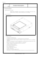
(4) Names and Functions of Each Part on the Rear Panel
Rear Panel
1. ANALOG AUDIO
Connector
:
The audio analog signal output connector.
2. CS/SL/MA Pins : By covering the jumper block, these pins are used to set the CD-R drive to
either a Master or Slave mode to work with the hard disk drive inside the
personal computer.
Default is Master.
3. IDE Connector : Using a 40-pin connector, the ATAPI terminal of the host computer is
connected to this connector.
4. DC Connector : This is the power supply terminal.
5. FACTORY USE ONLY
Pins
: These pins are used only for the test in the factory. Don’t cover the jumper
block on them.
6. DIGITAL AUDIO
Connector
: The audio digital signal output connector.
7. UDMA Pins
: UDMA mode is enabled by covering the jumper block on the 2 pins of the
UDMA jumper terminals.
Default is ON.
(Note 1) In case of using some personal computes, UDMA mode need
to be disable.
1
2
3 4
6
5
7