Multimedia Projector MODEL PLC-XU106 PLC-XU106K Owner’s Manual Network Supported Ƒ Wired LAN Refer to the Owner's Manuals below for details about network function.
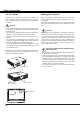
Features and Design This Multimedia Projector is designed with the most advanced technology for portability, durability, and ease of use. This projector utilizes built-in multimedia features, a palette of 16.77 million colors, and matrix liquid crystal display (LCD) technology. Ƈ Compact Design lock the operation on the top control or remote control (p.55). PIN code lock function prevents unauthorized use of the projector (pp.20, 55-56). This projector is designed compact in size and weight.
Table of Contents Features and Design . . . . . . . . . . . . . . . . . . .2 Table of Contents . . . . . . . . . . . . . . . . . . . . . .3 To the Owner. . . . . . . . . . . . . . . . . . . . . . . . . .4 Safety Instructions . . . . . . . . . . . . . . . . . . . . .5 Air Circulation Moving the Projector Installing the Projector in Proper Directions 6 6 7 Compliance . . . . . . . . . . . . . . . . . . . . . . . . . . .8 Part Names and Functions . . . . . . . . . . . . . .
To the Owner Before installing and operating this projector, read this manual thoroughly. This projector provides many convenient features and functions. Operating the projector properly enables you to manage those features and maintains it in good condition for many years to come. Improper operation may result in not only shortening the product-life, but also malfunctions, fire hazard, or other accidents.
Safety Instructions All the safety and operating instructions should be read before the product is operated. Do not install the projector near the ventilation duct of air-conditioning equipment. Read all of the instructions given here and retain them for later use. Unplug this projector from AC power supply before cleaning. Do not use liquid or aerosol cleaners. Use a damp cloth for cleaning. This projector should be operated only from the type of power source indicated on the marking label.
Safety Instructions Air Circulation Moving the Projector Openings in the cabinet are provided for ventilation. To ensure reliable operation of the product and to protect it from overheating, these openings must not be blocked or covered. When moving the projector, replace the Lens Cap and retract adjustable feet to prevent damage to the lens and cabinet. When the projector is not in use for an extended period, put it into the supplied carrying case with the lens side up.
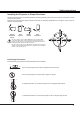
Safety Instructions Installing the Projector in Proper Directions Use the projector properly in specified positions. Improper positioning may reduce the lamp life and result in severe accident or fire hazard. This projector can project the picture upward, downward, or backward, perpendicular to the plane of the screen as shown in the figure below.
Compliance Federal Communications Commission Notice Note: This equipment has been tested and found to comply with the limits for a Class B digital device, pursuant to Part 15 of the FCC Rules. These limits are designed to provide reasonable protection against harmful interference in a residential installation. This equipment generates, uses, and can radiate radio frequency energy, and if not installed and used in accordance with the instructions, may cause harmful interference to radio communications.
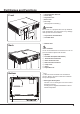
Part Names and Functions ① Infrared Remote Receiver ② Focus Ring Front ③ Projection Lens ④ Zoom Lever ⑤ Lens Cap (See page 62 for attaching.) CAUTION Do not turn on a projector with lens cap attached. High temperature from light beam may damage lens cap and result in fire hazard. ⑥ Top Controls and Indicators ⑦ Air Intake Vent ⑦ ① ② ③ ④ ⑤ ⑥⑦ ⑧ Exhaust vent Back CAUTION Hot air is exhausted from the exhaust vent. Do not put heat-sensitive objects near this side.
Part Names and Functions Rear Terminal ① ② ③ ⑩ ⑨ ① CONTROL PORT When the projector is controlled by a computer, connect to this jack with serial control cable. ② COMPUTER IN 1 / COMPONENT IN Connect output signal from a computer, RGB scart 21-pin video output or component video output to this terminal (pp.15,17). ③ MONITOR OUT This terminal can be used to output the incoming RGB signal from COMPUTER IN 1/COMPONENT IN terminal or COMPUTER IN 2 to the other monitor (pp.15,17).
Part Names and Functions Top Control ① ⑦ ② ⑧ ③ ⑨ ④ ⑩ ⑤ ⑥ ① LAMP REPLACE indicator Lights yellow when the projection lamp reaches its end of life (pp.57,63). ② ON/STAND-BY button Turn the projector on or off (pp.19-20). ③ INPUT button Select an input source (pp.29-30, 39-40). ④ KEYSTONE button Correct Standard (for Vertical/Horizontal adjustment) or Corner keystone distortion (pp.25, 48). ⑦ WARNING indicator – Lights red when the projector detects an abnormal condition.
Part Names and Functions Remote Control ① ON/STAND-BY button Turn the projector on or off. (pp.19-21) ② AUTO SET button Correct vertical keystone distortion and adjust computer display parameters such as Fine sync, Total dots, and Picture position. (pp.24, 47) ① ③ COMPUTER 1/2 buttons Select the COMPUTER 1 or COMPUTER 2 input source. (pp.29-30, 40) ② ④ VIDEO button Select the VIDEO input source. (p.39) ③ ④ ⑳ ⑲ ⑤ S-VIDEO button Select the S-VIDEO input source. (p.
Part Names and Functions Remote Control Battery Installation 1 Open the battery compartment lid. 2 Install new batteries into the compartment. 3 Replace the compartment lid. Two AAA size batteries For correct polarity (+ and –), be sure battery terminals are in contact with pins in compartment. To ensure safe operation, please observe the following precautions : Ɣ Use two (2) AAA or LR03 type alkaline batteries. Ɣ Always replace batteries in sets. Ɣ Do not use a new battery with a used battery.
Installation Positioning the Projector For projector positioning, see the figures below. The projector should be set perpendicularly to the plane of the screen. 3Note: • The brightness in the room has a great influence on picture quality. It is recommended to limit ambient lighting in order to obtain the best image. • All measurements are approximate and may vary from the actual sizes. A˖B ˙ 9 ˖1 37.4’ (11.4 m) 23.6’ (7.2 m) 300" 15.7’ (4.8 m) Max. Zoom 300" 11.8’ (3.6 m) Min. Zoom 200" 7.9’ (2.
Installation Connecting to a Computer Cables used for connection • VGA cables (Mini D-sub 15 pin) * • Audio cables (*One cable is supplied; other cables are not supplied with the projector.
Installation Connecting to Video Equipment Cables used for connection • Video and Audio cable (RCA x 3) • S-video cable • Audio cable (Cables are not supplied with the projector. ) External Audio Equipment Video and Audio Output (Video) (L) (R) Audio Input S-video Output Video and audio cable VIDEO AUDIO IN Audio cable (stereo) S-video cable AUDIO OUT (stereo) S-VIDEO IN 3Note: When the AUDIO OUT is plugged-in, the projector's builtin speaker is not available.
Installation Connecting to Component Video Equipment Cables used for connection • Audio cables • Scart-VGA cable • Component cable • Component-VGA cable (Cables are not supplied with this projector.
Installation Connecting the AC Power Cord This projector uses nominal input voltages of 100-120 V or 200-240 V AC and it automatically selects the correct input voltage. It is designed to work with single-phase power systems having a grounded neutral conductor. To reduce the risk of electrical shock, do not plug into any other type of power system. If you are not sure of the type of power being supplied, consult your authorized dealer or service station.
Basic Operation Turning On the Projector 1 Complete peripheral connections (with a computer, VCR, etc.) before turning on the projector. 2 Connect the projector’s AC power cord into an AC outlet. The POWER indicator lights red. Open the lens cap (see pages 9, 62). 3 Press the ON/STAND-BY button on the top control or on the remote control. The POWER indicator lights green and the cooling fans start to operate. The preparation display appears on the screen and the countdown starts.
Basic Operation Enter a PIN code Use the Point Ÿź buttons to enter a number. Press the Point Ź button to fix the number and move the red frame pointer to the next box. The number changes to ¼. If you fixed an incorrect number, use the Point Ż button to move the pointer to the number you want to correct, and then enter the correct number. Repeat this step to complete entering a four-digit number. After entering the four-digit number, move the pointer to Set.
Basic Operation Turning Off the Projector 1 Press the ON/STAND-BY button on the top control or on the remote control, and Power off? appears on the screen. 2 Press the ON/STAND-BY button again to turn off the projector. The POWER indicator starts to blink red, and the cooling fans keep running. (You can select the level of fans’ quietness and speed. See “Fan” on page 57.) At this time, you can unplug the AC power cord even if the fans are still running. 3 Power off? disappears after 4 seconds.
Basic Operation How to Operate the On-Screen Menu The projector can be adjusted or set via the On-Screen Menu. The menus have a hierarchical structure, with a main menu that is divided into submenus, which are further divided into other submenus. For each adjustment and setting procedure, refer to respective sections in this manual. 1 Press the MENU button on the top control or the remote control to display the On-Screen Menu. 2 Use the Point Ÿź buttons to highlight and select a main menu item.
Basic Operation Menu Bar For detailed functions of each menu, see “Menu Tree” on pages 69-70. Main Menu Sub-Menu ① ② ③ ④ ⑤ ⑥ ⑦ ⑧ ⑨ ⑩ ① Input Used to select an input source from Computer 1, Computer 2, Video or S-video. (pp.29-30,39-40) ② PC adjust Select Auto PC adj., Fine sync, Total dots, Horizontal, Vertical, Clamp, Display area H and Display area V to adjust the parameters to match with the PC input signal format. (pp.
Basic Operation Zoom and Focus Adjustment Rotate the Zoom Lever to zoom in and out. Rotate the Focus Ring to adjust the focus of the image. Zoom Lever Focus Ring Auto Setup Function Auto setup function is provided to automatically execute the setting of Auto setup (includes Input search, Auto PC adj. and Auto keystone functions) in the Setting Menu by just pressing the AUTO SETUP button on the top control or the AUTO SET button on the remote control.
Basic Operation Keystone Correction If a projected picture still has keystone distortion after pressing the AUTO SETUP button on the top control or the AUTO SET button on the remote control, correct the image manually as follows: Press the KEYSTONE button on the top control or on the remote control to switch the Standard (for Vertical/ Horizontal) /Corner adjustment. The Standard or Corner adjustment dialog box appears. Use the Point ŸźŻŹ buttons to correct the Standard or Corner distortion.
Basic Operation Sound Adjustment Direct Operation Top Control 92/80( EXWWRQV Volume Press the VOLUME+/– buttons on the top control or on the remote control to adjust the volume. The volume dialog box appears on the screen for a few seconds. Mute Remote Control Press the MUTE button on the remote control to select On to temporarily turn off the sound. To turn the sound back on, press the MUTE button again to select Off or press the VOLUME +/– buttons.
Basic Operation Remote Control Operation Using the remote control for some frequently used operations is advisable. Just pressing one of the buttons enables you to make the desired operation quickly without calling up the On-Screen Menu. COMPUTER 1/2, VIDEO, S-VIDEO and COMPONENT buttons Press the COMPUTER 1/2, VIDEO, S-VIDEO and COMPONENT buttons on the remote control to select the input source. See pages 29-30, 39-40 for details.
Basic Operation NO SHOW button Press the NO SHOW button on the remote control to black out the image. To restore to normal, press the NO SHOW button again or press any other button. The screen changes each time you press the NO SHOW button as follows. EODFN RXWĺ QRUPDO ĺ EODFN RXW ĺ QRUPDO ĺ ••••• No show disappears after 4 seconds. P-TIMER button Press the P-TIMER button on the remote control. The P-Timer display 00:00 appears on the screen and the countdown starts (00:00–59:59).
Computer Input Input Source Selection (Computer 1: RGB) Direct Operation Choose Computer 1(RGB) by pressing the INPUT button on the top control or press the COMPUTER 1 button on the remote control. Before using INPUT button, correct input source should be selected through Menu operation as described below.
Computer Input Input Source Selection (Computer 2: RGB) Direct Operation Choose Computer 2 (RGB) by pressing the INPUT button on the top control or press the COMPUTER 2 button on the remote control.
Computer Input Computer System Selection This projector automatically tunes to various types of computers with its Multi-scan system and Auto PC adjustment. If a computer is selected as a signal source, this projector automatically detects the signal format and tunes to project a proper image without any additional settings. (Signal formats provided in this projector are shown on pages 72.
Computer Input Auto PC adjustment Auto PC adjustment function is provided to automatically adjust Fine sync, Total dots, Horizontal , Vertical , Clamp, Display area H and Display area V positions to conform to your computer. Menu Operation PC adjust Menu Auto PC adj. 1 Press the MENU button to display the On-Screen Menu. Use the Point Ÿź buttons to select PC adjust and then press the Point Ź or the SELECT button. 2 Use the Point Ÿź buttons to select Auto PC adj. and then press the SELECT button.
Computer Input Manual PC adjustment Some computers employ special signal formats which may not be tuned by Multi-scan system of this projector. Manual PC adjustment enables you to precisely adjust several parameters to match those signal formats. The projector has five independent memory areas to store those parameters manually adjusted. It allows you to recall the setting for a specific computer. 1 Press the MENU button to display the On-Screen Menu.
Computer Input Mode free Menu Reset To reset the adjusted data, select Reset and press the SELECT button. A confirmation box appears and then select Yes. All adjustments will return to their previous figures. Mode free To clear the stored data, select Mode free and then press the Point Ź or the SELECT button. Move the highlight to the Mode that you want to clear and then press the SELECT button. This Mode has stored parameters.
Computer Input Image Mode Selection Direct Operation Remote Control Select the desired image mode among Dynamic, Standard, Real, Blackboard (Green), Colorboard, Image 1, Image 2, Image 3, and Image 4 by pressing the IMAGE button on the remote control. IMAGE button Dynamic Standard Real Blackboard(Green) IMAGE button Colorboard Image 1 Image 2 Menu Operation 1 2 Image 3 Press the MENU button to display the On-Screen Menu.
Computer Input Image Adjustment 1 Press the MENU button to display the On-Screen Menu. Use the Point Ÿź buttons to select Image adjust and then press the Point Ź or the SELECT Image adjust Menu button. 2 Use the Point Ÿź buttons select the desired item and then press the SELECT button to display the adjustment dialog box. Use the Point ŻŹ buttons to adjust the setting value. Contrast Press the Point Ż button to decrease the contrast; press the Point Ź button to increase the contrast (from 0 to 63).
Computer Input Store To store the adjusted data, select Store and press the Point Ź or the SELECT button. Use the Point Ÿź buttons to select one from Image 1 to 4 and press the SELECT button. A confirmation box appears and then select Yes. Stored data can be called up by selecting an ,PDJH ± in the Image Mode Selection on page 35. Screen Size Adjustment This projector has the picture screen resize function, which enables you to customize the image size.
Computer Input Custom Adjust the screen scale and position manually with this function. Press the Point Ź button at Custom and the Custom adjustment menu is displayed on the screen, you can use the Point Ÿź EXWWRQV WR FKRRVH WKH LWHP \RX ZDQW WR adjust. Scale H/V .......... Adjust the Horizontal/Vertical screen scale. H&V ................... When set to On, the aspect ratio is fixed. The Scale V appears dimmed and becomes unavailable.
Video Input Input Source Selection (Video, S-video) Direct Operation Top Control Choose Video or S-video by pressing the INPUT button on the top control, or the VIDEO button or the S-VIDEO button on the remote control. INPUT button Computer 1(RGB) / (Component) / (Scart) Computer 2(RGB) Video S-video Remote Control VIDEO button Video S-video button S-video Menu Operation 1 Press the MENU button to display the On-Screen Menu.
Video Input Input Source Selection (Component, RGB Scart 21-pin) Direct Operation Choose Computer 1(Component) or Computer 1(Scart) by pressing the INPUT button on the top control or pressing the COMPUTER 1 or the COMPONENT button on the remote control. Before using INPUT button, correct input source should be selected through Menu operation as described below.
Video Input Video System Selection 1 Press the MENU button to display the On-Screen Menu. Use the Point Ÿź buttons to select Input and then press the Point Ź or the SELECT button. 2 Use the Point Ÿź buttons to select Video or S-video or Computer 1(Component) and then press the SELECT button. 3 Use the Point Ÿź buttons to select System and then press the Point Ź or the SELECT button. Use the Point Ÿź buttons to select the desired system and then press the SELECT button.
Video Input Image Mode Selection Direct Operation Remote Control IMAGE button Dynamic Select the desired image mode from among Dynamic, Standard, Cinema, Blackboard (Green), Colorboard, Image 1, Image 2, Image 3, and Image 4 by pressing the IMAGE button on the remote control. Standard Cinema Blackboard (Green) IMAGE button Menu Operation 1 2 Colorboard Press the MENU button to display the On-Screen Menu. Use the Point Ÿź buttons to select Image select and then press the Point Ź or the SELECT button.
Video Input Image Adjustment 1 Press the MENU button to display the On-Screen Menu. Use the Point Ÿź buttons to select the Image adjust and then press the Point Ź or the SELECT button. 2 Use the Point Ÿź buttons select the desired item and then press the SELECT button to display the adjustment dialog box. Use the Point ŻŹ buttons to adjust the setting value. Image adjust Menu Contrast Press the Point Ż button to decrease the contrast; press the Point Ź button to increase the contrast (from 0 to 63).
Video Input Sharpness Press the Point Ż button to decrease the sharpness of the image; press the Point Ź button to increase the sharpness of the image (from 0 to 15). Gamma Use the Point ŻŹ buttons to adjust the gamma value to obtain a better balance of contrast (from 0 to 15). Noise reduction Noise interference on the screen can be reduced. Select one of the following options to get smoother images. Off ......... Disabled. L 1 ......... Lower reduction L 2 .........
Video Input Screen Size Adjustment This projector has the picture screen resize function, which enables you to customize the image size. 1 Press the MENU button to display the On-Screen Menu. Use the Point Ÿź buttons to select Screen and then press the Point Ź or the SELECT button. 2 Use the Point Ÿź buttons select the desired item and then press the SELECT button. Screen Menu Normal Provide the image at the 4:3 normal video aspect ratio. Wide Provide the image at the 16:9 wide screen ratio.
Setting Setting This projector has a Setting Menu that allows you to set up the other various functions described below. Setting Menu Language 1 2 3 English Menu position Press the MENU button to display the On-Screen Menu. Press the Point Ÿź buttons to select the Setting and press the Point Ź or the SELECT button to access the submenu items.
Setting Auto setup This function enables Input search, Auto Keystone correction and Auto PC adjustment by pressing the AUTO SETUP button on the top control or the AUTO SET button on the remote control. Settings for those functions can be altered as follows: Input search This function detects the input signal automatically. When a signal is found, the search will stop. Use the Point Ÿź buttons to select one of the following options. Off ......... Input search will not work. On 1.......
Setting Keystone This function is used to adjust keystone distortion of the projected image. Use the Point Ÿź buttons to choose the item you want to adjust. Standard Adjust the Horizontal/Vertical keystone distortion of the projected image. Corner correction Adjust the corner distortion of the projected image. Corner pattern Choose a Corner pattern mode among Red, White, Blue, and Off. Store Store ..... Keep the keystone correction even when the AC power cord is unplugged. Reset.....
Setting Logo (Logo and Logo PIN code lock settings) This function allows you to customize the screen logo with Logo select, Capture, Logo PIN code lock and Logo PIN code change functions. Logo select Language Auto setup Keystone 3Note: When On is selected in the Logo PIN code lock function, Logo select and Capture functions cannot be selected. English Menu position Store Background Blue Display On Logo more...
Setting Capture This function enables you to capture an image being projected to use it for a starting-up display or interval of presentations. Capture Select Capture and press the SELECT button. A confirmation box appears and select Yes to capture the projected image. After capturing the projected image, go to the Logo select function and set it to User. Then the captured image will be displayed the next time you turn on the projector.
Setting Enter a Logo PIN code Use the Point Ÿź buttons to enter a number. Press the Point Ź button to fix the number and move the red frame pointer to the next box. The number changes to ¼. If you fixed an incorrect number, use the Point Ż button to move the pointer to the number you want to correct, and then enter the correct number. Enter a Logo PIN code Repeat this step to complete entering a four-digit number. After entering the four-digit number, move the pointer to Set.
Setting Ceiling Ceiling When this function is set to On, the picture will be top/ bottom and left/right reversed. This function is used to project the image from a ceiling-mounted projector. Rear When this function is set to On, the picture will be left/right reversed. This function is used to project the image from rear of the screen.
Setting On start When this function is set to On, the projector will be automatically turned on just by connecting the AC power cord to a wall outlet. 3Note: Be sure to turn off the projector properly (see “Turning Off the Projector” on page 21). If the projector is turned off in the incorrect sequence, the On start function does not work properly.
Setting Lamp control This function allows you to change brightness of the screen. High .......... Brighter than the Normal mode. Normal ...... Normal brightness Eco............ Lower brightness reduces the lamp power consumption and extends the lamp life. Remote control This projector provides two different remote control codes: the factory-set initial code (Code 1) and the secondary code (Code 2).
Setting Security (Key lock and PIN code lock) Key lock This function allows you to use the Key lock and PIN code lock function to set the security for the projector operation. Key lock This function locks the top control and remote control buttons to prevent operation by unauthorized persons. Select Key lock and then press the SELECT button, and select the desired item by pressing the Point Ÿź buttons. ..... Unlocked. ..... Lock the operation of the top control. To unlock, use the remote control. .....
Setting Enter a PIN code Use the Point Ÿź buttons to enter a number. Press the Point Ź button to fix the number and move the red frame pointer to the next box. The number changes to ¼. If you fixed an incorrect number, use the Point Ż button to move the pointer to the number you want to correct, and then enter the correct number. Enter a PIN code Repeat this step to complete entering a four-digit number. After entering the four-digit number, move the pointer to “Set.
Setting Fan This function provides the following options in the cooling fans’ operation when the projector is turned off (p.21). L 1 ..... Normal operation L 2 ..... Slower and lower-sound than the normal operation (L 1), but it takes more time to cool the projector down. Fan control Choose the running speed of cooling fans from the following options according to the ground elevation under which you use the projector. Off.......Normal speed.
Setting Filter counter This function is used to set a frequency for the filter cleaning. Filter counter When the projector reached a specified time between cleanings, a Filter warning icon appears on the screen, notifying the cleaning is necessary. After cleaning the filter, be sure to select RESET and set the timer. The Filter warning icon will not turn off until the filter counter is reset. For details about resetting the timer, refer to “Resetting the Filter Counter” on page 61. Fig.
Information Input Source Information Display The Information Menu is used for checking the status of the image signal being projected and the operation of the projector. Direct Operation Press the INFO. button on the remote control to display the Information Menu. Remote Control INFO. button Menu Operation Press the Point Ÿź buttons to select the Information. The Information Menu is displayed. See below for displayed information. Input The selected input source is displayed.
Maintenance and Cleaning WARNING indicator The WARNING indicator shows the state of the function which protects the projector. Check the state of the WARNING indicator and the POWER indicator to take proper maintenance. The projector is shut down and the WARNING indicator is blinking red. Top Control WARNING blinking red When the temperature inside the projector reaches a certain level, the projector will be automatically shut down to protect the inside of the projector.
Maintenance and Cleaning Cleaning the Filters Filters prevents dust from accumulating on the optical elements inside the projector. Should the filters become clogged with dust particles, it will reduce cooling fans’ effectiveness and may result in internal heat buildup and adversely affect the life of the projector. If a “Filter warning” icon appears on the screen, clean the filters immediately. Clean the filter by following the steps below.
Maintenance and Cleaning Attaching the Lens Cap Lens Cap When moving this projector or while not using it over an extended period of time, replace the lens cap. Attach the lens cap according to the following procedures. 1 Pass the string through a hole of the lens cap. 2 Turn over the projector and remove the screw with a screwdriver. 3 Attach the string with lens cap to a hole at the bottom of the projector and secure it with a screw.
Maintenance and Cleaning Lamp Replacement When the projection lamp of the projector reaches its end of life, the Lamp replacement icon appears on the screen and LAMP REPLACE indicator lights yellow. Replace the lamp with a new one promptly. The timing when the LAMP REPLACE indicator should light is depending on the lamp mode.
Maintenance and Cleaning Resetting the Lamp Counter Be sure to reset the Lamp counter after the lamp is replaced. When the Lamp counter is reset, the LAMP REPLACE indicator stops lighting and the Lamp replacement icon disappears. 1 Press the MENU button to display the On-Screen Menu. Use the Point Ÿź buttons to select Setting and then press the Point Ź RU WKH 6(/(&7 button. 2 Use the Point Ÿź buttons to select Lamp counter and then press the SELECT button.
Appendix Troubleshooting Before calling your dealer or service center for assistance, check the items below once again. –Make sure you have properly connected the projector to peripheral equipment as described on pages 15-17. –Make sure all equipment is connected to AC outlet and the power is turned on. –When the projector does not project an image from the connected computer, restart the computer. Problem: – Solutions No power – Plug the power cord of the projector into the AC outlet.
Appendix No image – Check the connection between your computer or video equipment and the projector. See pages 15-17. – See if the input signal is correctly output from your computer. Some laptop computers may need to change the setting for monitor output when connecting to a projector. See your computer’s instruction manual for the setting. – It takes about 30 seconds to display an image after turning on the projector. See page 19.
Appendix The image is distorted or runs off. – Check PC adjustment Menu or Screen and adjust them. See pages 33-34, 37-38. PIN code dialog box appears at start-up. – PIN code lock is being set. Enter a PIN code (the “1234” or numbers you have set). See pages 20, 55-56. The Remote Control does not work. – Check the batteries. – Make sure no obstruction is between the projector and remote control. – Make sure you are not too far from the projector when using the remote control.
Appendix WARNING : High voltages are used to operate this projector. Do not attempt to open the cabinet. If problems still persist after following all operating instructions, contact the dealer where you purchased the projector or the service center. Specify the model number and explain about the problem. We will advise you how to obtain service. The CE Mark is a Directive conformity mark of the European Community (EC). Pixelworks ICs used.
Appendix Menu Tree Computer Input/Video Input Input Input RGB Computer 1 Component RGB (Scart) RGB Computer 2 Video S-video Sound Volume Mute Sound 0-63 On / Off Computer Input Image select Dynamic Standard Real Blackboard (Green) Colorboard Red / Blue / Yellow / Green Image 1 Image 2 Image 3 Image 4 Image adjust Contrast Brightness Color temp. SVGA 1 Mode 1 Mode 2 ---- System (1) * Systems displayed in the System Menu vary depending on an input signal. PC adjust Auto PC adj.
Appendix Video Input Setting Image adjust Language Auto setup Off / On 1 / On 2 Standard Keystone Corner correction Corner pattern Off / Red / White / Blue Store Store Reset Background Blue / Black / User Display On / Countdown off / Off Logo Logo select Contrast Brightness Color Tint Color temp.
Appendix Indicators and Projector Condition Check the indicators for projector condition. Indicators POWER WARNING red/green red Projector Condition LAMP REPLACE yellow The projector is off. (The AC power cord is unplugged.) ¼ The projector is in stand-by mode. Press the ON/STAND-BY button to turn on the projector. ¼ The projector is operating normally. ¼ The projector is preparing for stand-by or the projection lamp is being cooled down.
Appendix Compatible Computer Specifications Basically this projector can accept the signal from all computers with the V-, H-Frequency mentioned below and less than 140 MHz of Dot Clock. When selecting these modes, PC adjustment can be limited.
Appendix Technical Specifications Mechanical Information Projector Type Dimensions (W x H x D) Net Weight )HHW $GMXVWPHQW Multi-media Projector 13.15" x 3.07" x 10.14" ( 334 mm x 78 mm x 257.5mm ) (Not including protrusions) 7.72 lbs (3.5 kg) Û WR Û Panel Resolution LCD Panel System Panel Resolution Number of Pixels 0.8" TFT Active Matrix type, 3 panels 1,024 x 768 dots 2,359,296 (1,024 x 768 x 3 panels) Signal Compatibility Color System PAL, SECAM, NTSC, NTSC4.
Appendix Accessories Owner’s Manual (CD-ROM) Quick Reference Guide & Safety Manual AC Power Cord Remote Control and Batteries VGA Cable Lens Cap with String PIN Code Label Network Application (CD-ROM) Soft Carrying Case Ɣ Ɣ The specifications are subject to change without notice. LCD panels are manufactured to the highest possible standards. Even though 99.99% of the pixels are effective, a tiny fraction of the pixels (0.01% or less) may be ineffective by the characteristics of the LCD panels.
Appendix PJ Link Notice This projector is compliant with PJLink Standard Class 1 of JBMIA (Japan Business Machine and Information System Industries Association). This projector supports all commands defined by PJLink Class 1 and is verified conformance with PJLink Standard Class 1. For PJ Link password, see the owner’s manual of “Network Set-up and Operation.
Appendix Configurations of Terminals COMPUTER IN 1 /COMPONENT IN /COMPUTER IN 2/MONITOR OUT (ANALOG) Terminal: Analog RGB (Mini D-sub 15 pin) 4 5 10 15 9 14 2 3 8 13 7 12 1 2 3 4 5 6 7 8 1 6 11 Red (R/Cr) Input/Output Green (G/Y) Input/Output Blue (B/Cb) Input/Output ----Ground (Horiz.sync.
Appendix PIN Code Number Memo Write down the PIN code number in the column below and keep it with this manual securely. If you forgot or lost the number and unable to operate the projector, contact the service station. PIN Code Lock No. Factory default set No: 1 2 3 4* Logo PIN Code Lock No. Factory default set No: 4 3 2 1* *Should the four-digit number be changed, the factory set number will be invalid. While the projector is locked with the PIN code.
Appendix Dimensions Unit: inch(mm) Screw Holes for Ceiling Mount Screw: M4 Depth: 0.472(12.0) 13.15(334) 3.1(78) 3.6(91.3) 2.0(51.3) 3.17(80.5) 5.5(140.0) 5.1(129.0) 78 5.2(132.0) 2.8(70.5) 10.2 (257.5) 5.1(129.0) 4.4(112.
Appendix 79
KB8AC SANYO Electric Co., Ltd.