92-131 S/M (Basic) 2/21/01 4:49 PM Page A SERVICE MANUAL (Basic Information) CM3212 / KMS0712 (✕ 2)+KMS1812 SPLIT SYSTEM AIR CONDITIONER Indoor Unit Outdoor Unit CM3212 KMS0712 KMS1812 8526481017300 REFERENCE NO.
92-131 S/M (Basic) 2/21/01 4:49 PM Page B
92-131 S/M (Basic) 2/21/01 4:49 PM Page ii SERVICE MANUAL CM3212 / KMS0712(×2)+KMS1812 (Basic Information) ii WM – 700699
92-131 S/M (Basic) 2/21/01 4:49 PM Page iii • Connect all wiring tightly. Loose wiring may cause overheating at connection points and a possible fire hazard. IMPORTANT! Please Read Before Starting When Transporting This air conditioning system meets strict safety and operating standards. As the installer or service person, it is an important part of your job to install or service the system so it operates safely and efficiently. Be careful when picking up and moving the indoor and outdoor units.
92-131 S/M (Basic) 2/21/01 4:49 PM Page iv Table of Contents Page 1. OPERATING RANGE............................................................................................................................... 1 2. SPECIFICATIONS .................................................................................................................................... Unit Specifications ..........................................................................................................................
92-131 S/M (Basic) 2/21/01 4:49 PM Page 1 1. OPERATING RANGE CM3212 / KMS0712(×2)+KMS1812 Temperature Maximum Minimum Indoor Air Intake Temp. 95°F DB / 71°F WB 67°F DB / 57°F WB Outdoor Air Intake Temp.
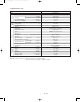
92-131 S/M p.2 Table 2/21/01 4:55 PM Page 2 2. SPECIFICATIONS Unit Specifications Dimensions & Weight Features Electrical Rating Performance Model No. Outdoor unit Applicable indoor unit No. of indoor units Capacity BTU/h kW Hz V V A W % A BTU/Wh Phase, Frequency Voltage rating Available voltage range Running amperes Power input Power factor Starting amperes S. E. E. R. Fan speeds Compressor … number Refrigerant amount charged at shipment lbs.
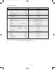
92-131 S/M (Basic) 2/21/01 4:49 PM Page 3 Applicable Indoor Unit Dimensions & Weight Features Electrical Rating Performance Model No. Type Capacity KMS0712 Wall-mounted Cooling 7,000 / 7,700 2.05 / 2.05 220 / 210 2.2 / 2.1 Single, 60 230 / 208 187 to 253 Microprocessor Wireless remote control unit IC thermostat ON/OFF 24-hours & Program 3 Manual / Manual Washable, easy access 45 / 35 / 30 Flare type 1/4 (6.35) 3/8 (9.
2-131 S/M (Basic) 2/21/01 4:49 PM Page 4 Applicable Indoor Unit Dimensions & Weight Features Electrical Rating Performance Model No. Type Capacity KMS1812 Wall-mounted Cooling 18,000 / 17,600 5.27 / 5.16 440 / 420 5.3 / 5.2 Single, 60 230 / 208 187 to 253 Microprocessor Wireless remote control unit IC thermostat ON/OFF 24-hours & Program 3 Manual / Manual Washable, easy access 47 / 44 / 40 Flare type 1/4 (6.35) 1/2 (12.
92-131 S/M (Basic) 2/21/01 4:49 PM Page 5 3. DIMENSIONAL DATA Outdoor Unit: CM3212 Air intake 25-1/16 26-3/8 21/32 Air intake 21/32 Air intake 21/32 25-1/16 26-3/8 4 × 15/32 dia.
92-131 S/M (Basic) 2/21/01 4:49 PM Page 6 Indoor Unit: KMS0712 Rear panel (center point of gravity) 7-11/64 7-3/32 17-23/32 6-23/32 3-3/4 5-1/2 Center of tubing hole (for right rear) 1-49/64 6-7/64 2-13/64 1-49/64 1-3/8 15/32 Wireless remote control unit 1-49/64 13-19/32 1-5/8 31-1/2 Drain hose O.D. 23/32 O.D. 1/4" narrow tubing O.D.
92-131 S/M (Basic) 2/21/01 4:49 PM Page 7 4. COOLING CAPACITY 230V CM3622 / KMS0712×1 Rating Capacity: 7,000 BTU/H Evaporator Ent. Temp. °F/(°C) WB DB 59 (15.0) 72 (22.2) 76 (24.4) 80 (26.7) 84 (28.9) 88 (31.1) 63 (17.2) 72 (22.2) 76 (24.4) 80 (26.7) 84 (28.9) 88 (31.1) 67 (19.4) 72 (22.2) 76 (24.4) 80 (26.7) 84 (28.9) 88 (31.1) 71 (21.7) 72 (22.2) 76 (24.4) 80 (26.7) 84 (28.9) 88 (31.1) 75 (23.9) 76 (24.4) 80 (26.7) 84 (28.9) 88 (31.
92-131 S/M (Basic) 2/21/01 4:49 PM Page 8 208V CM3622 / KMS0712×1 Rating Capacity: 7,000 BTU/H Evaporator Ent. Temp. °F/(°C) WB DB 59 (15.0) 72 (22.2) 76 (24.4) 80 (26.7) 84 (28.9) 88 (31.1) 63 (17.2) 72 (22.2) 76 (24.4) 80 (26.7) 84 (28.9) 88 (31.1) 67 (19.4) 72 (22.2) 76 (24.4) 80 (26.7) 84 (28.9) 88 (31.1) 71 (21.7) 72 (22.2) 76 (24.4) 80 (26.7) 84 (28.9) 88 (31.1) 75 (23.9) 76 (24.4) 80 (26.7) 84 (28.9) 88 (31.
92-131 S/M (Basic) 2/21/01 4:49 PM Page 9 230V CM3622 / KMS1812 Rating Capacity: 18,000 BTU/H Evaporator Ent. Temp. °F/(°C) WB DB 59 (15.0) 72 (22.2) 76 (24.4) 80 (26.7) 84 (28.9) 88 (31.1) 63 (17.2) 72 (22.2) 76 (24.4) 80 (26.7) 84 (28.9) 88 (31.1) 67 (19.4) 72 (22.2) 76 (24.4) 80 (26.7) 84 (28.9) 88 (31.1) 71 (21.7) 72 (22.2) 76 (24.4) 80 (26.7) 84 (28.9) 88 (31.1) 75 (23.9) 76 (24.4) 80 (26.7) 84 (28.9) 88 (31.
92-131 S/M (Basic) 2/21/01 4:49 PM Page 10 208V CM3622 / KMS1812 Rating Capacity: 17,600 BTU/H Evaporator Ent. Temp. °F/(°C) WB DB 59 (15.0) 72 (22.2) 76 (24.4) 80 (26.7) 84 (28.9) 88 (31.1) 63 (17.2) 72 (22.2) 76 (24.4) 80 (26.7) 84 (28.9) 88 (31.1) 67 (19.4) 72 (22.2) 76 (24.4) 80 (26.7) 84 (28.9) 88 (31.1) 71 (21.7) 72 (22.2) 76 (24.4) 80 (26.7) 84 (28.9) 88 (31.1) 75 (23.9) 76 (24.4) 80 (26.7) 84 (28.9) 88 (31.
92-131 S/M (Basic) 2/21/01 4:49 PM Page 11 5. REFRIGERANT FLOW DIAGRAM Narrow tube O.D. 1/4" (6.35 mm) O.D. 1/4" (6.35 mm) O.D. 1/4" (6.35 mm) Narrow tube service valve A Capillary tube OUTDOOR UNIT Drier B C Heat exchanger Heat exchanger INDOOR UNIT UNIT A Check port A Check port B INDOOR UNIT UNIT B O.D. 1/2" (12.7 mm) B Accumulator C INDOOR UNIT UNIT C Heat exchanger Accumulator 11 WM – 700699 Compressor A O.D. 3/8" (9.
92-131 S/M (Basic) 2/21/01 4:49 PM Page 12 6. ELECTRICAL DATA ● Electrical Characteristics CM3212 / KMS0712×1 Performance at 230/208V – 1ø – 60Hz Rating Conditions Locked-Rotor Amperes A W A Indoor Unit Fan Motor 0.15 / 0.14 34 / 28 0.19 / 0.18 Outdoor Unit Fan Motor Compressor 0.62 / 0.56 2.53 / 2.80 140 / 126 576 / 566 1.95 / 1.77 22 Complete Unit 3.3 / 3.
92-131 S/M (Basic) 2/21/01 4:49 PM Page 13 CM3212 / KMS0712+KMS1812 Performance at 230/208V – 1ø – 60Hz Rating Conditions Locked-Rotor Amperes Outdoor Unit Fan Motor Compressor 1.45 / 1.42 9.80 / 10.64 330 / 290 2,246 / 2,202 1.95 / 1.77 22 + 54 Indoor Units A W A 0.55 / 0.54 124 / 108 0.19 + 0.45 / 0.18 + 0.40 Complete Unit 11.8 / 12.
Page 14 ● Electrical Wiring Diagram WARNING: To avoid electrical shock hazard, be sure to disconnect power before checking, servicing and/or cleaning any electrical parts.
2/21/01 4:49 PM Page 15 TO OUTDOOR UNIT Indoor Unit: KMS0712 WARNING: To avoid electrical shock hazard, be sure to disconnect power before checking, servicing and/or cleaning any electrical parts.
2/21/01 4:49 PM Page 16 WARNING: WHT 1 BLU 1 2 1 2 1 2 1 2 1 2 1 2 2P CM 2P TH1 2P TH2 BLU BRN BRN BRN 1 2 3 1 2 3 3P Supply 1 1 2P 2 2 SEC CONTROLLER 1 1 2P 2 2 PRY 2P LM 5P FM 1 2 3 4 5 1 2 3 4 5 BRN PNK Capacitor Switch assy 1 2 1 2 GRY GRY P WHT WHT GRY VLT WHT YEL Transformer BLK BLK 2 Thermistor RED BLK BLK Power relay 3 Thermistor Terminal plate Connector 1 1 2 2 BRN S To avoid electrical shock hazard, be sure to disconnect power before checking, servicing and/or c
92-131 S/M (Basic) 2/21/01 4:49 PM Page 17 For parts or service contact SFS Corporation: 1200 West Artesia Blvd., Compton, California 90220 CORPORATION In Canada SANYO Canada Inc.: Toronto, Ont. M4H 1M6 H406/12M 1991/Nov./12M Printed in in U.S.A. U.S.A.