TECHNICAL & SERVICE MANUAL OUTDOOR UNIT : SAP-CMRV1426EH SAP-CMRV1926EH SAP-CMRV1936EH SAP-CMRV2446EH SAP-CMRV3146EH FILE NO. Destination: Europe DC INVERTER MULTI-SYSTEM AIR CONDITIONER Capacity Product Code No. SAP-CMRV1926EH-F 1 852 355 44 SAP-CMRV1426EH-F 5.6kW SAP-CMRV1936EH-F 5.6kW 6.8kW 8.0kW SAP-CMRV1426EH Outdoor Model No. 4.
Important! Please Read Before Starting When Transporting Be careful when picking up and moving the indoor and outdoor units. Get a partner to help, and bend your knees when lifting to reduce strain on your back. Sharp edges or thin aluminum fins on the air conditioner can cut your fingers. This air conditioning system meets strict safety and operating standards. As the installer or service person, it is an important part of your job to install or service the system so it operates safely and efficiently.
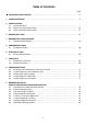
Table of Contents Page APPLICABLE INDOOR UNITS .................................................................................................... 5 1. OPERATING RANGE ................................................................................................................... 6 2. SPECIFICATIONS 2-1. Unit Specifications ............................................................................................................. 2-2. Major Component Specifications ................................
Page APPENDIX A INSTALLATION INSTRUCTIONS ............................................................................. A-1 (SAP-CMRV1426EH) APPENDIX B INSTALLATION INSTRUCTIONS ............................................................................. A-2 SAP-CMRV1926EH, SAP-CMRV1936EH SAP-CMRV2446EH, SAP-CMRV3146EH ( ) APPENDIX C UNIT COMBINATION TABLES .................................................................................
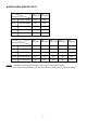
APPLICABLE INDOOR UNITS Indoor Unit Multi-Outdoor Unit SAPKRV126EHDS 2-Room SAP-CMRV1426EH YES YES 2-Room SAP-CMRV1926EH YES YES 3-Room SAP-CMRV1936EH YES YES 4-Room SAP-CMRV2446EH YES YES 4-Room SAP-CMRV3146EH YES YES SAPKMRV76EH SAPKMRV96EH SAPKMRV126EH SAPKRV186EH SAPKRV246EH Indoor Unit Multi-Outdoor Unit NOTE SAPKRV96EHDSA 2-Room SAP-CMRV1426EH YES YES YES NO NO 2-Room SAP-CMRV1926EH YES YES YES YES NO 3-Room SAP-CMRV1936EH YES YES YES YES NO 4-Room S
1. OPERATING RANGE Outdoor Unit : SAP-CMRV1426EH, SAP-CMRV1926EH, SAP-CMRV1936EH SAP-CMRV2446EH, SAP-CMRV3146EH Indoor Unit : SAP-KRV96EHDSA, SAP-KRV126EHDS SAP-KMRV76EH, SAP-KMRV96EH, SAP-KMRV126EH SAP-KRV186EH, SAP-KRV246EH Temperature Cooling Heating Maximum Minimum Maximum Minimum Indoor Air Intake Temp. 32 °C D.B. / 23 °C W.B. 19 °C D.B. / 14 °C W.B. 27 °C D.B. 16 °C D.B. Outdoor Air Intake Temp. 43 °C D.B. -5 °C W.B. 24 °C D.B. / 18 °C W.B. _ D.B. / -15 °C W.B. (*1) 0 °C D.B.
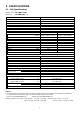
2. SPECIFICATIONS 2-1. Unit Specifications Outdoor Unit Indoor Unit SAP-CMRV1426EH SAP-KMRV96EH × 2 Type 2-Room Multi Outdoor Unit Number of Connectable Indoor Units 2 Number of Operatable Indoor Units 2 Max. Capacity of Operating Indoor Units kW 6.15 Power Source 220 to 240V Single-Phase 50Hz Voltage Rating 230V Performance Capacity Air Circulation (High) Electrical Rating Available Voltage Range Running Amperes Power Input Power Factor E.E.R. C.O.P.
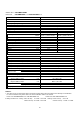
Outdoor Unit Indoor Unit SAP-CMRV1926EH SAP-KMRV96EH × 1 + SAP-KRV186EH × 1 Type 2-Room Multi Outdoor Unit Number of Connectable Indoor Units 2 Number of Operatable Indoor Units 2 Max. Capacity of Operating Indoor Units kW 8.65 Power Source 220 to 240V Single-Phase 50Hz Voltage Rating 230V Performance Capacity Air Circulation (High) Electrical Rating Available Voltage Range Running Amperes Power Input Power Factor E.E.R. C.O.P.
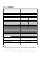
Outdoor Unit Indoor Unit SAP-CMRV1936EH SAP-KMRV96EH × 3 Type 3-Room Multi Outdoor Unit Number of Connectable Indoor Units 3 Number of Operatable Indoor Units 3 Max. Capacity of Operating Indoor Units kW 10.5 Power Source 220 to 240V Single-Phase 50Hz Voltage Rating 230V Performance Capacity Air Circulation (High) Electrical Rating Available Voltage Range Running Amperes Power Input Power Factor E.E.R. C.O.P.
Outdoor Unit Indoor Unit SAP-CMRV2446EH SAP-KMRV96EH × 4 Type 4-Room Multi Outdoor Unit Number of Connectable Indoor Units 4 Number of Operatable Indoor Units 4 Max. Capacity of Operating Indoor Units kW 13.1 Power Source 220 to 240V Single-Phase 50Hz Voltage Rating 230V Performance Capacity Air Circulation (High) Electrical Rating Available Voltage Range Running Amperes Power Input Power Factor E.E.R. C.O.P.
Outdoor Unit Indoor Unit SAP-CMRV3146EH SAP-KMRV96EH × 4 Type 4-Room Multi Outdoor Unit Number of Connectable Indoor Units 4 Number of Operatable Indoor Units 4 Max. Capacity of Operating Indoor Units kW 14.7 Power Source 220 to 240V Single-Phase 50Hz Voltage Rating 230V Performance Capacity Air Circulation (High) Electrical Rating Available Voltage Range Running Amperes Power Input Power Factor E.E.R. C.O.P.
2-2. Major Component Specifications 2-2-1. Outdoor Unit Outdoor Unit SAP-CMRV1426EH Control PCB Part No. Controls Control Circuit Fuse CB-CMRV1426EH Microprocessor 250V 25A Compressor Type Compressor Model / Nominal Output Compressor Oil ... Amount Coil Resistance (Ambient Temp. 20 °C) DC Twin Rotary (Hermetic) C-6RVN93H0M / 1,000W FV50S ... 350 R - S : 0.482 S - T : 0.482 T - R : 0.482 CC Ohm Safety Device CT (Peak current cut-off control) Compressor Discharge Temp.
Outdoor Unit SAP-CMRV1926EH Control PCB Part No. Controls Control Circuit Fuse CB-CMRV1926EH Microprocessor 250V 25A Compressor Type Compressor Model / Nominal Output Compressor Oil ... Amount Coil Resistance (Ambient Temp. 20 °C) DC Twin Rotary (Hermetic) 5KD240XAB21 / 1,700W FV50S ... 900 U - V : 0.720 V - W : 0.708 W - U : 0.726 CC Ohm Safety Device CT (Peak current cut-off control) Compressor Discharge Temp. Control Operation cut-off control in abnormal ambient Temp.
Outdoor Unit SAP-CMRV1936EH Control PCB Part No. Controls Control Circuit Fuse CB-CMRV1935EHFA Microprocessor 250V 25A Compressor Type Compressor Model / Nominal Output Compressor Oil ... Amount Coil Resistance (Ambient Temp. 20 °C) DC Twin Rotary (Hermetic) 5KD240XAB21 / 1,700W FV50S ... 900 U - V : 0.720 V - W : 0.708 W - U : 0.726 CC Ohm Safety Device CT (Peak current cut-off control) Compressor Discharge Temp. Control Operation cut-off control in abnormal ambient Temp.
Outdoor Unit SAP-CMRV2446EH Control PCB Part No. Controls Control Circuit Fuse CB-CMRV2445EHFA Microprocessor 250V 25A Compressor Type Compressor Model / Nominal Output Compressor Oil ... Amount Coil Resistance (Ambient Temp. 20 °C) DC Twin Rotary (Hermetic) 5KD240XAB21 / 1,700W FV50S ... 900 U - V : 0.720 V - W : 0.708 W - U : 0.726 CC Ohm Safety Device CT (Peak current cut-off control) Compressor Discharge Temp. Control Operation cut-off control in abnormal ambient Temp.
Outdoor Unit SAP-CMRV3146EH Control PCB Part No. Controls Control Circuit Fuse CB-CMRV3145EHFA Microprocessor 250V 25A Compressor Type Compressor Model / Nominal Output Compressor Oil ... Amount Coil Resistance (Ambient Temp. 20 °C) DC Twin Rotary (Hermetic) 5JD420XAB22 / 3,000W FV50S ... 1,200 U - V : 0.435 V - W : 0.441 W - U : 0.452 CC Ohm Safety Device CT (Peak current cut-off control) Compressor Discharge Temp. Control Operation cut-off control in abnormal ambient Temp.
2-3. Other Component Specifications Model No.
3. DIMENSIONAL DATA Outdoor Unit SAP-CMRV1426EH 608 :23 ID: 336 310 285 .6 18 2 D:1 2-I 4-ID 295 Narrow tube service valve dia.6.35 (1/4") × 2 Wide tube service valve dia.9.
Outdoor Unit SAP-CMRV1926EH D:2 18 12 369 345 320 5-I ID: Narrow tube service valve dia.6.35 (1/4") × 2 Wide tube service valve dia.9.52 (3/8") × 2 85 113 150 75 72 740 900 18 35 293 136 3.
Outdoor Unit SAP-CMRV1936EH 608 136 3.6 12 D:2 18 369 345 320 5-I ID: Narrow tube service valve dia.6.35 (1/4") × 3 Wide tube service valve dia.9.
Outdoor Unit SAP-CMRV2446EH 608 136 3.6 12 D:2 18 369 345 320 5-I ID: Wide tube service valve dia.12.70 (1/2") × 1 Narrow tube service valve dia.6.35 (1/4") × 4 Wide tube service valve dia.9.
Outdoor Unit SAP-CMRV3146EH 608 136 3.6 12 D:2 18 369 345 320 5-I ID: Wide tube service valve dia.12.70 (1/2") × 2 Narrow tube service valve dia.6.35 (1/4") × 4 Wide tube service valve dia.9.
4. REFRIGERANT FLOW DIAGRAM 4-1. Refrigerant Flow Diagram Outdoor Unit SAP-CMRV1426EH Outdoor unit Wide tube O.D.9.52mm Sub accumulator Service valve on wide tube BW AW O.D.9.52mm Main accumulator Compressor Indoor unit Muffler Defrost valve for hot gas bypass Narrow tube O.D.6.35mm Service valve on narrow tube BN O.D.6.
Outdoor Unit SAP-CMRV1926EH Outdoor unit Wide tube O.D.9.52mm Sub accumulator Service valve on wide tube BW Main accumulator AW O.D.9.52mm Compressor Indoor unit Header Defrost valve for hot gas bypass Narrow tube O.D.6.35mm Service valve on narrow tube BN O.D.6.
Outdoor Unit SAP-CMRV1936EH Outdoor unit Main accumulator BW O.D.9.52mm AW O.D.9.52mm Header 4-way valve Defrost valve for hot gas bypass Narrow tube O.D.6.35mm Service valve on narrow tube CN O.D.6.35mm O.D.6.35mm Electric expansion valve S Heat exchanger Wide tube O.D.9.
Outdoor Unit SAP-CMRV2446EH Outdoor unit Main accumulator CW O.D.9.52mm BW O.D.9.52mm AW O.D.12.7mm Narrow tube O.D.6.35mm Sub accumulator Header Service valve on narrow tube DN O.D.6.35mm O.D.6.35mm O.D.6.35mm 4-way valve Electric expansion valve Defrost valve for hot gas bypass S Heat exchanger Wide tube O.D.9.
Outdoor Unit SAP-CMRV3146EH Outdoor unit Main accumulator CW O.D.9.52mm BW O.D.12.7mm AW O.D.12.7mm Narrow tube O.D.6.35mm Sub accumulator Header Service valve on narrow tube DN O.D.6.35mm O.D.6.35mm O.D.6.35mm 4-way valve Electric expansion valve Defrost valve for hot gas bypass S Heat exchanger Wide tube O.D.9.
5. PERFORMANCE DATA 5-1. Temperature Charts 5-1-1. Temperature Charts (SAP-CMRV1426EH) Outdoor Unit SAP-CMRV1426EH Indoor Unit SAP-KMRV76EH × 1 Cooling Characteristics Heating Characteristics (RH : 46%, Indoor fan speed : High fan) (230V, 50Hz) (RH : 85%, Indoor fan speed : High fan) (230V, 50Hz) 1.6 (16.2) Lo fan Hi fan 1.4 (14.2) temp.30°C Indoor air 27°C 1.2 (12.2) 1.0 (10.
Outdoor Unit SAP-CMRV1426EH Indoor Unit SAP-KMRV96EH × 1 Cooling Characteristics Heating Characteristics (RH : 46%, Indoor fan speed : High fan) (230V, 50Hz) (RH : 85%, Indoor fan speed : High fan) (230V, 50Hz) 1.6 (16.2) Lo fan (1) High pressure performance chart High pressure at wide tube service valve MPaG (kgf/cm2G) Low pressure at wide tube service valve MPaG (kgf/cm2G) (1) Low pressure performance chart Hi fan 1.4 (14.2) C r air temp.30° Indoo 1.2 (12.2) 27°C 24°C 1.0 (10.
Outdoor Unit SAP-CMRV1426EH Indoor Unit SAP-KMRV126EH × 1 Cooling Characteristics Heating Characteristics (RH : 46%, Indoor fan speed : High fan) (230V, 50Hz) (RH : 85%, Indoor fan speed : High fan) (230V, 50Hz) 1.4 (14.2) Lo fan Hi fan 1.2 (12.2) mp.30°C Indoor air te 27°C 1.0 (10.2) 0.8 (8.
Outdoor Unit SAP-CMRV1426EH Indoor Unit SAP-KRV96EHDSA × 1 Cooling Characteristics Heating Characteristics (RH : 46%, Indoor fan speed : High fan) (230V, 50Hz) (RH : 85%, Indoor fan speed : High fan) (230V, 50Hz) 1.4 (14.2) Lo fan (1) High pressure performance chart High pressure at wide tube service valve MPaG (kgf/cm2G) Low pressure at wide tube service valve MPaG (kgf/cm2G) (1) Low pressure performance chart Hi fan p.30°C Indoor air tem 1.2 (12.2) 27°C 24°C 1.0 (10.2) 0.8 (8.
Outdoor Unit SAP-CMRV1426EH Indoor Unit SAP-KRV126EHDS × 1 Cooling Characteristics Heating Characteristics (RH : 46%, Indoor fan speed : High fan) (230V, 50Hz) (RH : 85%, Indoor fan speed : High fan) (230V, 50Hz) 1.4 (14.2) Lo fan Hi fan 1.2 (12.2) mp.30°C Indoor air te 27°C 1.0 (10.2) 0.8 (8.
5-1-2. Temperature Charts (SAP-CMRV1926EH) Outdoor Unit SAP-CMRV1926EH Indoor Unit SAP-KMRV76EH × 1 Cooling Characteristics Heating Characteristics (RH : 46%, Indoor fan speed : High fan) (230V, 50Hz) (RH : 85%, Indoor fan speed : High fan) (230V, 50Hz) Lo fan 1.3 (13.2) (1) High pressure performance chart Hi fan HH fan oor Ind 1.2 (12.
Outdoor Unit SAP-CMRV1926EH Indoor Unit SAP-KMRV96EH × 1 Cooling Characteristics Heating Characteristics (RH : 46%, Indoor fan speed : High fan) (230V, 50Hz) (RH : 85%, Indoor fan speed : High fan) (230V, 50Hz) Lo fan 1.3 (13.2) Hi fan HH fan 0°C mp.3 r air te C ° 27 1.2 (12.2) Indoo 24°C 1.1 (11.2) 1.0 (10.
Outdoor Unit SAP-CMRV1926EH Indoor Unit SAP-KMRV126EH × 1 Cooling Characteristics Heating Characteristics (RH : 46%, Indoor fan speed : High fan) (230V, 50Hz) (RH : 85%, Indoor fan speed : High fan) (230V, 50Hz) Lo fan 1.2 (12.2) (1) High pressure performance chart Hi fan High pressure at wide tube service valve MPaG (kgf/cm2G) Low pressure at wide tube service valve MPaG (kgf/cm2G) (1) Low pressure performance chart HH fan Indoor 1.1 (11.2) p.30°C air tem 27°C 24°C 1.0 (10.2) 0.9 (9.
Outdoor Unit SAP-CMRV1926EH Indoor Unit SAP-KRV186EH × 1 Cooling Characteristics Heating Characteristics (RH : 46%, Indoor fan speed : High fan) (230V, 50Hz) (RH : 85%, Indoor fan speed : High fan) (230V, 50Hz) Lo fan 1.2 (12.2) (1) High pressure performance chart HH fan Hi fan or Indo 1.1 (11.2) High pressure at wide tube service valve MPaG (kgf/cm2G) Low pressure at wide tube service valve MPaG (kgf/cm2G) (1) Low pressure performance chart °C p.30 m air te 27°C 24°C 1.0 (10.2) 0.9 (9.
Outdoor Unit SAP-CMRV1926EH Indoor Unit SAP-KRV96EHDSA × 1 Cooling Characteristics Heating Characteristics (RH : 46%, Indoor fan speed : High fan) (230V, 50Hz) (RH : 85%, Indoor fan speed : High fan) (230V, 50Hz) Lo fan 1.3 (13.2) Hi fan HH fan 0°C mp.3 r air te C ° 27 1.2 (12.2) Indoo 24°C 1.1 (11.2) 1.0 (10.
Outdoor Unit SAP-CMRV1926EH Indoor Unit SAP-KRV126EHDS × 1 Cooling Characteristics Heating Characteristics (RH : 46%, Indoor fan speed : High fan) (230V, 50Hz) (RH : 85%, Indoor fan speed : High fan) (230V, 50Hz) Lo fan 1.2 (12.2) (1) High pressure performance chart Hi fan High pressure at wide tube service valve MPaG (kgf/cm2G) Low pressure at wide tube service valve MPaG (kgf/cm2G) (1) Low pressure performance chart HH fan Indoor 1.1 (11.2) p.30°C air tem 27°C 24°C 1.0 (10.2) 0.9 (9.
5-1-3. Temperature Charts (SAP-CMRV1936EH) Outdoor Unit SAP-CMRV1936EH Indoor Unit SAP-KMRV76EH × 1 Cooling Characteristics Heating Characteristics (RH : 46%, Indoor fan speed : High fan) (230V, 50Hz) (RH : 85%, Indoor fan speed : High fan) (230V, 50Hz) Lo fan 1.3 (13.2) (1) High pressure performance chart Hi fan HH fan oor Ind 1.2 (12.
Outdoor Unit SAP-CMRV1936EH Indoor Unit SAP-KMRV96EH × 1 Cooling Characteristics Heating Characteristics (RH : 46%, Indoor fan speed : High fan) (230V, 50Hz) (RH : 85%, Indoor fan speed : High fan) (230V, 50Hz) Lo fan 1.3 (13.2) Hi fan HH fan 0°C mp.3 r air te 27°C 1.2 (12.2) Indoo 24°C 1.1 (11.2) 1.0 (10.
Outdoor Unit SAP-CMRV1936EH Indoor Unit SAP-KMRV126EH × 1 Cooling Characteristics Heating Characteristics (RH : 46%, Indoor fan speed : High fan) (230V, 50Hz) (RH : 85%, Indoor fan speed : High fan) (230V, 50Hz) Lo fan 1.2 (12.2) (1) High pressure performance chart Hi fan High pressure at wide tube service valve MPaG (kgf/cm2G) Low pressure at wide tube service valve MPaG (kgf/cm2G) (1) Low pressure performance chart HH fan Indoor 1.1 (11.2) p.30°C air tem 27°C 24°C 1.0 (10.2) 0.9 (9.
Outdoor Unit SAP-CMRV1936EH Indoor Unit SAP-KRV186EH × 1 Cooling Characteristics Heating Characteristics (RH : 46%, Indoor fan speed : High fan) (230V, 50Hz) (RH : 85%, Indoor fan speed : High fan) (230V, 50Hz) Lo fan 1.2 (12.2) (1) High pressure performance chart HH fan Hi fan or Indo 1.1 (11.2) High pressure at wide tube service valve MPaG (kgf/cm2G) Low pressure at wide tube service valve MPaG (kgf/cm2G) (1) Low pressure performance chart °C p.30 m air te 27°C 24°C 1.0 (10.2) 0.9 (9.
Outdoor Unit SAP-CMRV1936EH Indoor Unit SAP-KRV96EHDSA × 1 Cooling Characteristics Heating Characteristics (RH : 46%, Indoor fan speed : High fan) (230V, 50Hz) (RH : 85%, Indoor fan speed : High fan) (230V, 50Hz) Lo fan 1.3 (13.2) Hi fan HH fan 0°C mp.3 r air te 27°C 1.2 (12.2) Indoo 24°C 1.1 (11.2) 1.0 (10.
Outdoor Unit SAP-CMRV1936EH Indoor Unit SAP-KRV126EHDS × 1 Cooling Characteristics Heating Characteristics (RH : 46%, Indoor fan speed : High fan) (230V, 50Hz) (RH : 85%, Indoor fan speed : High fan) (230V, 50Hz) Lo fan 1.2 (12.2) (1) High pressure performance chart Hi fan High pressure at wide tube service valve MPaG (kgf/cm2G) Low pressure at wide tube service valve MPaG (kgf/cm2G) (1) Low pressure performance chart HH fan Indoor 1.1 (11.2) p.30°C air tem 27°C 24°C 1.0 (10.2) 0.9 (9.
5-1-4. Temperature Charts (SAP-CMRV2446EH) Outdoor Unit SAP-CMRV2446EH Indoor Unit SAP-KMRV76EH × 1 Cooling Characteristics Heating Characteristics (RH : 46%, Indoor fan speed : High fan) (230V, 50Hz) (RH : 85%, Indoor fan speed : High fan) (230V, 50Hz) Lo fan 1.3 (13.2) (1) High pressure performance chart Hi fan HH fan oor Ind 1.2 (12.
Outdoor Unit SAP-CMRV2446EH Indoor Unit SAP-KMRV96EH × 1 Cooling Characteristics Heating Characteristics (RH : 46%, Indoor fan speed : High fan) (230V, 50Hz) (RH : 85%, Indoor fan speed : High fan) (230V, 50Hz) Lo fan 1.3 (13.2) Hi fan HH fan 0°C mp.3 r air te C ° 27 1.2 (12.2) Indoo 24°C 1.1 (11.2) 1.0 (10.
Outdoor Unit SAP-CMRV2446EH Indoor Unit SAP-KMRV126EH × 1 Cooling Characteristics Heating Characteristics (RH : 46%, Indoor fan speed : High fan) (230V, 50Hz) (RH : 85%, Indoor fan speed : High fan) (230V, 50Hz) Lo fan 1.2 (12.2) (1) High pressure performance chart Hi fan High pressure at wide tube service valve MPaG (kgf/cm2G) Low pressure at wide tube service valve MPaG (kgf/cm2G) (1) Low pressure performance chart HH fan Indoor 1.1 (11.2) p.30°C air tem 27°C 24°C 1.0 (10.2) 0.9 (9.
Outdoor Unit SAP-CMRV2446EH Indoor Unit SAP-KRV186EH × 1 Cooling Characteristics Heating Characteristics (RH : 46%, Indoor fan speed : High fan) (230V, 50Hz) (RH : 85%, Indoor fan speed : High fan) (230V, 50Hz) Lo fan 1.2 (12.2) (1) High pressure performance chart HH fan Hi fan or Indo 1.1 (11.2) High pressure at wide tube service valve MPaG (kgf/cm2G) Low pressure at wide tube service valve MPaG (kgf/cm2G) (1) Low pressure performance chart °C p.30 m air te 27°C 24°C 1.0 (10.2) 0.9 (9.
Outdoor Unit SAP-CMRV2446EH Indoor Unit SAP-KRV246EH × 1 Cooling Characteristics Heating Characteristics (RH : 46%, Indoor fan speed : High fan) (230V, 50Hz) (RH : 85%, Indoor fan speed : High fan) (230V, 50Hz) Lo fan 1.2 (12.2) (1) High pressure performance chart Hi fan High pressure at wide tube service valve MPaG (kgf/cm2G) Low pressure at wide tube service valve MPaG (kgf/cm2G) (1) Low pressure performance chart HH fan Indoor 1.1 (11.2) °C mp.30 air te 27°C 24°C 1.0 (10.2) 0.9 (9.
Outdoor Unit SAP-CMRV2446EH Indoor Unit SAP-KRV96EHDSA × 1 Cooling Characteristics Heating Characteristics (RH : 46%, Indoor fan speed : High fan) (230V, 50Hz) (RH : 85%, Indoor fan speed : High fan) (230V, 50Hz) Lo fan 1.3 (13.2) Hi fan HH fan 0°C mp.3 r air te C ° 27 1.2 (12.2) Indoo 24°C 1.1 (11.2) 1.0 (10.
Outdoor Unit SAP-CMRV2446EH Indoor Unit SAP-KRV126EHDS × 1 Cooling Characteristics Heating Characteristics (RH : 46%, Indoor fan speed : High fan) (230V, 50Hz) (RH : 85%, Indoor fan speed : High fan) (230V, 50Hz) Lo fan 1.2 (12.2) (1) High pressure performance chart Hi fan High pressure at wide tube service valve MPaG (kgf/cm2G) Low pressure at wide tube service valve MPaG (kgf/cm2G) (1) Low pressure performance chart HH fan Indoor 1.1 (11.2) p.30°C air tem 27°C 24°C 1.0 (10.2) 0.9 (9.
5-1-5. Temperature Charts (SAP-CMRV3146EH) Outdoor Unit SAP-CMRV3146EH Indoor Unit SAP-KMRV76EH × 1 Cooling Characteristics Heating Characteristics (RH : 46%, Indoor fan speed : High fan) (230V, 50Hz) (RH : 85%, Indoor fan speed : High fan) (230V, 50Hz) Lo fan 1.2 (12.2) Hi fan 1.0 (10.2) Hi fan Indoor air HH fan temp.30°C 27°C 24°C 0.8 (8.2) 0.6 (6.
Outdoor Unit SAP-CMRV3146EH Indoor Unit SAP-KMRV96EH × 1 Cooling Characteristics Heating Characteristics (RH : 46%, Indoor fan speed : High fan) (230V, 50Hz) (RH : 85%, Indoor fan speed : High fan) (230V, 50Hz) Lo fan 1.2 (12.2) Hi fan 1.0 (10.2) Hi fan HH fan temp.30°C Indoor air 27°C 24°C 0.8 (8.2) 0.6 (6.
Outdoor Unit SAP-CMRV3146EH Indoor Unit SAP-KMRV126EH × 1 Cooling Characteristics Heating Characteristics (RH : 46%, Indoor fan speed : High fan) (230V, 50Hz) (RH : 85%, Indoor fan speed : High fan) (230V, 50Hz) Lo fan 1.2 (12.2) Hi fan 1.0 (10.2) Hi fan HH fan temp.30°C Indoor air 27°C 0.8 (8.2) 0.6 (6.
Outdoor Unit SAP-CMRV3146EH Indoor Unit SAP-KRV186EH × 1 Cooling Characteristics Heating Characteristics (RH : 46%, Indoor fan speed : High fan) (230V, 50Hz) (RH : 85%, Indoor fan speed : High fan) (230V, 50Hz) Lo fan 1.2 (12.2) 1.0 (10.2) Hi fan mp.30°C Indoor air te 27°C 0.8 (8.2) 0.6 (6.
Outdoor Unit SAP-CMRV3146EH Indoor Unit SAP-KRV246EH × 1 Cooling Characteristics Heating Characteristics (RH : 46%, Indoor fan speed : High fan) (230V, 50Hz) (RH : 85%, Indoor fan speed : High fan) (230V, 50Hz) (1) High pressure performance chart Lo fan 1.2 (12.2) High pressure at wide tube service valve MPaG (kgf/cm2G) Low pressure at wide tube service valve MPaG (kgf/cm2G) (1) Low pressure performance chart Hi fan 1.0 (10.2) 0.8 (8.2) 0.6 (6.2) 0°C Indoor air temp.
Outdoor Unit SAP-CMRV3146EH Indoor Unit SAP-KRV96EHDSA × 1 Cooling Characteristics Heating Characteristics (RH : 46%, Indoor fan speed : High fan) (230V, 50Hz) (RH : 85%, Indoor fan speed : High fan) (230V, 50Hz) Lo fan 1.2 (12.2) Hi fan 1.0 (10.2) Hi fan HH fan temp.30°C Indoor air 27°C 24°C 0.8 (8.2) 0.6 (6.
Outdoor Unit SAP-CMRV3146EH Indoor Unit SAP-KRV126EHDS × 1 Cooling Characteristics Heating Characteristics (RH : 46%, Indoor fan speed : High fan) (230V, 50Hz) (RH : 85%, Indoor fan speed : High fan) (230V, 50Hz) Lo fan 1.2 (12.2) Hi fan 1.0 (10.2) Hi fan HH fan temp.30°C Indoor air 27°C 0.8 (8.2) 0.6 (6.
COMPRESSOR THERMISTOR BLK BLK CM FERRITE CORE YEL YEL BLK BLK 1 1 RED (PNK) 2 2 WHT 3 3 BLU WHT W OLR1 W U OLR0 W W V 1 2 3 4 COIL/OUTDOOR 1 2 COMP (3P)CONNECTOR (2P) CONNECTOR RED (PNK) WHT BLU GRN/YEL C R S COMPRESSOR MOTOR (OLR) OVERLOAD RELAY WHT 1 1 BLK 2 2 BLK (2P) CONNECTOR RED 1 1 WHT WHT 2 2 WHT WHT W W (4P) CONNECTOR COIL WHT THERMISTOR YEL YEL BLK BLK OUTDOOR THERMISTOR (4P) CONNECTOR RED AW THERMISTOR YEL YEL YEL YEL AN THERMISTOR 1 2 3 4 A-TH YEL YEL YEL YEL 1 2 3 4
(OLR) OVERLOAD RELAY (2P) CONNECTOR WHT WHT COMPRESSOR THERMISTOR BLK BLK RED 1 1 2 2 W OLR1 W U OLR0 W COMP W V W W 1 2 3 1 2 3 CM 1 2 3 4 1 2 3 4 B-TH WHT (2P) CONNECTOR W W HEATER1 HEATER0 2 2 1 1 HEATER CRANKCASE C/W GRN/YEL COMPRESSOR MOTOR S/U (3P) CONNECTOR WHT WHT 1 1 2 2 1 2 3 4 1 2 3 4 A-TH 2 1 2 1 W W DEF1 DEF0 1 2 3 4 5 6 7 1 2 3 4 5 6 7 FAN MOTOR FM RV 2 1 2 1 W L2 W L1 1 2 3 4 5 1 2 3 4 5 MV0 MAGNETIC COIL MV1 MAGNETIC COIL W E-1 1 2 3 4 5 1 2 3
COMPRESSOR THERMISTOR BLK BLK 1 2 3 1 2 3 CM C/W OLR1 U V W W W W W CN04 DCFM 1 2 3 4 5 6 7 OLR0 W 1 2 3 4 5 6 7 1 2 3 4 5 6 7 RED 2 2 WHT WHT 1 1 WHT WHT (2P) CONNECTOR OVERLOAD RELAY (OLR) FAN MOTOR FM 2 1 2 1 DEF W W DEF1 DEF0 RV 2 1 2 1 C-TH 1 2 3 4 1 2 3 4 MV2 1 2 3 4 5 1 2 3 4 5 MAGNETIC COIL MV2 1 2 3 4 5 1 2 3 4 5 W SI-C SICOM2 W 1 2 3 4 5 6 1 2 3 4 5 6 CN02 1 2 3 4 5 6 7 8 1 2 3 4 5 6 7 8 CN03 1 2 3 4 1 2 3 4 CN01 W SICOM2 KS10 1 2 3 4 W KS22 1 2 3 4 5 6
CM C/W COMPRESSOR MOTOR S/U RED (PNK) WHT BLU 1 2 3 1 2 3 1 1 2 2 OLR1 U V W W W W W CN04 DCFM 1 2 3 4 5 6 7 OLR0 W 1 2 3 4 5 6 7 1 2 3 4 5 6 7 FM RED 2 2 WHT WHT 1 1 WHT WHT (2P) CONNECTOR OVERLOAD RELAY (OLR) FAN MOTOR 2 1 2 1 DEF W DEF1 DEF0 W RV 2 1 2 1 D-TH 1 2 3 4 1 2 3 4 C-TH 1 2 3 4 1 2 3 4 1 2 3 4 5 1 2 3 4 5 MV2 MAGNETIC COIL MV3 MAGNETIC COIL MV2 1 2 3 4 5 1 2 3 4 5 1 2 3 4 5 1 2 3 4 5 MV3 1 2 3 4 5 1 2 3 4 5 SI-C W SI-D W W SICOM2 1 2 3 4 5 6 1 2 3 4 5 6
COMPRESSOR THERMISTOR BLK BLK CM C/W W W W W W CN04 DCFM 1 2 3 4 5 6 7 W V U OLR1 OLR0 1 2 3 4 5 6 7 1 2 3 4 5 6 7 FM FAN MOTOR OVERLOAD RELAY (OLR) RED 2 2 WHT WHT 1 1 WHT WHT (2P) CONNECTOR COMPRESSOR MOTOR S/U RED (PNK) WHT BLU 1 2 3 1 2 3 1 1 2 2 2 1 2 1 W DEF1 DEF0 W 2 1 2 1 RV D-TH 1 2 3 4 1 2 3 4 C-TH 1 2 3 4 1 2 3 4 MV3 1 2 3 4 5 1 2 3 4 5 MV2 1 2 3 4 5 1 2 3 4 5 1 2 3 4 5 1 2 3 4 5 MV2 MAGNETIC COIL 1 2 3 4 5 1 2 3 4 5 MV3 MAGNETIC COIL WHT SI-C W W W REACTANC
7. FUNCTIONS 7-1. Explanation of Functions NOTE The numerical values such as temperature, frequency, time and current in parentheses are an example of SAP-CMRV3146EH and the values are different from the other models. Control/conditions INITIAL Unit operation Breaker is ON. The ON/OFF operation button on the remote controller is pressed. Explanation Power is supplied to the indoor and outdoor unit control circuits, however the unit remains stopped.
Control/conditions HEAT When defrost operation begins, frost has formed on the outdoor unit (when the ambient air temperature is low). Unit operation Non-stop defrost Indoor fan : Stopped Outdoor fan : Stopped Compressor : 80 Hz Solenoid valve (for hot gas bypass): ON 4-way valve : Remains ON Operation lamp : Red and orange ON alternately Explanation Defrost operation begins based on outdoor heat exchanger temperature and outdoor air temperature conditions. Non-stop defrost (Refer to Fig. 1) 1.
Control/conditions COOL The ON/OFF operation button on the remote controller is pressed. Unit operation Explanation The operation lamp illuminates. The indoor fan operates at the set fan speed. The outdoor unit stops. The outdoor unit starts. The outdoor unit does not operate for 3 minutes even after the breaker is turned ON. The frequency is increased at the rate of 0.5 Hz every 1 seconds. (Compressor and the outdoor fan start.) The room temperature has reached the desired temperature.
(1/f fluctuation fan) Control/conditions SENSOR The ON/OFF operation button on the remote DRY controller is pressed. Unit operation The operation lamp illuminates. The indoor fan operates at the set fan speed. The outdoor unit stops. The outdoor unit starts. Explanation The outdoor unit does not operate for 3 minutes even after the breaker is turned ON. The frequency is increased at the rate of 0.5 Hz every 1 seconds. (Compressor and the outdoor fan start.
7-2. Protective Functions NOTE The numerical values such as temperature, frequency, time and current in parentheses are an example of SAP-CMRV3146EH and the values are different from the other models. 7-2-1. Defrost Detection and Release (1) Non-stop defrosting Defrosting sequence Heating operation 4-way valve ON Defrost detection occurs in either of the following cases: • The temperature of the heat exchanger remains at or below the L1 line for 35 minutes after the start of HEAT operation.
7-2-2. Current Control The operating current may rise as a result of causes including increasing heating or cooling loads or decreases in power voltage. In these cases, the operating frequency is automatically reduced, or operation is stopped, in order to control the operating current so that it is (20 A) or less. As a result: • Power breakers and fuses will not be tripped. • Operation can continue during this period with somewhat reduced heating or cooling capacity.
7-2-3. Low Start Current Operation starts at (8 Hz), and the start current is less than the normal operating current. This prevents the flickering of fluorescent lights or television screens that occurs when ordinary A/C units start. 7-2-4. Compressor Temperature Control To protect the compressor coil from overheating, the operating frequency is controlled based on the compressor discharge temperature. Compressor discharge temperature (°C) Trip (110) 5Hz every 30 sec. reduction (106) 2Hz every 30 sec.
8. TROUBLESHOOTING 8-1. Precautions before Performing Inspection or Repair Both the indoor unit and outdoor unit include electronic control circuits. Be sure to pay attention to the following before inspecting or repairing the outdoorside electronic circuits. High-capacity electrolytic capacitors are used inside the outdoor unit controller (inverter). They retain an electrical charge (charging voltage DC 311 V) even after the power is turned OFF, and some time is required for the charge to dissipate.
8-2. Trouble Diagnosis by Error Monitor Lamps WARNING To prevent electric shock, do not inspect or repair until the Power Lamp on the P.C.Board is turned off. 8-2-1. Location of the Error Monitor Lamps Remove the top plate of outdoor unit and the cover of Electrical Component Box. The Power Lamp and Error Monitor Lamps are located on the P.C.Board of Electrical Component Box. (Fig.1) Heat Exchanger Rear side P.C.Board of Electrical Component Box. Error Monitor Lamps Power Lamp Front side Fig.
8-3. Checking the Outdoor System 8-3-1. Checking the outdoor unit No. Work procedure Check items (unit operation) 1 • Apply 220 V AC between terminals L and N on the • The LED (red) on the control board must illuminate. 2 • Short-circuit the T-RUN terminal to the COM terminal • The compressor, fan motor, 4-way valve, and solenoid outdoor unit terminal plate. of TEST/T-RUN terminals. valve (for the hot gas bypass) must turn ON. (They turn ON about (70) seconds later after the power is turned ON.
8-4. Trouble Diagnosis of Each Part 8-4-1. Problems of Each Part and Inspection Points For details about the inspection points, refer to the Inspection Points for Each Part. Does not heat or heating performance is inadequate. Does not cool or cooling performance is inadequate. The electric expansion valve does not operate. Defrost operation does not occur. Others The outdoor air temperature is high, however defrost operation occurs. The compressor speed does not increase.
8-4-2. Inspection Points for Each Part (1) Outdoor control circuit board Refer to 8-3-1. Checking the outdoor unit. NOTE Do not remove or insert the outdoor control circuit board connector when power is being supplied to it. (The controller will be damaged.) (2) Fuse Check it visually or the continuity with a tester. (3) Compressor Check for an open circuit in the compressor coil winding.
(8) Branch tubing temperature sensor Check that the sensor is securely contained in the thermostat holder. (9) Breaker Check whether or not the breaker has been tripped. Check that the breakers and fuses used are of the specified capacity. Check that the breaker and its line are exclusive for A/C use. (10) Refrigerant gas pressure Start a COOL test run, and messure the temperatures of the A/C intake air and discharge air. Compare the values with the performance charts.
8-5. Trouble Diagnosis of Fan Motor This outdoor DC fan motor contains an internal control PCB. Therefore, it is not possible to measure the coil resistance, and the following procedure should be used to check the motor. Perform the trouble diagnosis by Test Run mode described on Installation Instructions of indoor unit. Important: (A) Turn OFF the power before connecting or disconnecting the motor connectors.
9. REFRIGERANT R410A: SPECIAL PRECAUTIONS WHEN SERVICING UNIT 9-1. Characteristics of New Refrigerant R410A 9-1-1. What is New Refrigerant R410A? R410A is a new refrigerant that contains two types of pseudo-non-azeotropic refrigerant mixture. Its refrigeration capacity and energy efficiency are about the same level as the conventional refrigerant, R22. 9-1-2. Components (mixing proportions) HFC32 (50%) / HFC125 (50%) 9-1-3.
Tubing precautions Refrigerant R410A is more easily affected by dust or moisture compared with R22, thus be sure to temporarily cover the ends of the tubing with caps or tape prior to installation. Never use 0.7mm-thick copper tubing or tubing which is less than 0.8mm in thickness, since air conditioners with R410A are subject to higher pressure than those using R22 and R407C. No addition of compressor oil for R410A No additional charge of compressor oil is permitted.
9-3. Tools Specifically for R410A For servicing, use the following tools for R410A Tool Distinction Tool Name Gauge manifold Charging hose Gas leak detector Refrigerant cylinder Charging cylinder Refrigerant recovery unit Tools specifically for R410A Vacuum pump with anti-reverse flow (*1) (Solenoid valve-installed type, which prevents oil from flowing back into the unit when the power is off, is recommended.) Vacuum pump (*2)...can be used if the following adapter is attached.
9-5. In Case of Compressor Malfunction CAUTION Should the compressor malfunction, be sure to make the switch to a replacement compressor as quickly as possible. Use only the tools indicated exclusively for R410A. for R410A." See "9-3. Tools Specifically 9-5-1. Procedure for Replacing Compressor (1) Recovering refrigerant Any remaining refrigerant inside the unit should not be released to the atmosphere, but recovered using the refrigerant recovery unit for R410A.
(5) Recharging Configuration and characteristics of cylinders Be sure to charge the specified amount of refrigerant in liquid state using the service port of the wide tube service valve. The proper amount is listed on the unit's nameplate. Valve When the entire amount cannot be charged all at once, charge gradually while operating the unit in Cooling Operation. CAUTION Liquid Never charge a large amount of liquid refrigerant at once to the unit. This may cause damage to the compressor.
9-6. In Case Refrigerant is Leaking CAUTION Never attempt to charge additional refrigerant when refrigerant has been leaking from the unit. Follow the procedure described below to locate points of leaks and carry out repairs, then recharge the refrigerant. (1) Detecting Leaks Use the detector for R410A to locate refrigerant leak points.
9-7. Charging Additional Refrigerant 9-7-1. When Tubes are Extended Observe the proper amount of refrigerant as stated in this service manual or the installation manual that came with the indoor unit. Charge additional refrigerant in liquid state only. CAUTION Never charge additional refrigerant if refrigerant is leaking from the unit. Follow instructions given in "9-6. In Case Refrigerant is Leaking" and completely carry out repairs. Only then should you recharge the refrigerant. 9-8.
APPENDIX A INSTALLATION INSTRUCTIONS SAP-CMRV1426EH (II-852-6-4190-456-00-1) NOTE The specifications of SAP-KRV96EHDSA are the same as those of SAP-KRV96EHDS described in the Installation Instruction.
08-245 CMRV1426EH_OU EN 9/22/08 10:35 AM Page a For Outdoor Unit INSTALLATION INSTRUCTIONS – Inverter Multi Split System Air Conditioner – COOL / DRY/ HEAT Model This air conditioner uses the new refrigerant R410A. Page IMPORTANT! Please Read Before Starting .................................. 2 2. GENERAL .......................................................... 3 1-1. Tools Required for Installation (not supplied) 1-2. Accessories Supplied with Unit 1-3. Optional Copper Tubing Kit 1-4.
08-245 CMRV1426EH_OU EN 9/22/08 10:35 AM Page 2 IMPORTANT! Please Read Before Starting outdoor units. Get a partner to help, and bend your knees when lifting to reduce strain on your back. Sharp edges or thin aluminum fins on the air conditioner can cut your fingers. English This air conditioning system meets strict safety and operating standards. As the installer or service person, it is an important part of your job to install or service the system so it operates safely and efficiently.
08-245 CMRV1426EH_OU EN 9/22/08 10:35 AM Page 3 1. General 1-1. Tools Required for Installation (not supplied) 1. Standard screwdriver 2. Phillips head screwdriver 3. Knife or wire stripper 4. Tape measure Carpenter’s level Sabre saw or key hole saw Hacksaw Core bits Hammer Drill Tube cutter Tube flaring tool Torque wrench Adjustable wrench Reamer (for deburring) Vacuum pump (For R410A) Manifold valve English 5. 6. 7. 8. 9. 10. 11. 12. 13. 14. 15. 16. 17.
08-245 CMRV1426EH_OU EN 9/22/08 10:35 AM Page 4 1-5. Additional Materials Required for Installation English 1. 2. Refrigeration (armored) tape Insulated staples or clamps for connecting wire (See local codes) Putty Refrigeration lubricant Clamps or saddles to secure refrigerant tubing 3. 4. 5. Indoor unit 2. Installation Site Selection 2-1.
08-245 CMRV1426EH_OU EN 9/22/08 10:35 AM Page 5 install the indoor unit more than 1 meter away from any antenna or power lines or connecting wires used for television, radio, telephone, security system, or intercom. Electrical noise from any of these sources may affect operation. G install in a sturdy manner to avoid increased operating noise. Table 3 Model Max. Allowable Tubing Length per unit (m) Max.
10:35 AM Page 6 2-3. Outdoor Unit NO AVOID: G heat sources, exhaust fans, etc. (Fig. 5a) G damp, humid or uneven locations. Hot air Heat source Outdoor unit English DO: G position the outdoor unit in a protected location where snow will not blow into it. G choose a place as cool as possible. G choose a place that is well ventilated.
08-245 CMRV1426EH_OU EN 9/22/08 10:35 AM Page 7 2-4. Outer Dimensions of Outdoor Unit A 85 70 Service valve on narrow tube side (Outer diameter ø6.35) 122 70 158 70 569 15 Service valve on wide tube side (Outer diameter ø9.52) 142 46 unit: mm Fig. 6a 2-5. Diagram of Outdoor Unit Installation Never install only a single indoor unit. Be sure to connect indoor and outdoor units only in combinations that are listed in the catalog or in the combination table that was provided with the outdoor unit.
08-245 CMRV1426EH_OU EN 9/22/08 10:35 AM Page 8 3. Installation Process English 3-1. Embedding the Tubing and Wiring G Do not connect tubes to locations that are embedded. G Be sure to bind refrigerant tubing and inter-unit cables together with vinyl tape. G The power cable must be obtained on-site. (ø3.5: Less than 26 m) G Be sure to apply the provided labels to both ends of the inter-unit cables to prevent miswiring.
08-245 CMRV1426EH_OU EN 9/22/08 10:35 AM Page 9 NOTE Copper tubing When reaming, hold the tube end downward and be sure that no copper scraps fall into the tube. (Fig. 9) (3) Remove the flare nut from the unit and be sure to mount it on the copper tube. Reamer (*Use “RIDGID” or equivalent.) Fig. 9 If the previous flare tool (clutch-type) is used: If the special R410A flare tool is used: NOTE A good flare should have the following characteristics: G inside surface is glossy and smooth.
08-245 CMRV1426EH_OU EN 9/22/08 English CAUTION 10:35 AM Page 10 Torque wrench Be sure to match refrigerant tubing and electric wiring between indoor and outdoor units. Spanner Indoor unit Outdoor unit Fig. 15 3-7. Insulation of Refrigerant Tubing IMPORTANT To prevent heat loss and wet floors due to dripping of condensation, both tubes must be well insulated with a proper insulation material. The thickness of the insulation should be a minimum 8 mm. (Fig. 17) Insulation Fig. 16 Insulation 3-8.
08-245 CMRV1426EH_OU EN 9/22/08 10:35 AM Page 11 4. Air Purging Air and moisture remaining in the refrigerant system have undesirable effects as indicated below. Therefore, they must be purged completely.
English 08-245 CMRV1426EH_OU EN 9/22/08 10:35 AM Page 12 (4) With the “Lo” knob of the manifold valve open and high-pressure valve (“Hi”) closed completely, run the vacuum pump. Run the pump until the pressure is –101 kPa (–76 cmHg). The operation time for the vacuum pump varies with tubing length and the capacity of the pump. The following table shows the amount of time required for evacuation: Table 5 Required time for evacuation when capacity of 100 liter/h vacuum pump is used 20 min.
08-245 CMRV1426EH_OU EN 9/22/08 10:35 AM Page 13 (11) Replace the flare nut on the wide tube service port and fasten the flare nut securely with an adjustable wrench or box wrench. Next, mount the valve cap and tighten it with a torque wrench (the cap needs to be tightened with the torque of 20 N·m (200 kgf · cm)). This process is very important to prevent gas from leaking from the system. (12) Test run the air conditioner. (See page 18.
08-245 CMRV1426EH_OU EN 9/22/08 10:35 AM Page 14 5. Wiring Instructions 5-1. General Precautions on Wiring English (1) Before wiring, confirm the rated voltage of the unit as shown on its nameplate, then carry out the wiring closely following the wiring diagram. (2) Provide a power outlet to be used exclusively for each unit, with a power supply disconnect and circuit breaker for overcurrent protection provided in the exclusive line.
08-245 CMRV1426EH_OU EN 9/22/08 10:35 AM Page 15 WARNING G G G G Be sure to comply with local codes on running the wire from the indoor unit to the outdoor unit (size of wire and wiring method, etc.). Each wire must be firmly connected. No wire should be allowed to touch refrigerant tubing, the compressor, or any moving part. Be sure to connect power wires correctly matching up numbers on terminals of the outdoor unit and respective indoor units A – B.
08-245 CMRV1426EH_OU EN 9/22/08 10:35 AM Page 16 5-4. How to Connect Wiring to the Terminal Loose wiring may cause the terminal to overheat or result in unit malfunction. A fire hazard may also exist. Therefore, be sure all wiring is tightly connected. When connecting each power wire to the corresponding terminal, follow the instructions “How to connect wiring to the terminal” and fasten the wire securely tight with the fixing screw of the terminal plate.
08-245 CMRV1426EH_OU EN 9/22/08 10:35 AM Page 17 5-5. Wiring Instructions for the Outdoor Unit CAUTION G Be sure to correctly align inter-unit cables A and B. English Outdoor unit A Terminal board 1 2 3 4 5 6 7 8 Power: Single-phase, 220/240VAC 50HZ Power switch (not provided) Indoor unit A A is the indoor unit with refrigerant tubing that is 12 3 connected to service valve A (bottom) of the outdoor unit. Terminal board Inter-unit cables ø1.0 (not provided) Ground Power cable (not provided) (ø3.
08-245 CMRV1426EH_OU EN 9/22/08 10:35 AM Page 18 Regulations on wire size differ from locality to locality. For field wiring requirements, please refer to your local electrical codes. Make sure that the installation fully complies with all local and national regulations. Cabinet English (1) Remove access panel “C”. (Fig. 32) (2) Connect the inter-unit wiring and power line according to the drawing on the panel side. Access panel “C” (3) Be sure to size each wire allowing approx.
08-245 CMRV1426EH_OU EN 9/22/08 10:35 AM Page 19 7. Connecting a Home Automation Device The HA (white) 4P terminal is located on the indoor unit PCB. If a HA device will be used, connect it to this terminal. Also, refer to Section 9. Electric Wiring Diagram in the outdoor unit installation manual. The strength of the installation location is sufficient to support the Air Conditioner weight. The indoor and outdoor units are installed level and vertically. The power and voltage are as specified.
08-245 CMRV1426EH_OU EN 9/22/08 10:35 AM Page 20 SAP-KRV96/126EHDS SAP-KMRV76/96/126EH 3 GRN/YEL 2 + + + + 7 5 3 1 UV UNIT 1 2 1 2 THERMISTOR (HUM) WHT BLK PANEL SW WHT BLU BLU BLU BLU (WHT) IND LAMP ASSY 1 2 3 4 5 6 7 8 9 10 1 2 3 4 5 6 7 8 9 10 SW ASSY 1 2 3 4 5 1 2 3 4 5 (BLU) BLK BLK 1 2 3 4 5 6 7 8 9 10 1 2 3 4 5 6 7 8 9 10 LAMP (WHT) BLK WHT YEL BLU THERMISTOR (ROOM) THERMISTOR (COIL) 1 2 1 2 1 2 1 2 HUM SW2 (RED) (BLU) 8FA-2-5250-29700-2 Fig.
APPENDIX B INSTALLATION INSTRUCTIONS SAP-CMRV1926EH SAP-CMRV1936EH SAP-CMRV2446EH SAP-CMRV3146EH (II-852-6-4190-442-00-2) NOTE The specifications of SAP-KRV96EHDSA are the same as those of SAP-KRV96EHDS described in the Installation Instruction.
08-253 CMRV3146EH_OU EN 10/14/08 2:39 PM Page a For Outdoor Unit INSTALLATION INSTRUCTIONS – Inverter Multi Split System Air Conditioner – COOL / DRY/ HEAT Model This air conditioner uses the new refrigerant R410A. Model Combinations Page Combine indoor and outdoor units only as listed below. IMPORTANT! Please Read Before Starting .................................. 2 2.
English 08-253 CMRV3146EH_OU EN 10/14/08 2:39 PM Page 2 IMPORTANT! Please Read Before Starting when lifting to reduce strain on your back. Sharp edges or thin aluminum fins on the air conditioner can cut your fingers. This air conditioning system meets strict safety and operating standards. As the installer or service person, it is an important part of your job to install or service the system so it operates safely and efficiently.
08-253 CMRV3146EH_OU EN 10/14/08 2:39 PM Page 3 1. General 1-1. Tools Required for Installation (not supplied) 1. Standard screwdriver 2. Phillips head screwdriver 3. Knife or wire stripper 4. Tape measure Carpenter’s level Sabre saw or key hole saw Hacksaw Core bits Hammer Drill Tube cutter Tube flaring tool Torque wrench Adjustable wrench Reamer (for deburring) Vacuum pump (For R410A) Manifold valve English 5. 6. 7. 8. 9. 10. 11. 12. 13. 14. 15. 16. 17.
08-253 CMRV3146EH_OU EN 10/14/08 2:39 PM Page 4 1-5. Additional Materials Required for Installation English 1. 2. Refrigeration (armored) tape Insulated staples or clamps for connecting wire (See local codes) Putty Refrigeration lubricant Clamps or saddles to secure refrigerant tubing 3. 4. 5. Indoor unit 2. Installation Site Selection 2-1.
08-253 CMRV3146EH_OU EN 10/14/08 2:39 PM Page 5 install the indoor unit more than 1 meter away from any antenna or power lines or connecting wires used for television, radio, telephone, security system, or intercom. Electrical noise from any of these sources may affect operation. G install in a sturdy manner to avoid increased operating noise. Table 3 Max. Allowable Tubing Length per unit (m) Model Max.
08-253 CMRV3146EH_OU EN 10/14/08 2:39 PM Page 6 (2) Connecting indoor unit for SAP-CMRV1936 (A) Outdoor unit Indoor unit ø9.52 (SAP-KMRV74EH, KMRV94EH, KMRV124EH) (SAP-KMRV76EH, KMRV96EH, KMRV126EH) (SAP-KRV96EHDS, KRV126EHDS) ø9.52 (SAP-KMRV74EH, KMRV94EH, KMRV124EH) (SAP-KMRV76EH, KMRV96EH, KMRV126EH) (SAP-KRV96EHDS, KRV126EHDS) ø9.52 (SAP-KMRV74EH, KMRV94EH, KMRV124EH) (SAP-KMRV76EH, KMRV96EH, KMRV126EH) (SAP-KRV96EHDS, KRV126EHDS) English C ø9.52 ø6.35 B ø9.52 ø6.35 A ø9.52 ø6.35 Fig.
08-253 CMRV3146EH_OU EN 10/14/08 2:39 PM Page 7 (B) Outdoor unit Indoor unit ø9.52 (SAP-KMRV74EH, KMRV94EH, KMRV124EH) (SAP-KMRV76EH, KMRV96EH, KMRV126EH) (SAP-KRV96EHDS, KRV126EHDS) D ø9.52 ø6.35 ø9.52 ø9.52 ø6.35 ø9.52 (SAP-KMRV74EH, KMRV94EH, KMRV124EH) (SAP-KMRV76EH, KMRV96EH, KMRV126EH) (SAP-KRV96EHDS, KRV126EHDS) B ø9.52 ø6.35 ø12.70 (SAP-KRV184EH) (SAP-KRV186EH) A ø12.70 ø6.35 Fig. 4e (C) Outdoor unit Indoor unit ø9.
08-253 CMRV3146EH_OU EN 10/14/08 2:39 PM Page 8 (4) Connecting indoor unit for SAP-CMRV3146 (A) Outdoor unit Indoor unit ø9.52 (SAP-KMRV74EH, KMRV94EH, KMRV124EH) (SAP-KMRV76EH, KMRV96EH, KMRV126EH) (SAP-KRV96EHDS, KRV126EHDS) D English ø9.52 ø6.35 ø9.52 (SAP-KMRV74EH, KMRV94EH, KMRV124EH) (SAP-KMRV76EH, KMRV96EH, KMRV126EH) (SAP-KRV96EHDS, KRV126EHDS) C ø9.52 ø6.35 ø9.52 (SAP-KMRV74EH, KMRV94EH, KMRV124EH) (SAP-KMRV76EH, KMRV96EH, KMRV126EH) (SAP-KRV96EHDS, KRV126EHDS) B ø12.70 ø6.35 ø9.
08-253 CMRV3146EH_OU EN 10/14/08 2:39 PM Page 9 (D) Outdoor unit Indoor unit ø9.52 ø9.52 ø6.35 ø9.52 (SAP-KMRV74EH, KMRV94EH, KMRV124EH) (SAP-KMRV76EH, KMRV96EH, KMRV126EH) (SAP-KRV96EHDS, KRV126EHDS) C ø9.52 ø6.35 ø9.52 (SAP-KMRV74EH, KMRV94EH, KMRV124EH) (SAP-KMRV76EH, KMRV96EH, KMRV126EH) (SAP-KRV96EHDS, KRV126EHDS) B ø12.70 ø6.35 ø15.88 (SAP-KRV244EH) (SAP-KRV246EH) A ø12.70 ø6.35 Flare ø12.70 Union ø15.88 Flare ø12.70 Union ø9.52 (ø12.70 ø15.88) Locally purchased (ø12.70 ø9.
2:39 PM Page 10 2-3. Outdoor Unit NO AVOID: G heat sources, exhaust fans, etc. (Fig. 5a) G damp, humid or uneven locations. Hot air Heat source Outdoor unit English DO: G position the outdoor unit in a protected location where snow will not blow into it. G choose a place as cool as possible. G choose a place that is well ventilated.
08-253 CMRV3146EH_OU EN 10/14/08 2:39 PM Page 11 2-4. Outer Dimensions of Outdoor Unit (1) SAP-CMRV1926 A 136 12 85 113 75 18 150 72 740 Service valve on narrow tube side (Outer diameter ø6.35) Service valve on wide tube side (Outer diameter ø9.52) 51 Fig. 6a English A 900 320 345 369 608 114 (2) SAP-CMRV1936 A 136 12 85 Service valve on narrow tube side (Outer diameter ø6.35) 740 A 900 320 345 369 608 113 75 70 18 150 72 70 Service valve on wide tube side (Outer diameter ø9.
08-253 CMRV3146EH_OU EN 10/14/08 2:39 PM Page 12 2-5. Diagram of Outdoor Unit Installation Never install only a single indoor unit. English Be sure to connect indoor and outdoor units only in combinations that are listed in the catalog or in the combination table that was provided with the outdoor unit. (Use caution. Connecting any other model may result in operation failure and malfunction.
08-253 CMRV3146EH_OU EN 10/14/08 2:39 PM Page 13 3. Installation Process 3-1. Embedding the Tubing and Wiring Do not connect tubes to locations that are embedded. G Be sure to bind refrigerant tubing and inter-unit cables together with vinyl tape. G The power cable must be obtained on-site. (ø3.5: Less than 26 m) G Be sure to apply the provided labels to both ends of the inter-unit cables to prevent miswiring.
08-253 CMRV3146EH_OU EN 10/14/08 2:39 PM Page 14 NOTE Copper tubing When reaming, hold the tube end downward and be sure that no copper scraps fall into the tube. (Fig. 9) English (3) Remove the flare nut from the unit and be sure to mount it on the copper tube. Reamer (4) Make a flare at the end of copper tube with a flare tool.* (Figs. 10 and 11) Fig. 9 (*Use “RIDGID” or equivalent.
08-253 CMRV3146EH_OU EN 10/14/08 CAUTION 2:39 PM Page 15 Torque wrench Be sure to match refrigerant tubing and electric wiring between indoor and outdoor units. Spanner Indoor unit English Outdoor unit Fig. 15 3-7. Insulation of Refrigerant Tubing IMPORTANT To prevent heat loss and wet floors due to dripping of condensation, both tubes must be well insulated with a proper insulation material. The thickness of the insulation should be a minimum 8 mm. (Fig. 17) Insulation Fig. 16 Insulation 3-8.
08-253 CMRV3146EH_OU EN 10/14/08 2:39 PM Page 16 4. Air Purging English Air and moisture remaining in the refrigerant system have undesirable effects as indicated below. Therefore, they must be purged completely.
08-253 CMRV3146EH_OU EN 10/14/08 2:39 PM Page 17 English (4) With the “Lo” knob of the manifold valve open and high-pressure valve (“Hi”) closed completely, run the vacuum pump. Run the pump until the pressure is –101 kPa (–76 cmHg). The operation time for the vacuum pump varies with tubing length and the capacity of the pump. The following table shows the amount of time required for evacuation: Table 5 Required time for evacuation when capacity of 100 liter/h vacuum pump is used 20 min.
08-253 CMRV3146EH_OU EN 10/14/08 2:39 PM Page 18 (11) Replace the flare nut on the wide tube service port and fasten the flare nut securely with an adjustable wrench or box wrench. Next, mount the valve cap and tighten it with a torque wrench (the cap needs to be tightened with the torque of 20 N·m (200 kgf · cm)). This process is very important to prevent gas from leaking from the system. (12) Test run the air conditioner. (See page 23.
08-253 CMRV3146EH_OU EN 10/14/08 2:39 PM Page 19 5. Wiring Instructions 5-1. General Precautions on Wiring (1) Before wiring, confirm the rated voltage of the unit as shown on its nameplate, then carry out the wiring closely following the wiring diagram. English (2) Provide a power outlet to be used exclusively for each unit, with a power supply disconnect and circuit breaker for overcurrent protection provided in the exclusive line.
10/14/08 2:39 PM Page 20 WARNING G G CAUTION G G Be sure to connect the power supply line to the outdoor unit as shown in the wiring diagram. The indoor unit draws its power from the outdoor unit. Do not run wiring for antenna, signal, or power lines of television, radio, stereo, telephone, security system, or intercom any closer than 1 meter from the power cable and wires between the indoor and outdoor units. Electrical noise may affect the operation.
08-253 CMRV3146EH_OU EN 10/14/08 2:39 PM Page 21 5-4. How to Connect Wiring to the Terminal WARNING When connecting each power wire to the corresponding terminal, follow the instructions “How to connect wiring to the terminal” and fasten the wire securely tight with the fixing screw of the terminal plate. STRIP SIZE How to connect wiring to the terminal English Loose wiring may cause the terminal to overheat or result in unit malfunction. A fire hazard may also exist.
08-253 CMRV3146EH_OU EN 10/14/08 2:39 PM Page 22 5-5. Wiring Instructions for the Outdoor Unit CAUTION Be sure to correctly align inter-unit cables A, B, C and D. English G Outdoor unit Terminal board 1 Indoor unit A A is the indoor unit with refrigerant tubing that is 12 3 connected to service valve A (bottom) of the outdoor unit. “B” is the indoor unit with refrigerant tubing that is connected to service valve B (second from 1 2 3 the bottom) of the outdoor unit.
08-253 CMRV3146EH_OU EN 10/14/08 2:39 PM Page 23 Regulations on wire size differ from locality to locality. For field wiring requirements, please refer to your local electrical codes. Make sure that the installation fully complies with all local and national regulations. Cabinet (1) Remove access panel “C”. (Fig. 32) Access panel C (3) Be sure to size each wire allowing approx. 10 cm longer than the required length for wiring. Store excess wiring inside the cabinet.
08-253 CMRV3146EH_OU EN 10/14/08 2:39 PM Page 24 7. Connecting a Home Automation Device English The HA (white) 4P terminal is located on the indoor unit PCB. If a HA device will be used, connect it to this terminal. Also, refer to Section 9. Electric Wiring Diagram in the outdoor unit installation manual. 8. Installation Check Sheet The strength of the installation location is sufficient to support the Air Conditioner weight. The indoor and outdoor units are installed level and vertically.
08-253 CMRV3146EH_OU EN 10/14/08 2:39 PM Page 25 SAP-KRV184/244EH SAP-KMRV76/96/126EH EVAPORATOR EVAPORATOR WHT 2 RED 3 4 1 1 2 2 3 3 4 4 5 5 6 6 7 7 8 8 9 9 10 10 RED WHT WHT WHT WHT WHT WHT WHT WHT WHT 1 1 2 2 3 3 4 4 5 5 6 6 7 7 8 8 9 9 10 10 FLAP MOTOR FLAP 1 2 3 4 5 RED PNK BLU BRN YEL 1 2 3 4 5 1 2 3 4 5 AC IN AC IN-2 1 2 FLAP 3 5P(WHT) 4 5 1 2 3 4 5 6 1 2 3 DCM 4 6P(BLU) 5 6 CONTROLLER RED BLK WHT YEL BLU FM 1 2 3 4 5 6 1 2 3 4 1 ROOM/COIL 2 4P(WHT) 3 DCM 4 6P(BLU) 5 6 FAN
10/14/08 2:39 PM Page 26 Outdoor Unit Unidad exterior Appareil extérieur Außengerät Unità Esterna Unidade exterior ∂Í ˆÙÂÚÈ΋ ÌÔÓ¿‰· SAP-CMRV1926EH COIL COIL DEFROST VALVE 4WAY VALVE W W DEF1 DEF0 GRN/YEL GRN/YEL WHT WHT GRN/YEL 2P-CONNECTOR WHT WHT WHT 2P-CONNECTOR WHT BLU BLU OUTDOOR THERMISTOR 2 1 2 1 2 1 2 1 W W W W W W W RV1 RV0 L2 L1 E-2 E-1 E COMP WHT W ACIN2 R / V TERMINAL PLATE 1 REACTANCE BLK BLK 1 2 3 4 5 1 2 3 4 5 1 2 3 4 5 1 2 3 4 5 MV1 MV0 WHT 3 4 5
08-253 CMRV3146EH_OU EN 10/14/08 2:39 PM Page 27 English SAP-CMRV2446EH W W W L2 L1 W GRN/YEL W E-2 E-1 W ACIN1 FERRITE CORE 3 GND S1-A W RED MV1 1 2 3 4 5 1 2 3 4 5 MV0 S1-B 1 2 3 4 5 1 2 3 4 5 W BLU V KS10 1 2 3 4 BLK WHT RED BLU BLK WHT RED BLU BLK WHT RED BLU BLK WHT BLK WHT RED BLU SICOM2 W WHT KS22 1 2 3 4 5 6 BLU BRN WHT ORG KS23 1 2 3 4 5 6 7 8 BLK FAN MOTOR OVERLOAD RELAY (OLR) RED WHT 2 2 WHT WHT 1 1 WHT 2P-CONNECTOR 1 2 3 4 5 1 2 3 4 5 W 3 1 2 3 4 5 1 2 3 4
28 GRY ORG PNK RED VLT WHT YEL 5 6 7 8 9 10 11 YELLOW WHITE VIOLET RED PINK ORANGE GREY GREEN/YELLOW GRN/YEL GRY ORG PNK RED 4 5 6 7 8 11 10 YEL WHT VLT BRN 3 9 BLU 2 AMARILLO BLANCO VIOLETA ROJO ROSA NARANJA GRIS VERDE/AMARILLO MARRÓN AZUL BLK BLU BRN GRN/YEL GRY ORG PNK RED VLT WHT YEL 1 2 3 4 5 6 7 8 9 10 11 ABBREV.
APPENDIX C UNIT COMBINATION TABLES < List of Combination Table > Name of Combination Table Model No.
CombinationTable-1426EH.fm Page 2 Thursday, October 2, 2008 11:03 AM Save this Combination Table! Please be sure to hand over this sheet to the user. 2-Room Outdoor Unit Combination Table SAP-CMRV1426EH The combinations of the indoor units listed in Table 1 and 2 on the next page are combinations solely of those units which can be operated concurrently.
CombinationTable-1426EH.fm Page 3 Thursday, October 2, 2008 11:03 AM < Combinations of operatable indoor units > SAP-CMRV1426EH (Rated cooling capacity: 4.0 kW) NOTE 2.2: SAP-KMRV74/76EH 2.65: SAP-KMRV94/96EH 3.5: SAP-KMRV124/126EH Table 1 Indoor Unit Combination 2.2 Single-room 2.65 Operation 3.5 2.2 2.2 2-room 2.2 Operation 2.65 2.65 + + + + + 2.2 2.65 3.5 2.65 3.5 Room Room A B = 2.2 2.20 = 2.65 2.65 = 3.5 3.50 = 4.4 1.80 1.80 = 4.85 1.68 2.02 = 5.7 1.51 2.39 = 5.3 2.00 2.00 = 6.15 1.72 2.
CombinationTable-1926EH.fm Page 2 Friday, September 26, 2008 10:07 AM Save this Combination Table! Please be sure to hand over this sheet to the user. 2-Room Outdoor Unit Combination Table SAP-CMRV1926EH The combinations of the indoor units listed in Table 1 and 2 on the next page are combinations solely of those units which can be operated concurrently.
CombinationTable-1926EH.fm Page 3 Friday, September 26, 2008 10:07 AM < Combinations of operatable indoor units > NOTE SAP-CMRV1926EH SAP-CMRV1924EH 2.2: SAP-KMRV74EH SAP-KMRV74/76EH 2.65: SAP-KMRV94EH SAP-KMRV94/96EH 3.5: SAP-KMRV124EH SAP-KMRV124/126EH 5.15: SAP-KRV184EH SAP-KRV184/186EH (Rated cooling capacity: 5.6 kW) Table 1 Indoor Unit Combination Single-room Operation 2-room Operation 2.2 2.65 3.5 5.15 2.2 2.2 2.2 2.2 2.65 2.65 2.65 3.5 3.5 + + + + + + + + + 2.2 2.65 3.5 5.15 2.65 3.5 5.
CombinationTable-1936EH.fm Page 2 Friday, September 26, 2008 10:11 AM Save this Combination Table! Please be sure to hand over this sheet to the user. 3-Room Outdoor Unit Combination Table SAP-CMRV1936EH The combinations of the indoor units listed in Table 1 and 2 on the next page are combinations solely of those units which can be operated concurrently.
CombinationTable-1936EH.fm Page 3 Friday, September 26, 2008 10:11 AM < Combinations of operatable indoor units > NOTE SAP-CMRV1934EH SAP-CMRV1936EH 2.2: SAP-KMRV74EH 2.2: SAP-KMRV74/76EH 2.65: SAP-KMRV94EH 2.65: SAP-KMRV94/96EH 3.5: SAP-KMRV124EH 3.5: SAP-KMRV124/126EH 5.15: SAP-KRV184EH 5.15: SAP-KRV184/186EH (Rated cooling capacity: 5.6 kW) Table 1 Indoor Unit Combination Single-room Operation 2-room Operation 3-room Operation 2.2 2.65 3.5 5.15 2.2 2.2 2.2 2.2 2.65 2.65 2.65 3.5 3.5 2.2 2.2 2.
CombinationTable-2446EH.fm Page 1 Friday, September 26, 2008 10:20 AM Save this Combination Table! Please be sure to hand over this sheet to the user. 4-Room Outdoor Unit Combination Table SAP-CMRV2446EH The combinations of the indoor units listed in Table 1 on page 2 and Table 2 on page 3 are combinations solely of those units which can be operated concurrently.
CombinationTable-2446EH.fm Page 2 Friday, September 26, 2008 10:20 AM < Combinations of operatable indoor units > NOTE NOTE SAP-CMRV2446EH SAP-CMRV2444EH (Rated cooling capacity: 6.8 kW) 2.2: 2.2: SAP-KMRV74/76EH SAP-KMRV74EH 2.65:2.65: SAP-KMRV94/96EH SAP-KMRV94EH 3.5: 3.5: SAP-KMRV124/126EH SAP-KMRV124EH SAP-KRV184EH 5.15:5.15: SAP-KRV184/186EH SAP-KRV244EH 7.1: 7.
CombinationTable-2446EH.fm Page 3 Friday, September 26, 2008 10:20 AM NOTE 2.65: SAP-KRV96EHDS 3.5: SAP-KRV126EHDS Table 2 Indoor Unit Capacity (kW) COOLING Indoor Unit Combination Single-room Operation 2-room Operation 3-room Operation 4-room Operation 2.65 3.5 2.65 2.65 3.5 2.65 2.65 2.65 3.5 2.65 2.65 2.65 + + + + + + + + + + 2.65 3.5 3.5 2.65 2.65 3.5 3.5 2.65 2.65 2.65 + 2.65 + 3.5 + 3.5 + 3.5 + 2.65 + 2.65 + 2.65 + 3.5 + 3.5 + 3.5 Room Room Room Room = 2.65 = 3.5 = 5.3 = 6.15 = 7 = 7.95 = 8.
CombinationTable-3146EH.fm Page 1 Friday, September 26, 2008 10:31 AM Save this Combination Table! Please be sure to hand over this sheet to the user. 4-Room Outdoor Unit Combination Table SAP-CMRV3146EH The combinations of the indoor units listed in Table 1 on page 2 and Table 2 on page 3 are combinations solely of those units which can be operated concurrently.
CombinationTable-3146EH.fm Page 2 Friday, September 26, 2008 10:31 AM < Combinations of operatable indoor units > SAP-CMRV3146EH (Rated cooling capacity: 8.0 kW) NOTE 2.2: SAP-KMRV74/76EH 2.65: SAP-KMRV94/96EH 3.5: SAP-KMRV124/126EH 5.15: SAP-KRV184/186EH 7.1: SAP-KRV244/246EH Table 1 Indoor Unit Combination Single-room Operation 2-room Operation 3-room Operation 4-room Operation 2.2 2.65 3.5 5.15 7.1 2.2 2.2 2.2 2.2 2.2 2.65 2.65 2.65 2.65 3.5 3.5 3.5 5.15 5.15 2.2 2.2 2.2 2.2 2.2 2.2 2.2 2.2 2.
CombinationTable-3146EH.fm Page 3 Friday, September 26, 2008 10:31 AM NOTE 2.65: SAP-KRV96EHDS 3.5: SAP-KRV126EHDS Table 2 Indoor Unit Combination Single-room Operation 2-room Operation 3-room Operation 4-room Operation 2.65 3.5 2.65 2.65 3.5 2.65 2.65 2.65 3.5 2.65 2.65 2.65 2.65 3.5 + + + + + + + + + + + + 2.65 3.5 3.5 2.65 2.65 3.5 3.5 2.65 2.65 2.65 3.5 3.5 + 2.65 + 3.5 + 3.5 + 3.5 + 2.65 + 2.65 + 2.65 + 3.5 + 3.5 + 3.5 + 3.5 + 3.5 + 3.5 + 3.5 = = = = = = = = = = = = = = 2.65 3.5 5.3 6.15 7 7.
SANYO Electric Co., Ltd. Osaka, Japan Jan.