MULTI-DECK FRESH PRODUCE CASES CVW-EXA184 / CVW-EXA124 CVW-EXA284 / CVW-EXA224 (H: 80 7/8”, L: 96 3/8”) / (H: 80 7/8”, L: 144 5/8”) (H: 84 7/8”, L: 96 3/8”) / (H: 84 7/8”, L: 144 5/8”) INSTALLATION & SERVICE MANUAL REMOTE TYPE DISPLAY CASE 2010
Activity Safety Precautions In order to prevent any injuries to person, equipment and/or damage to the SANYO Cases, sections requiring additional care to be undertaken will have one or all of the following safety reminders: A Red Safety Mark (Safety Mark A) Extreme caution and care must be exercised when conducting this operation to ensure personal and equipment safety, and to prevent product damage.
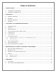
TABLE OF CONTENTS 1 2 3 4 5 SPECIFICATIONS ..................................................................................................................................................5 1.1 CVW-EXA284 / CVW-EXA224........................................................................................................................5 1.2 CVW-EXA184 / CPW-EXA124.........................................................................................................................6 DIMENSIONS...
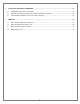
6 7 CARE AND CLEANING GUIDELINES.............................................................................................................21 6.1 EXTERIOR PANELS (DAILY CLEANING) ............................................................................................................21 6.2 MIRRORS, FLUORESCENT LAMPS, DRAIN TRAP (MONTHLY CLEANING) .........................................................21 6.3 HONEYCOMB ASSEMBLIES (AT LEAST EVERY 3 MONTHS) ........................................
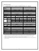
1 Specifications 1.1 CVW-EXA284 (H: 84 7/8”, L: 96 3/8”) / CVW-EXA224 (H: 84 7/8”, L: 144 5/8”) Model Name CVW-EXA284 CVW-EXA224 Application: Cooling Capacity: Discharge Air: Evaporator Temperature: Medium Temperature (Fresh Produce) 1224 BTU/h/ft. (2,880W) 34°F (1.11°C) 28°F (-2.22°C) Medium Temperature (Fresh Produce) 1224 BTU/h/ft. (4,321W) 34°F (1.11°C) 28°F (-2.
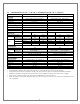
1.2 CVW-EXA184 (H: 80 7/8”, L: 96 3/8”) / CVW-EXA124 (H: 80 7/8”, L: 144 5/8”) Model Name CVW-EXA184 CVW-EXA124 Application: Cooling Capacity: Discharge Air: Evaporator Temperature: Medium Temperature (Fresh Produce) 1146 BTU/h/ft. (2682W) 34°F (1.11°C) 28°F (-2.22°C) Medium Temperature (Fresh produce) 1146 BTU/h/ft. (4195W) 34°F (1.44°C) 28°F (-2.
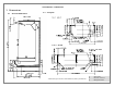
CVW-EXA284 / CVW-EXA224 2 Dimensions 2.1 External Dimensions 2.2 Footprint * Dimensions given in inches and millimeters (mm in parentheses).
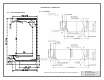
CVW-EXA184 / CVW-EXA124 2.3 External Dimensions 2.4 Footprint * Dimensions given in inches and millimeters (mm in parentheses).
3 Unloading and Carpentry Procedures 3.1 NSF Certification The SANYO Cases described in this manual are built to meet the requirements of American National Standard/NSF International Standard 7. Each SANYO Case bears a nameplate identifying the type of application for which it was certified: Type I display refrigerator/freezer: Intended for use in an area where the environmental conditions are controlled and maintained so that the ambient temperature typically does not exceed 75°F. 3.
3.5 Aligning Cases WARNING SANYO Cases are heavy and bulky, and require at least two people for unloading, moving, and installation. Do not walk on the top of the SANYO Cases. Walking on the top of the SANYO Case may lead to serious injury and/or damage to the SANYO Case. Do not place anything on the top of the SANYO Case or use the top of any SANYO Case for short- or long-term storage. 1. Review layout drawings for spaces where SANYO Cases are to be installed. 2.
3.7 3.7.1 Joining Instructions Applying gasket (for connecting cases or installing side panels). ① Make sure that all SANYO Cases are resting level. ② Make sure that all required parts for joining are present (gasket, bolts, joint covers, nuts, etc.). ③ Remove all Rear Interior Panels, Wire Racks, Deck Pans, and Front Air Grilles from the far right and left ends of each case being joined. ④ Thoroughly clean all surfaces where the gasket will be placed to remove anything that might affect adhesion.
3.7.2 Connecting cases. ① Apply gasket as described above. ② Connect cases by using the attached bolts, joint covers, and nuts. Silicone seal Note: Connection point must be silicone sealed. Note: Gasket ends that are open must be sealed off by applying silicone at the installation site.
3.8 Installing Patch Ends CVW-EXA284/224 ① Gasket ② M8 Bolts ③ Side Cover ④ Suction Lamp Cover Joint ⑤ M5 Bolts CVW-EXA184/124 1. 2. 3. 4. 5. 6. Apply gasket to case body (per previous instructions). If present, remove protective film from inside wall of Patch End. Place Patch End to line up with bolt holes. From inside unit ratchet in M8 & optional M5 bolt into Patch End until secure. Apply Silicone sealant between inside of Patch End and lower frame (see drawing to the left for details).
3.9 1. Installing Kickplate Align the mounting hole in the Kickplate with the slot in the Kickplate Mounting Bracket on the SANYO Case and tighten accordingly.
3.10 Installing Handrail and Bumper Attaching the Bumper 1. Attach Maintenance Bumper (length 39-3/8 inches) to Bumper Brackets over the electrical connection box (“Raceway”) on each SANYO Case. The Raceway is located on the right end of each SANYO Case. 2. Attach Full-Length Bumpers between Maintenance Bumpers on separate SANYO Cases, and also between Maintenance Bumpers and Patch Ends. 3. Cut Full-Length Bumpers to size on-site. Cut to correct size so that no gaps remain between pieces.
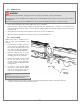
4 Refrigeration, Plumbing & Electrical Procedures 4.1 ● Piping (Plumbing, Refrigeration) U-trap installation Install U-trap referring to the drawing below. Part Name Part Number ① Drain Screen 8FL2162000500 ② O-Ring 8FL2646000100 ③ Drain Trap 8FL2658000200 ● Sealing the refrigerant pipe opening Seal pipe completely. Insufficient sealing may cause the following problems: Insufficient cooling Excessive frost Icing over Condensation on the bottom of case.
4.2 Electrical Data Please refer to Specifications section and nameplate attached to merchandiser for electrical information. 4.3 Electrical – Guidelines & Precautions All wiring and electrical field work must comply with the National Electrical Code (“NEC”) and other applicable local codes. All electrical connections must be made inside the raceway area. 4.4 4.4.
4.4.
5 Operation 5.1 Load Limits In order to maintain proper temperature and unit performance, the Dual Air Curtains in each SANYO Case must remain unobstructed: Do not stock shelves beyond the marked load limits. Do not block Honeycombs or Return Air Grilles. Do not block airflow in any other way (with signs, tools, packages, etc.) Failure to follow these precautions will lead to insufficient temperature control, airflow spoilage, merchandise compromise, and excessive frost.
Installing FDA/NSF Thermometer Magnet Suggested locations for the thermometer required by NSF/ANSI 7 and the FDA Food Code are indicated above. It is the responsibility of the Purchaser/End User of the SANYO Case to determine the location within the food storage area that best meets these code requirements.
6 Care and Cleaning Guidelines In order to keep SANYO Cases sanitary and in good working order, we recommend thorough periodic cleaning as follows: 6.1 Exterior Panels (Daily Cleaning) a. Exterior panels should be cleaned with water only. Wet a soft cloth and wring it out to wipe down panels. b. If required, you may use a mild detergent and warm water to remove stains. You should follow by wiping down with water only in order to prevent discoloration. c.
Please make sure to check and clean the drain trap at least once a month. Remove any material that has gathered in the drain trap and dispose of it. Clean the drain trap and put it back in its original position. 6.3 Honeycomb Assemblies (at least every 3 months) Because Honeycomb Assemblies may deform under pressure, DO NOT use vacuum cleaners to clean them. a.
7 Service 7.1 Replacing Fan Motors and Blades To replace the fan motors: ① Remove the outer Air Curtain Duct Cover and socket covers. ② Unplug the fan motor harness and push through hole in plenum. ③ Detach fan motor mounting bracket from plenum and pull up to remove. HAND PROTECTION REQUIRED! Activities to be undertaken require finger and palm protection to prevent personal injuries.
Fan Motor Assembly Part Numbers (Standard-Type Fan Motors) ①-a Hex Nut ①-b Spring Washer ①-c Round Washer ② Fan Blade ③ Fan Motor ④ Motor Mount ⑤ Bracket For models with Standard-type (AC) Fan Motors: No.
Fan Motor Assembly Part Numbers (High-Efficiency-Type Fan Motors) ①-a Hex Nut ①-b Spring Washer ①-c Round Washer ② Fan Blade ③ Fan Motor ④ Bracket For models with high-efficiency-type (DC) fan motors: No.
7.2 Replacing Electronic Ballasts Ballast Exterior Top Panel To replace electronic ballasts: ① Remove the Exterior Top Panel. ② Unplug the Electronic Ballast Harness(es). ③ Remove the Electronic Ballast(s).
7.3 Replacing Fluorescent Lamps The unit comes with covers placed over each fluorescent lamp. Ensure that these covers are placed over the new lamps before reinstallation. LAMP COVER END CAP LAMP CAUTION! Always use Sanyo lamp covers and end caps when replacing lamp covers and end caps. Using non-Sanyo brand replacement parts can result in decreased performance and/or part lifetime.
7.3 Expansion Valve Danfoss MODEL CVW-EXA124 CVW-EXA224 Valve Body P.N. 9FT2450000110 9FT2450000610 Body Type Refrigerant Valve Orifice P.N. R404A 9FT2450000100 R22/R422D 9FT2450000200 R404A 9FT2450000200 R22/R422D 9FT2450000200 TUAE 068U2287 TUAE 068U2237 CVW-EXA184 CVW-EXA284 9FT2450000210 TUA 068U2285 9FT2450000710 TUA 068U2235 Sporlan MODEL CVW-EXA124 CVW-EXA224 CVW-EXA184 CVW-EXA284 Valve Body P.N.
Marketed by: Manufactured and Distributed by: SANYO E & E Corporation 2001 Sanyo Avenue, San Diego, CA 92154-6229 USA Toll Free USA 800-95-SANYO (72696) · Fax 619-661-4183 http://us.sanyo.com/Food-Solutions ©2010 SANYO E & E Corporation MCVW V01.