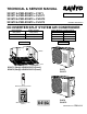
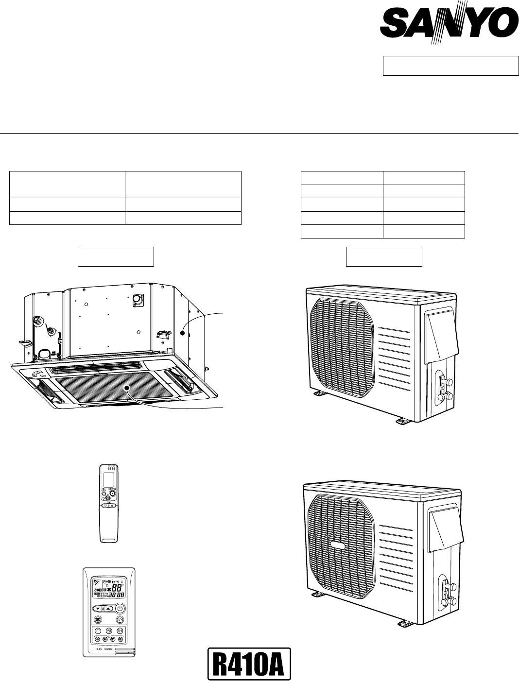
TECHNICAL & SERVICE MANUAL XS1271 & PNR-XS1872 + C1271 XS1271 & PNR-XS1872 + CL1271 XS1872 & PNR-XS1872 + CH1872 XS1872 & PNR-XS1872 + CL1872 FILE NO. Destination: North America DC INVERTER SPLIT SYSTEM AIR CONDITIONER Indoor Model No. Product Code No. XS1271 (PNR-XS1872) 1 852 352 10 (1 852 352 11) Body (Panel) XS1872 (PNR-XS1872) Outdoor Model No. Product Code No.
Important! Please Read Before Starting When Transporting Be careful when picking up and moving the indoor and outdoor units. Get a partner to help, and bend your knees when lifting to reduce strain on your back. Sharp edges or thin aluminum fins on the air conditioner can cut your fingers. This air conditioning system meets strict safety and operating standards. As the installer or service person, it is an important part of your job to install or service the system so it operates safely and efficiently.
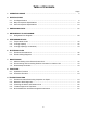
Table of Contents Page 1. OPERATING RANGE ................................................................................................................... 5 2. SPECIFICATIONS 2-1. Unit Specifications ............................................................................................................. 2-2. Major Component Specifications ....................................................................................... 2-3. Other Component Specifications .....................................
Page 10. CHECKING ELECTRICAL COMPONENTS 10-1. Measurement of Insulation Resistance ............................................................................... 10-2. Checking Continuity of Fuse on PCB Ass'y ......................................................................... 63 64 11. REFRIGERANT R410A: SPECIAL PRECAUTIONS WHEN SERVICING UNIT 11-1. Characteristics of New Refrigerant R410A ......................................................................... 11-2. Checklist before Servicing ...
1. OPERATING RANGE Models : XS1271 & PNR-XS1872 + C1271 XS1872 & PNR-XS1872 + C1872 Cooling Temperature Indoor Air Intake Temp. Minimum 67 °F D.B. / 57 °F W.B. Maximum 95 °F D.B. / 71 °F W.B. Models : XS1271 & PNR-XS1872 + CL1271 XS1872 & PNR-XS1872 + CL1872 Cooling Temperature Indoor Air Intake Temp. Minimum 67 °F D.B. / 57 °F W.B. Maximum 95 °F D.B. / 71 °F W.B. 5 Outdoor Air Intake Temp. 115 °F D.B. 67 °F D.B. Outdoor Air Intake Temp. 115 °F D.B. 0 °F D.B.
2. SPECIFICATIONS 2-1. Unit Specifications 2-1-1.
Indoor Unit Outdoor Unit XS1271 & PNR-XS1872 C1271 Indoor Unit (XS1271 & PNR-XS1872) Dimensions & Weight (Indoor Unit) Unit Dimensions Package Dimensions Weight Shipping Volume Height Width Depth Height Width Depth Net Shipping inch (mm) inch (mm) inch (mm) inch (mm) inch (mm) inch (mm) Ib. (kg) Ib. (kg) cu.ft (m3) 12-5/16 (313) 24-19/32 (625) 24-19/32 (625) 41.3 (18.
2-1-2. Indoor Unit Outdoor Unit XS1872 & PNR-XS1872 C1872 Features Electrical Rating Performance Voltage Rating 230V Single-Phase 60Hz Total Capacity Sensible Capacity Latent Capacity Air Circulation (High) Moisture Removal (High) Available Voltage Range Running Amperes Power Input Power Factor EER SEER Compressor Locked Rotor Amperes Fuse or Circuit Breaker Capacity Controls / Temperature Control Control Unit Timer Fan Speeds Airflow Direction (Indoor) Cooling 17,500 ( 4,000 to 17,500 ) 5.15 ( 1.
Indoor Unit Outdoor Unit XS1872 & PNR-XS1872 C1872 < 230V > Indoor Unit (XS1872 & PNR-XS1872) Dimensions & Weight (Indoor Unit) Unit Dimensions Package Dimensions Weight Shipping Volume Height Width Depth Height Width Depth Net Shipping inch (mm) inch (mm) inch (mm) inch (mm) inch (mm) inch (mm) Ib. (kg) Ib. (kg) cu.ft (m3) 12-5/16 (313) 24-19/32 (625) 24-19/32 (625) 41.3 (18.
2-1-3. Indoor Unit Outdoor Unit XS1872 & PNR-XS1872 C1872 Features Electrical Rating Performance Voltage Rating 208V Single-Phase 60Hz Total Capacity Sensible Capacity Latent Capacity Air Circulation (High) Moisture Removal (High) Available Voltage Range Running Amperes Power Input Power Factor EER SEER Compressor Locked Rotor Amperes Fuse or Circuit Breaker Capacity Controls / Temperature Control Control Unit Timer Fan Speeds Airflow Direction (Indoor) Cooling 17,500 ( 4,000 to 17,500 ) 5.15 ( 1.
Indoor Unit Outdoor Unit XS1872 & PNR-XS1872 C1872 < 208V > Indoor Unit (XS1872 & PNR-XS1872) Dimensions & Weight (Indoor Unit) Unit Dimensions Package Dimensions Weight Shipping Volume Height Width Depth Height Width Depth Net Shipping inch (mm) inch (mm) inch (mm) inch (mm) inch (mm) inch (mm) Ib. (kg) Ib. (kg) cu.ft (m3) 12-5/16 (313) 24-19/32 (625) 24-19/32 (625) 41.3 (18.
2-1-4. Indoor Unit Outdoor Unit XS1271 & PNR-XS1872 CL1271 Features Electrical Rating Performance Voltage Rating 115V Single-Phase 60Hz Total Capacity Sensible Capacity Latent Capacity Air Circulation (High) Moisture Removal (High) Available Voltage Range Running Amperes Power Input Power Factor EER SEER Compressor Locked Rotor Amperes Fuse or Circuit Breaker Capacity Controls / Temperature Control Control Unit Timer Fan Speeds Airflow Direction (Indoor) Cooling 11,900 ( 3,000 to 11,900 ) 3.5 ( 0.
Indoor Unit Outdoor Unit XS1271 & PNR-XS1872 CL1271 Indoor Unit (XS1271 & PNR-XS1872) Dimensions & Weight (Indoor Unit) Unit Dimensions Package Dimensions Weight Shipping Volume Height Width Depth Height Width Depth Net Shipping inch (mm) inch (mm) inch (mm) inch (mm) inch (mm) inch (mm) Ib. (kg) Ib. (kg) cu.ft (m3) 12-5/16 (313) 24-19/32 (625) 24-19/32 (625) 41.3 (18.
2-1-5. Indoor Unit Outdoor Unit XS1872 & PNR-XS1872 CL1872 Features Electrical Rating Performance Voltage Rating 230V Single-Phase 60Hz Total Capacity Sensible Capacity Latent Capacity Air Circulation (High) Moisture Removal (High) Available Voltage Range Running Amperes Power Input Power Factor EER SEER Compressor Locked Rotor Amperes Fuse or Circuit Breaker Capacity Controls / Temperature Control Control Unit Timer Fan Speeds Airflow Direction (Indoor) Cooling 17,500 ( 4,000 to 17,500 ) 5.15 ( 1.
Indoor Unit Outdoor Unit XS1872 & PNR-XS1872 CL1872 < 230V > Indoor Unit (XS1872 & PNR-XS1872) Dimensions & Weight (Indoor Unit) Unit Dimensions Package Dimensions Weight Shipping Volume Height Width Depth Height Width Depth Net Shipping inch (mm) inch (mm) inch (mm) inch (mm) inch (mm) inch (mm) Ib. (kg) Ib. (kg) cu.ft (m3) 12-5/16 (313) 24-19/32 (625) 24-19/32 (625) 41.3 (18.
2-1-6. Indoor Unit Outdoor Unit XS1872 & PNR-XS1872 CL1872 Features Electrical Rating Performance Voltage Rating 208V Single-Phase 60Hz Total Capacity Sensible Capacity Latent Capacity Air Circulation (High) Moisture Removal (High) Available Voltage Range Running Amperes Power Input Power Factor EER SEER Compressor Locked Rotor Amperes Fuse or Circuit Breaker Capacity Controls / Temperature Control Control Unit Timer Fan Speeds Airflow Direction (Indoor) Cooling 17,500 ( 4,000 to 17,500 ) 5.15 ( 1.
Indoor Unit Outdoor Unit XS1872 & PNR-XS1872 CL1872 < 208V > Indoor Unit (XS1872 & PNR-XS1872) Dimensions & Weight (Indoor Unit) Unit Dimensions Package Dimensions Weight Shipping Volume Height Width Depth Height Width Depth Net Shipping inch (mm) inch (mm) inch (mm) inch (mm) inch (mm) inch (mm) Ib. (kg) Ib. (kg) cu.ft (m3) 12-5/16 (313) 24-19/32 (625) 24-19/32 (625) 41.3 (18.
2-2. Major Component Specifications 2-2-1. Indoor Unit Indoor Unit (Body) XS1271 Control PCB Part No. Controls Control Circuit Fuse CB-XS1271 Microprocessor 250V 3A Remote Control Unit Fan RCS-7MVPS4U Type Q'ty ... Dia. and Length Turbo 1 ... D12-5/8 / L5-3/4 (D322/L147) inch (mm) Fan Motor Type Model ... Q'ty No. of Poles Rough Measure RPM (Cool) Rating Voltage / Nominal Output Ohm Coil Resistance (Ambient Temp.
Indoor Unit (Body) XS1872 Control PCB Part No. Controls Control Circuit Fuse CB-XS1872 Microprocessor 250V 3A Remote Control Unit Fan RCS-7MVPS4U Type Q'ty ... Dia. and Length Turbo 1 ... D12-5/8 / L5-3/4 (D322/L147) inch (mm) Fan Motor Type Model ... Q'ty No. of Poles Rough Measure RPM (Cool) Rating Voltage / Nominal Output Ohm Coil Resistance (Ambient Temp. 68 °F (20 °C)) Safety Device Type Over- Current Protection Over- Heat Protection Run Capacitor Micro F VAC DC Motor SIC-72FV-D866-1B ...
2-2-2. Outdoor Unit C1271 Outdoor Unit Control PCB Part No. Controls Control Circuit Fuse CB-C1271 Microprocessor 125V 25A Compressor Type Compressor Model / Nominal Output Pints (cc) Compressor Oil ... Amount Coil Resistance (Ambient Temp. 68 °F (20 °C)) Ohm DC Rotary (Hermetic) G4C090LU1ER / 900W FV50S ... 0.68 (320) U - V : 0.81 V - W : 0.81 W - U : 0.81 Safety Device CT (Peak current cut-off control) Compressor Discharge Temp.
C1872 Outdoor Unit Control PCB Part No. Controls Control Circuit Fuse CB-C1872 Microprocessor 250V 25A Compressor Type Compressor Model / Nominal Output Pints (cc) Compressor Oil ... Amount Coil Resistance (Ambient Temp. 68 °F (20 °C)) Ohm DC Twin Rotary (Hermetic) C-6RVN93H0M / 1,050W FV50S ... 0.74 (350) R - S : 0.482 S - T : 0.482 T - R : 0.482 Safety Device CT (Peak current cut-off control) Compressor Discharge Temp.
CL1271 Outdoor Unit Control PCB Part No. Controls Control Circuit Fuse CB-CL1271 Microprocessor 125V 25A Compressor Type Compressor Model / Nominal Output Pints (cc) Compressor Oil ... Amount Coil Resistance (Ambient Temp. 68 °F (20 °C)) Ohm DC Rotary (Hermetic) G4C090LU1ER / 900W FV50S ... 0.68 (320) U - V : 0.81 V - W : 0.81 W - U : 0.81 Safety Device CT (Peak current cut-off control) Compressor Discharge Temp.
CL1872 Outdoor Unit Control PCB Part No. Controls Control Circuit Fuse CB-CL1872 Microprocessor 250V 25A Compressor Type Compressor Model / Nominal Output Pints (cc) Compressor Oil ... Amount Coil Resistance (Ambient Temp. 68 °F (20 °C)) Ohm DC Twin Rotary (Hermetic) C-6RVN93H0M / 1,050W FV50S ... 0.74 (350) R - S : 0.482 S - T : 0.482 T - R : 0.482 Safety Device CT (Peak current cut-off control) Compressor Discharge Temp.
2-3. Other Component Specifications XS1271 & PNR-XS1872 XS1872 & PNR-XS1872 Outdoor Unit C1271 C1872 CL1271 CL1872 Indoor Unit • Indoor heat exchanger sensor (Model:PT2M-51H-S3) • Compressor temp sensor (C1271, CL1271...Model:DTN-TKS274Y TH2) (C1872, CL1872...
7-23/32 1-27/32 1 2 3 4 5 6 7 8 1-3/32 2-3/32 Less than 31/32 22-5/8 (575) 25/32 7 2 2 1 2 Less than 31/32 Fresh air intake duct connection port (dia. 3-7/8") Suspension bolt hole (4 - 1/2" x 1-1/8" hole) Power supply port Drain tube connection port VP20 (outer dia. 1") Refrigerant tubing (gas tube) dia. 1/2" (flared) Refrigerant tubing (liquid tube) dia.
Outdoor Unit C1271 CL1271 21-3/16 3-19/32 15/32 :1 5/ 16 12-7/16 10-7/16(265) Wide tube service valve dia.3/8" (9.52) 2-1/8 Narrow tube service valve dia.1/4" (6.
Outdoor Unit C1872 CL1872 5-11/32 15/32 13-5/32 11-7/32 (285) Wide tube service valve dia.1/2" (12.70) 2-17/32 Narrow tube service valve dia.1/4" (6.
4. REFRIGERANT FLOW DIAGRAM 4-1. Refrigerant Flow Diagram XS1271 & PNR-XS1872 Outdoor Unit C1271 CL1271 Indoor unit Outdoor unit Wide tube Wide tube service valve Accumulator Muffler High pressure switch H.P. Strainer Heat exchanger Heat exchanger O.D. 3/8" (9.52 mm) Compressor Indoor Unit Narrow tube Electric expansion valve Narrow tube service valve M Muffler O.D. 1/4" (6.
XS1872 & PNR-XS1872 Outdoor Unit C1872 CL1872 Indoor unit Outdoor unit Wide tube Wide tube service valve Accumulator Muffler High pressure switch H.P. Strainer Heat exchanger Heat exchanger O.D. 1/2" (12.7mm) Compressor Indoor Unit Narrow tube Electric expansion valve Narrow tube service valve M O.D. 1/4" (6.
5. PERFORMANCE DATA 5-1. Temperature Charts Indoor Unit XS1271 & PNR-XS1872 C1271 or CL1271 Outdoor Unit Cooling Characteristics (RH : 46%, Indoor fan speed : High fan) (60Hz, 115V) Low pressure at wide tube service valve psig(MPaG) (1) Low pressure performance chart Lo Fan 131 (0.9) ) 6°F (30°C ir Temp.8 Indoor A °C) 80°F (27 °C) 75°F (24 102 (0.7) 73 (0.5) 77 (25) (2) Operating current performance chart 15 Operating current (A) Hi Fan 86 (30) 95 (35) Outdoor inlet air D.B. temp.
Indoor Unit XS1872 & PNR-XS1872 C1872 or CL1872 Outdoor Unit Cooling Characteristics (RH : 46%, Indoor fan speed : High fan) (60Hz, 230V) Low pressure at wide tube service valve psig(MPaG) (1) Low pressure performance chart Lo Fan 131 (0.9) Hi Fan ) 6°F (30°C ir Temp.8 Indoor A °C) 80°F (27 °C) 75°F (24 102 (0.7) 73 (0.5) 77 (25) 86 (30) 95 (35) Outdoor inlet air D.B. temp.
5-2. Cooling Capacity Indoor Unit : XS1271 & PNR-XS1872 Outdoor Unit : C1271 or CL1271 Power Supply : 115V Single Phase 60Hz < Cooling Capacity > RATING CAPACITY: 11,900 BTU/h AIR FLOW RATE: INDOOR ENT. TEMP. oF (oC) W.B. 235 CFM OUTDOOR AMBIENT TEMP. oF (oC) D.B. 65 (18.3) 75 (23.9) 85 (29.4) 95 (35.0) 105 (40.6) 115 (46.1) TC 11,940 11,720 11,460 11,220 10,440 7,840 CI 0.80 0.93 1.06 1.16 1.25 1.07 72 (22.2) SHC 8,210 8,080 7,940 7,800 7,340 5,970 59 76 (24.
Indoor Unit : XS1872 & PNR-XS1872 Outdoor Unit : C1872 or CL1872 Power Supply : 230V Single Phase 60Hz < Cooling Capacity > RATING CAPACITY: 17,500 BTU/h AIR FLOW RATE: INDOOR ENT. TEMP. oF (oC) W.B. 341 CFM OUTDOOR AMBIENT TEMP. oF (oC) D.B. 65 (18.3) 75 (23.9) 85 (29.4) 95 (35.0) 105 (40.6) 115 (46.1) TC 17,650 17,300 16,900 16,470 15,920 10,250 CI 1.15 1.34 1.54 72 (22.2) SHC 12,120 11,920 11,660 59 76 (24.4) SHC 13,320 13,120 (15.0) 80 (26.
5-3. Cooling Capacity (Low Ambient) Indoor Unit : XS1271 & PNR-XS1872 Outdoor Unit : CL1271 Power Supply : 115V Single Phase 60Hz < Cooling Capacity (Low Ambient) > RATING CAPACITY: 11,900 BTU/h AIR FLOW RATE: INDOOR ENT. TEMP. oF (oC) W.B. 235 CFM OUTDOOR AMBIENT TEMP. oF (oC) D.B. 0 (-17.8) 5 (-15.0) 15 (-9.4) 25 (-3.9) 35 (1.7) 45 (7.2) 55 (12.8) TC 9,520 9,540 9,550 9,570 9,590 9,580 9,570 CI 0.48 0.51 0.48 0.46 0.47 0.52 0.56 72 (22.
Indoor Unit : XS1872 & PNR-XS1872 Outdoor Unit : CL1872 Power Supply : 230V Single Phase 60Hz < Cooling Capacity (Low Ambient) > RATING CAPACITY: 17,500 BTU/h AIR FLOW RATE: INDOOR ENT. TEMP. oF (oC) W.B. 341 CFM OUTDOOR AMBIENT TEMP. oF (oC) D.B. 0 (-17.8) 5 (-15.0) 15 (-9.4) 25 (-3.9) 35 (1.7) 45 (7.2) 55 (12.8) TC 14,930 14,970 14,980 14,970 15,000 15,040 15,030 CI 0.87 0.91 0.94 0.81 0.79 0.78 0.82 10,600 72 (22.
6. ELECTRICAL DATA 6-1. Electrical Characteristics Indoor Unit XS1271 & PNR-XS1872 Outdoor Unit C1271 Cooling Performance at Rating conditions Rating conditions: Indoor Unit Fan Motor Running amp. Power input Indoor air temperature: Outdoor air temperature: A W 0.21 18 Outdoor Unit Fan Motor + Compressor 115V Single-phase 60Hz 12.39 1,242 Complete Unit 12.6 1,260 80°F (26.7°C) D.B. / 67°F (19.4°C) W.B. 95°F (35°C) D.B.
Indoor Unit XS1872 & PNR-XS1872 Outdoor Unit C1872 Cooling Performance at Rating conditions Rating conditions: Indoor Unit Fan Motor Running amp. Power input Indoor air temperature: Outdoor air temperature: A W 0.15 22 Outdoor Unit Fan Motor + Compressor 230V Single-phase 60Hz 8.15 1,838 Rating conditions: Indoor Unit Fan Motor Running amp. Power input Indoor air temperature: Outdoor air temperature: Complete Unit 8.3 1,860 80°F (26.7°C) D.B. / 67°F (19.4°C) W.B. 95°F (35°C) D.B.
2 3 38 WHT RED BLK AC1 AC2 SI FERRITE CORE FM DP CONTROLLER 1 3 1 3 DP 3P (BLU) 3P (RED) BOX 1 2 3 4 5 6 7 1 2 3 4 5 6 7 PWM/POW 7P (RED) SERIAL 1 1 2P (WHT) 2 2 GRN RED WHT BRN RED ORG YEL PNK BLU VLT BOX 1 2 3 4 5 6 7 1 2 3 4 5 6 7 PWM/POW 7P (RED) 1 1 SERIAL 2 2 2P (WHT) 1 2 3 4 1 2 3 4 RC 4P (WHT) FLAP (R) 1 2 3 4 5 6 1 2 3 4 5 6 1 2 3 4 5 1 2 3 4 5 FLAP (W) 1 2 3 4 5 1 2 3 4 5 1 2 3 4 5 1 2 3 4 5 FLAP 5P (WHT) CONTROLLER 1 2 3 4 5 6 7 1 2 3 4 5 6 7 IND 7P (WHT) WHT BLK GRN BRN
Outdoor Unit C1271 To avoid electrical shock hazard, be sure to disconnect power before checking, servicing and/or cleaning any electrical parts.
Outdoor Unit CL1271 To avoid electrical shock hazard, be sure to disconnect power before checking, servicing and/or cleaning any electrical parts.
Outdoor Unit C1872 CL1872 To avoid electrical shock hazard, be sure to disconnect power before checking, servicing and/or cleaning any electrical parts.
7. MAINTENANCE Tab 7-1. Address Setting of the Remote Control Unit The address can be set in order to prevent interference between remote controllers when two indoor units are installed near each other. The address is normally set to "A." To set a different address, it is necessary to change the address on the second remote controller. Fig. 13 NOTE Once changed, you cannot restore the original address setting of the air conditioner. (1) Switch on the power source.
7-2. Disconnecting and Connecting Positive Connector for Outdoor Unit One of the two types of connectors illustrated at left is used. Their basic structure is the same for each. How to Disconnect Pull the cover upward Hold the resin connector cover, and pull the connector off. You cannot disconnect the connector by pulling the wire since it is locked inside. Always hold the cover to disconnect. (See illustration at left.
7-3. Disassembly Procedure To avoid electrical shock hazard, be sure to disconnect power before WARNING attempting to disassemble the unit. When a footstool, etc. is used for disassembling the indoor unit, be careful not to fall down. If you fall down, you might be injured seriously. 7-3-1. Remove the air intake grill. (1) Slide the 2 latches each to the corresponding arrow direction. (Fig. 1 and Fig. 2) Open downward the air intake grill located on the latch side.
7-3-3. Remove the ceiling panel. (1) Open the clamp (4 locations) and remove the 2 lead wires from the clamps. (Fig. 6) (2) Remove the 4 screws fixing the corner cover (at 3 locations) and indicator cover (at 1 location). (Fig. 6) (3) Press the center 1 of the cover and remove the cover with the section 2 pulled down. (Fig. 7) (4) Remove the strap (3 locations) from the hook on the ceiling panel. (Fig. 8) NOTE There is no strap on the indicator cover.
7-3-4. Remove the indoor air temperature sensor. (1) Disconnect the connector CN08 (ROOM 2P) in the control box and remove the indoor air temperature sensor. (Fig. 10) Indoor air temperature sensor CN08 Fig.10 7-3-5. Remove the power box and control box. (1) Remove a screw and remove the terminal cover. (Fig. 11) (2) Remove the 2 screws and remove the power box cover. (Fig. 11) (3) Disconnect the power lines (No. 1 and No. 2) / signal line (No. 3) and ground cable from the terminals in the power box.
(4) Disconnect the connector CN07 (DP 2P) in the power box. (Fig. 13) Remove a screw and disconnect the ground cable. (Fig. 13) (5) Disconnect the connector CN03 (DCM 6P) in the power box. (Fig. 14) (6) Remove the 4 screws and remove the power box. (Fig. 14) (7) Disconnect the connectors CN06 (FS 3P) and CN09 (COIL-1 2P) in the control box. (Fig. 15) (8) Remove the 2 screws and remove the control box. (Fig. 15) Screw Ground cable 1 2 3 CN07 Fig.13 Screw Screw Screw CN03 Screw Fig.
NOTE For the removal of the following components, perform any work after removing the indoor unit (main body) from the ceiling. Main body lower section Heat exchanger sensor Float switch Drain pump Turbo fan Heat exchanger Fan motor 1. Perform the work after draining the water to prevent the water leakage from the drain pan. • Put a bucket, etc., under the drain cap and remove the drain cap to drain the water. (Fig. 16) 2.
7-3-7. Remove the heat exchanger sensor. (1) Remove the heat exchanger sensor from the sensor holder. (Fig. 19) Heat exchanger sensor Holder Fig.19 7-3-8. Remove the drain pump and float switch. (1) Remove the 2 screws (Fig. 20) (2) Loosen the clamp and disconnect the drain hose from the drain pump. (Fig. 20) (3) Remove the drain pump from the main body upper section. (Fig. 20) (4) Remove a nut and remove the float switch. (Fig. 21) Drain pump Screw Float switch Nut Drain hose Clamp Fig.20 Fig.
7-3-9. Remove the turbo fan and fan motor. (1) Remove a nut and remove the turbo fan. (Fig. 22) (2) Remove the 2 screws and 3 nuts, and remove the fan motor. (Fig. 23) Turbo fan Screw Nut Nut Fan motor Fig.22 Fig.23 7-3-10. Remove the heat exchanger. (1) Remove the 3 screws. (Fig. 24) (2) Remove the 3 screws. (Fig. 25) (3) Remove the heat exchanger from the main body upper section with the heat exchanger lifted. Heat exchanger Screw Screw Main body upper section Screw Fig.24 Fig.
8. FUNCTIONS 8-1. Operation Functions Emergency operation SENSOR DRY Emergency operation is available when the remote controller malfunctions, has been lost, or otherwise cannot be used. During DRY operation, the system adjusts the room temperature and fan speed according to the conditions in the room, in order to maintain a comfortable room environment. SENSOR DRY operation DRY operation is as shown in the figure below.
HIGH POWER NIGHT SETBACK This function acts to raise the power but keeps the AC system in the same operating mode. This function is set with the HIGH POWER button on the remote controller. (It can be set regardless of the temperature and fan speed settings.) When NIGHT SETBACK operation is set, the temperature and fan speed settings will be adjusted automatically to allow comfortable sleep. When NIGHT SETBACK operation is set, " mark" appears on the remote controller.
8-2. Protective Functions Compressor discharge temperature control Freeze prevention This function controls the operation frequency to prevent the compressor discharge temperature from rising more than a specified temperature. Indoor heat exchanger temperature °F(°C) During COOL or DRY operation, freezing is detected and operation is stopped when the temperature of the indoor heat exchanger matches the conditions below. 1.
9. TROUBLESHOOTING 9-1. Precautions before Performing Inspection or Repair After checking the self-diagnostics monitor, turn the power OFF before starting inspection or repair. High-capacity electrolytic capacitors are used inside the outdoor unit controller (inverter). They retain an electrical charge (charging voltage DC 310V) even after the power is turned OFF, and some time is required for the charge to dissipate. Be careful not to touch any electrified parts before the controller LED (red) turns OFF.
(1) Self-diagnostics Lamps INDOOR UNIT OPERATION button OPERATION lamp TIMER lamp HIGH POWER lamp REMOTE CONTROL receiver Since the indications cover various units, the corresponding parts listed below may not be present in some models. .... OFF Indication on indoor unit OPERATION Timer HIGH POWER Code Diagnostics items ....
(2) If the self-diagnostics function fails to operate Check the indoor unit. • No indicators illuminate and the indoor fan does not rotate. • Check the power voltage. Blown Is the fuse blown? Normal Replace the circuit board or the fuse. Replace the controller. 9-3. Checking the Indoor and Outdoor Units (1) Checking the indoor unit No. 1 Control Use the remote controller to operate the unit in "TEST run" mode.
(3) Serial Communication Error Identification Procedure If the lamps on the main body show the following conditions after the completion of self-diagnostics, a communication error between the indoor unit and outdoor unit might be considered. In such a case, identify the breakdown section by using the following procedure. Refer to "Method of Self-Diagnostics" for the self-diagnostics procedure.
( Continued from the previous page A. ) A ( Continued from the previous page B. ) B Is the voltage of about DC22V to 24V given between the terminals 2 and 3 on the indoor unit terminal strip (Serial Communication Line) ? (Fig. 2) Yes No Defect in the indoor unit P.C. board Defect or connection error in the inter-unit cable Outdoor Unit 1. Turn OFF the power and wait until the power lamp (LED) of the outdoor unit controller is turned OFF. 2.
(3-2) Condition: E12 Troubleshooting Serial Communication Outdoor Unit 1 2 3 4 5 6 Power 1. Turn off the power and wait until the power lamp (LED) of the outdoor unit controller is turned OFF. 2. Disconnect the cable from the terminal 3 on the Outdoor unit terminal strip. (Fig. 6) 1 2 3 Indoor Unit Fig. 6 1. Turn ON the power and operate the system using the remote controller or the operation button on the indoor unit. 2. Perform the self-diagnosis five seconds after the operation start.
9-4. Trouble Diagnosis of Fan Motor 9-4-1. Indoor Fan Motor This indoor DC fan motor contains an internal control PCB. Therefore, it is not possible to measure the coil resistance, and the following procedure should be used to check the motor. To perform diagnosis, operate the unit in cooling mode with indoor fan speed "High". Next, make sure that the indoor unit receive the signals from the remote controller when the ON/OFF operation button is pressed.
9-4-2. Outdoor Fan Motor This outdoor DC fan motor contains an internal control PCB. Therefore, it is not possible to measure the coil resistance, and the following procedure should be used to check the motor. Perform the trouble diagnosis by Test Run mode described on Installation Instructions. Important: (A) Turn OFF the power before connecting or disconnecting the motor connectors.
9-5. Noise Malfunction and Electromagnetic Interference An inverter A/C operates using pulse signal control and high frequencies. Therefore, it is susceptible to the effects of external noise, and is likely to cause electromagnetic interference with nearby wireless devices. A noise filter is installed for ordinary use, preventing these problems. However, depending on the installation conditions, these effects may still occur. Please pay attention to the points listed below.
10. CHECKING ELECTRICAL COMPONENTS 10-1. Measurement of Insulation Resistance Ground wire Clip The insulation is in good condition if the resistance exceeds 1M ohm. Probe 10-1-1. Power Supply Cord Clamp the grounding wire of power cord with the lead clip of the insulation resistance tester and measure the resistance by placing a probe on either of the two power wires. (Fig. 1) Then also measure the resistance between the grounding and other power terminals. (Fig. 1) Fig.
10-2. Checking Continuity of Fuse on PCB Ass'y Fuse Remove the PCB Ass'y from the electrical component box. Then pull out the fuse from the PCB Ass'y. (Fig. 5) Check for continuity using a multimeter as shown in Fig. 6. PCB Ass'y Fig. 5 Fuse Fig.
11. REFRIGERANT R410A: SPECIAL PRECAUTIONS WHEN SERVICING UNIT 11-1. Characteristics of New Refrigerant R410A 11-1-1. What is New Refrigerant R410A? R410A is a new refrigerant that contains two types of pseudo-non-azeotropic refrigerant mixture. Its refrigeration capacity and energy efficiency are about the same level as the conventional refrigerant, R22. 11-1-2. Components (mixing proportions) HFC32 (50%) / HFC125 (50%) 11-1-3.
11-2. Checklist before Servicing Use a clutch-type flare tool for R410A or the conventional flare tool. Note that sizes of the resultant flares differ between these two tools. Where a conventional flare tool is used, make sure to observe A Specification (amount of extrusion) by using the flare spacer. Diameter of tube D Flare tool for R410A Dia.1/4" (6.35 mm) Specification A Conventional flare tool (for R22) 0 to 0.0196" Dia.3/8" (9.52 mm) 0.0472" (0 to 0.5 mm) Dia.1/2" (12.7 mm) Dia.5/8" (15.
11-3. Tools Specifically for R410A For servicing, use the following tools for R410A Tool Distinction Tool Name Gauge manifold Charging hose Gas leak detector Refrigerant cylinder Charging cylinder Refrigerant recovery unit Tools specifically for R410A Vacuum pump with anti-reverse flow (*1) (Solenoid valve-installed type, which prevents oil from flowing back into the unit when the power is off, is recommended.) Vacuum pump (*2)...can be used if the following adapter is attached.
11-5. In Case of Compressor Malfunction CAUTION Should the compressor malfunction, be sure to make the switch to a replacement compressor as quickly as possible. Use only the tools indicated exclusively for R410A. Specifically for R410A." See "11-3. Tools 11-5-1. Procedure for Replacing Compressor (1) Recovering refrigerant Any remaining refrigerant inside the unit should not be released to the atmosphere, but recovered using the refrigerant recovery unit for R410A.
(5) Recharging Configuration and characteristics of cylinders Be sure to charge the specified amount of refrigerant in liquid state using the service port of the wide tube service valve. The proper amount is listed on the unit's nameplate. Valve When the entire amount cannot be charged all at once, charge gradually while operating the unit in Cooling Operation. CAUTION Liquid Never charge a large amount of liquid refrigerant at once to the unit. This may cause damage to the compressor.
11-6. In Case Refrigerant is Leaking CAUTION Never attempt to charge additional refrigerant when refrigerant has been leaking from the unit. Follow the procedure described below to locate points of leaks and carry out repairs, then recharge the refrigerant. (1) Detecting Leaks Use the detector for R410A to locate refrigerant leak points.
11-7. Charging Additional Refrigerant 11-7-1. When Tubes are Extended Observe the proper amount of refrigerant as stated in this service manual or the installation manual that came with the indoor unit. Charge additional refrigerant in liquid state only. CAUTION Never charge additional refrigerant if refrigerant is leaking from the unit. Follow instructions given in "11-6. In Case Refrigerant is Leaking" and completely carry out repairs. Only then should you recharge the refrigerant. 11-8.
APPENDIX A INSTRUCTION MANUAL XS1271 & PNR-XS1872 + C1271 XS1271 & PNR-XS1872 + CL1271 XS1872 & PNR-XS1872 + C1872 XS1872 & PNR-XS1872 + CL1872 (OI-852-6-4181-108-00-0) A-1
00_XS1872_Cover.fm Page 1 Friday, August 15, 2008 6:33 PM XS1271 XS1872 COOL/DRY Model INSTRUCTION MANUAL Inverter-Controlled Split System Air Conditioner MODE D’EMPLOI Climatiseur de type séparé contrôlé par inverseur This air conditioner uses the new refrigerant R410A. Save These Instructions! Conserver ce mode d’emploi Pub.
01_XS1872_EN.fm Page 2 Thursday, September 25, 2008 8:31 PM FEATURES This air conditioner is an inverter type unit that automatically adjusts capability as appropriate. Details on these functions are provided below; refer to these descriptions when using the air conditioner. • Microprocessor Controlled Operation The interior compartment of the remote control unit contains several features to facilitate automatic operation, easy logically displayed for easy use.
01_XS1872_EN.fm Page 3 Thursday, September 25, 2008 8:31 PM PRODUCT INFORMATION If you have problems or questions concerning your Air Conditioner, you will need the following information. Model and serial numbers are on the nameplate on the bottom of the cabinet. Model No. __________________________________ Serial No.
01_XS1872_EN.fm Page 4 Thursday, September 25, 2008 8:31 PM NAMES OF PARTS UNIT DISPLAY AND OPERATION BUTTON INDOOR UNIT INDOOR UNIT Air intakes OPERATION button OPERATION lamp Air outlet (4 locations) TIMER lamp HIGH POWER lamp REMOTE CONTROL receiver Remote control unit IMPORTANT Refrigerant tubes OUTDOOR UNIT Drain hose Avoid using radio equipment such as mobile phone near (within 4 ft. (1.2 m)) the remote control receiver. Some radio equipment may cause malfunction of the unit.
01_XS1872_EN.fm Page 5 Thursday, September 25, 2008 8:31 PM REMOTE CONTROL UNIT (DISPLAY) Displayed when transmitting data Displayed when indoor unit sensor is in use Displayed when setting temperature Displayed when temperature is shown Displayed when setting timer Displayed when the time display is set to 12-hour time. Symbols (1) Operation mode (4) Timer MILD DRY .............................. 24-hour clock with ON/OFF program Timer ....................... COOL ....................................
01_XS1872_EN.fm Page 6 Thursday, September 25, 2008 8:31 PM REMOTE CONTROL UNIT Transmitter When you press the buttons on the remote control unit, the mark appears in the display to transmit the setting changes to the receiver in the air conditioner. Display Information on the operating conditions is displayed while the remote control unit is switched on. If the unit is turned off, FLAP setting and FAN SPEED setting are not displayed.
01_XS1872_EN.fm Page 7 Thursday, September 25, 2008 8:31 PM Sensor A temperature sensor inside the remote control unit senses the room temperature. ON/OFF operation button This button is for turning the air conditioner on and off. 1 HR. TIMER button (1-HOUR OFF TIMER) : When you press this button, regardless of whether the unit is operating or stopping, the unit operates for one hour and then shuts down. Temperature setting buttons (TEMP.) Press the button to increase the set temperature.
01_XS1872_EN.fm Page 8 Thursday, September 25, 2008 8:31 PM USING THE REMOTE CONTROL UNIT HOW TO INSTALL BATTERIES REMOTE CONTROL UNIT INSTALLATION POSITION The remote control unit may be operated either from a non-fixed position or from a wall-mounted position. To ensure that the air conditioner operates correctly, DO NOT install the remote control unit in the following places: DO NOT • In direct sunlight • Behind a curtain or other places where it is covered • More than 26 ft.
01_XS1872_EN.fm Page 9 Thursday, September 25, 2008 8:31 PM OPERATION WITH THE REMOTE CONTROL UNIT 1. Operation 2. Adjusting the Fan Speed A. Automatic fan speed Simply set the FAN SPEED selector button to the position. This automatically sets the best fan speed for the room temperature. B. Manual fan speed STEP 2 STEP 3 If you want to adjust fan speed manually during operation, just set the FAN SPEED selector button as desired. [ , , or ] 3.
01_XS1872_EN.fm Page 10 Thursday, September 25, 2008 8:31 PM 4. Night Setback Mode HIGH POWER mode can be used to increase the output of the indoor unit for all operation modes except automatic operation. Press the HIGH POWER button while operation. The mark appears in the display. To cancel, press HIGH POWER button again. • When the HIGH POWER button is pressed, the unit operates at maximum output for 30 minutes, regardless of the desired temperature. The fan speed is 1 step above “High”.
01_XS1872_EN.fm Page 11 Thursday, September 25, 2008 8:31 PM 1. How to set the present time Operation (Example) To set to 10:30 pm. Indication 1. Press the ON TIME setting button once. 2. Press the Advance, Return ( , ) button until AM 7:10 is displayed. Operation 1. Press the CLOCK button once if the time indicator is not flashing. Indication The time indication alone flashes. 2. Press the Advance, Return The time can be set in 1-minute ( , ) button until PM 10:30 increments.
01_XS1872_EN.fm Page 12 Thursday, September 25, 2008 8:31 PM USING THE 1-HOUR OFF TIMER 1. 1-Hour OFF Timer This function causes the unit to operate for one hour and then stop, regardless of whether the unit is on or off when this button is pressed. The indicator in the display indicates that this function is operating. Setting procedure: Regardless of whether the unit is operating or stopped, press the 1 HR. TIMER button. appears in the display.
01_XS1872_EN.fm Page 13 Thursday, September 25, 2008 8:31 PM OPERATION WITHOUT THE REMOTE CONTROL UNIT CARE AND CLEANING • Cleaning and maintenance operations must be carried out by specially trained personnel. While working in high places, slipping or falling may result in serious injury. • For safety, be sure to turn the air conditioner off and also to disconnect the power before cleaning. • Do not pour water on the indoor unit to clean it.
01_XS1872_EN.fm Page 14 Thursday, September 25, 2008 8:31 PM Air filter The air filter collects dust and other particles from the air and should be cleaned once every 6 months. If the filter gets blocked, the efficiency of the air conditioner drops greatly. How to remove the air intake grille 1. Open the air intake grille. 2. Detach the safety cord from the frame (remember to attach it again after cleaning or maintenance). 3.
01_XS1872_EN.fm Page 15 Thursday, September 25, 2008 8:31 PM TROUBLESHOOTING OPERATING RANGE If your air conditioner does not work properly, first check the following points before requesting service. If it still does not work properly, contact your dealer or service center. Trouble Air conditioner does not run at all. Possible Cause Remedy 1. Power failure. 1. Restore power. 2. Leakage circuit breaker tripped. 2. Contact service center. 3. Line voltage is too low.
APPENDIX B INSTALLATION INSTRUCTIONS XS1271 & PNR-XS1872 + C1271 XS1271 & PNR-XS1872 + CL1271 XS1872 & PNR-XS1872 + C1872 XS1872 & PNR-XS1872 + CL1872 (II-852-6-4190-478-00-0) A-2
08-221 XS1271 9/12/08 2:52 PM Page a INSTALLATION INSTRUCTIONS – Inverter Split System Air Conditioner – COOL / DRY Model This air conditioner uses the new refrigerant R410A. NOTE Refrigerant service valve size = 5/16" Contents Model Combinations Page Combine indoor and outdoor units only as listed below. IMPORTANT! Please Read Before Starting .................................. 2 1. 2. 3. GENERAL .......................................................... 3 1-1.
08-221 XS1271 9/12/08 2:52 PM Page 2 IMPORTANT! Please Read Before Starting When Installing… This air conditioning system meets strict safety and operating standards. As the installer or service person, it is an important part of your job to install or service the system so it operates safely and efficiently. …In a Ceiling or Wall Make sure the ceiling/wall is strong enough to hold the unit’s weight. It may be necessary to construct a strong wood or metal frame to provide added support.
08-221 XS1271 9/12/08 2:52 PM Page 3 1. General This booklet briefly outlines where and how to install the air conditioning system. Please read over the entire set of instructions for the indoor and outdoor units and make sure all accessory parts listed are with the system before beginning. 1-1. Tools Required for Installation (not supplied) 1. Standard screwdriver 6. Sabre saw or key hole saw 2. Phillips head screwdriver 7. Hacksaw 3. Knife or wire stripper 8. Core bits 4. Tape measure 9. Hammer 5.
08-221 XS1271 9/12/08 2:52 PM Page 4 1-5. Additional Materials Required for Installation 1. 2. Refrigeration (armored) tape Insulated staples or clamps for connecting wire (See local codes) Putty Refrigeration lubricant Clamps or saddles to secure refrigerant tubing 3. 4. 5. 2. Installation Site Selection 2-1.
9/12/08 2:52 PM Page 5 2-2. Outdoor Unit NO AVOID: Hot air G heat sources, exhaust fans, etc. (Fig. 3) G damp, humid or uneven locations. Heat source Outdoor unit DO: choose a place that is well ventilated. G install in a location where at least two sides are unobstructed, so that the flow of air at the intake port or exhaust port is not blocked, and so that sufficient space is ensured for maintenance to be carried out without trouble. In general the top also must be unobstructed. (Figs.
08-221 XS1271 9/12/08 2:52 PM Page 6 2-3. Baffle Plate for the Outdoor Unit (CLxx models only) Air intake baffle Wind NOTE It is recommended to use baffle plates for models CL1271 and CL1872. The baffle plates are not normally required for the other models. Front When the outdoor unit is installed in a position exposed to strong wind (such as seasonal winds with low air temperature in winter), baffle plates must be installed on the outdoor unit. (Fig.
08-221 XS1271 9/12/08 2:52 PM Page 7 I CL1271 (1) Recommended dimensions of the baffle plates Air Intake Baffle Air Discharge Baffle N H A 2(2- J 2(2- I J B H 15/64" 6 mm) C K M 1/4" 6.5 mm) G L 4(4- 1/4" 6.5 mm) Q K P C G I E A G E D F D B F Fig. 5d Fig. 5e For Air Intake Dimensions Model CL1271 A B (inch) 21-21/32 25/32 (mm) C D 2-5/32 17-5/16 E F G H I J K N P 13 25/64 19/32 23/64 19/64 17-3/8 550 20 55 440 330 10 15 9 7.
08-221 XS1271 9/12/08 2:52 PM Page 8 I CL1872 (1) Recommended dimensions of the baffle plates Air Intake Baffle Air Discharge Baffle H O A 2- 15/64" (2- 6 mm) I J B H C J 3(3- K 1/4" 6.5 mm) 4(4- 1/4" 6.5 mm) G C R L E Q I D A K E G F F D B G Fig. 5f Fig. 5g For Air Intake Dimensions E F G H I J K (inch) 24-13/32 25/32 1-25/32 22-1/4 (mm) Model CL1872 A B C D 9-1/4 9-1/4 25/64 25/32 19/32 23-1/8 19/64 620 20 45 565 235 235 10 20 15 587 7.
08-221 XS1271 9/12/08 2:52 PM Page 9 (3) Installation procedure I CL1271 1. Air Intake Baffle 2. Air Discharge Baffle (1) Left side 1. Remove the panels front, side L and R from the unit and drill 4 holes of ø1/4 inch (6.5 mm) at the prescribed positions. 1. Remove the front panel from the unit. 2. Remove the panel side L, and drill 2 holes of ø1/4 inch (6.5 mm) at the prescribed position. 2. Install the windbaffle on the unit using field supply bolts and nuts. 3.
08-221 XS1271 9/12/08 2:52 PM Page 10 I CL1872 1. Air Intake Baffle 2. Air Discharge Baffle (1) Left side 1. Remove the panels front, top, side L and R from the unit and drill 4 holes of ø1/4 inch (6.5 mm) at the prescribed positions. 1. Remove the top panel from the unit. 2. Remove the panel side L, and drill 3 holes of ø1/4 inch (6.5 mm) at the prescribed positions. 2. Install the windbaffle on the unit using field supply bolts and nuts. 3.
08-221 XS1271 9/12/08 2:52 PM Page 11 3. How to Install the Indoor Unit Hole-in-anchor Hole-in-plug Concrete Insert 3-1. Preparation for Suspending This unit uses a drain pump. Use a carpenter’s level to check that the unit is level. 3-2.
08-221 XS1271 9/12/08 2:52 PM Page 12 Twist tie (4 vinyl ties, supplied) 3-4. Installing the Drain Piping (1) Prepare standard hard PVC pipe (locally purchased O.D. 1-1/32" (26 mm)) for the drain and use the supplied hose band to prevent water leaks. (Fig. 6-5) Drain port Drain hose insulation (supplied) Hard PVC pipe Position to (equivalent to O.D.
08-221 XS1271 9/12/08 2:52 PM Page 13 3-5. Checking the Drainage After wiring and drain piping are completed, use the following procedure to check that the water will drain smoothly. For this, prepare a bucket and wiping cloth to catch and wipe up spilled water. G Water drain Be sure to do the wiring between the units before installing the ceiling panel. (Refer to 3-9. Wiring Instructions for Inter-unit Connections) (1) Turn on the power.
08-221 XS1271 9/12/08 2:52 PM Page 14 (2) Removing the corner cover and indicator cover a) While lightly pressing the center of the corner cover, pull up the tab for the screw hole. Use the same procedure to remove the indicator cover. (Fig. 6-16) 1 Press Corner cover 2 Pull up Indicator cover Fig. 6-16 3-6-2.
08-221 XS1271 9/12/08 2:52 PM Page 15 3-6-3. Wiring the Ceiling Panel and the Indicator Drain pipe side (1) Remove the 2 screws from the control box cover, then open the cover. Be careful that the cover does not fall. (2) Connect the 5P FLAP wiring connector from the ceiling panel to the connector on the control PCB in the control box. (Fig.
08-221 XS1271 9/12/08 2:52 PM Page 16 3-6-5. Checking After Installation G Check that there are no gaps between the unit and the ceiling panel, or between the ceiling panel and the ceiling surface. Gaps may cause water leakage and condensation. G Check that the wiring is securely connected. If it is not securely connected, the auto flap will not operate. In addition, water leakage and condensation may occur. 3-6-6.
08-221 XS1271 9/12/08 2:52 PM Page 17 Table 4 Cross-Sectional Area (AWG) Model (A)+(B) (A) Power Supply Wiring Length (ft) (B) Power Line Length (ft) (C) Control Line Length (ft) Fuse or Circuit Breaker Capacity (#14) (#12) (#14) C1271, CL1271 131 (Max.) 230 (Max.) 65 (Max.) 20A C1872, CL1872 131 (Max.) 230 (Max.) 98 (Max.) 20A # ...
08-221 XS1271 9/12/08 2:52 PM Page 18 3-9. Wiring Instructions for Inter-unit Connections (1) Remove the 1 screw from the terminal cover, then open the cover. Be careful that the cover does not fall. (2) Remove the 3 screws from the power box cover, then open the cover. Be careful that the cover does not fall. (4) Remove the transparent plastic cover from the 3P terminal plate.
08-221 XS1271 9/12/08 2:52 PM Page 19 I For stranded wiring (1) Cut the wire end with a cutting pliers, then strip the insulation to expose the stranded wiring about 3/8" (10 mm) and tightly twist the wire ends. (Figs. 11 and 12) (2) Using a screwdriver, remove the terminal screw(s) on the terminal plate. (3) Using a ring connector fastener or pliers, securely clamp each stripped wire end with a ring connector. (Fig.
08-221 XS1271 9/12/08 2:52 PM Page 20 5. Refrigerant Tubing Deburring After Before 5-1. Use of the Flaring Method Many of the conventional split system air conditioners employ the flaring method to connect refrigerant tubes which run between indoor and outdoor units. In this method, the copper tubes are flared at each end and connected with flare nuts. 5-2. Flaring Procedure with a Flare Tool (1) Cut the copper tube to the required length with a tube cutter. It is recommended to cut approx.
08-221 XS1271 9/12/08 2:52 PM Page 21 5-4. Connecting Tubing between Indoor and Outdoor Units a) b) Torque wrench Tightly connect the indoor side refrigerant tubing extended from the wall with the outdoor side tubing. (Fig. 21) Spanner Indoor unit To fasten the flare nuts, apply specified torque as: Outdoor unit Table 5 Tube Dia. Fig. 21 Tightening Torque 1/4" (6.35 mm) Approx. 120 – 160 lbs·in (140 – 180 kgf·cm) 3/8" (9.52 mm) Approx. 300 – 360 lbs·in (340 – 420 kgf·cm) 1/2" (12.
08-221 XS1271 9/12/08 2:52 PM Page 22 5-6. Taping the Tubes (1) At this time, the 2 refrigerant tubes (and electrical wire if local codes permit) should be taped together with armoring tape. The drain hose may also be included and taped together as 1 bundle with the tubing. (2) Wrap the armoring tape from the bottom of the outdoor unit to the top of the tubing where it enters the wall. As you wrap the tubing, overlap half of each previous tape turn. (Fig.
08-221 XS1271 9/12/08 2:52 PM Page 23 (4) With the “Lo” knob of the manifold valve open, run the vacuum pump. The operation time for the vacuum pump varies with tubing length and the capacity of the pump. The following table shows the amount of time for evacuation: NOTE To prevent other refrigerants from being mistakenly charged to units which use R410A, the size of the charge port on the service valve is different from the one for other refrigerant types.
08-221 XS1271 9/12/08 2:52 PM Page 24 How to Test Run the Air Conditioner After turning on the power of the air conditioner, use the remote controller and follow the steps below to conduct the test run. (1) Set the remote controller in Test Run mode. (Fig. 29) a)Press and hold the HIGH POWER button and the 1HR. TIMER button. b)Then press and hold the ACL (Reset) button with a pointed object such as the tip of a pen. After 5 seconds, release the ACL button first.
08-221 XS1271 I 9/12/08 2:52 PM Page 25 Basic Functions of the Service Valves The basic functions of the service valves are given in Table 7 below.
08-221 XS1271 I 9/12/08 2:52 PM Page 26 Service Valve Connections a) Temporary connection: Screw in 3 – 5 turns by hand. (Fig. 34) b) To fasten the flare nuts, apply specified torque as Table 8 and Fig. 35. Table 8 Tube Dia. Fig. 34 Tightening Torque 1/4" (6.35 mm) Approx. 120 – 160 lbs·in (140 – 180 kgf·cm) 3/8" (9.52 mm) Approx. 300 – 360 lbs·in (340 – 420 kgf·cm) 1/2" (12.70 mm) Approx. 430 – 540 lbs·in (490 – 610 kgf·cm) 5/8" (15.88 mm) Approx.
08-221 XS1271 9/12/08 2:52 PM Page 27 8. Address Switch Tab 8-1. Address Setting of the Remote Control Unit The address can be set in order to prevent interference between remote controllers when 2 indoor units are installed near each other. The address is normally set to “A.” To set a different address, it is necessary to change the address on the second remote controller. NOTE Fig. 37 Once changed, you cannot restore the original address setting of the air conditioner.
APPENDIX C INSTRUCTION MANUAL STK-RCS-7TWSU (OI-852-6-4181-119-00-0) A-3
00_STK-RCS-7TWSU_Cover.fm Page 1 Thursday, August 21, 2008 12:04 PM STK-RCS-7TWSU INSTRUCTION MANUAL Wired Remote Controller This wired remote controller is designed for both the “COOL/DRY/HEAT Model” and “COOL/DRY Model” indoor unit. Before using the remote controller, be sure to confirm the “model type” specified on the front cover of the INSTRUCTION MANUAL supplied with the indoor unit. MODE D’EMPLOI Télécommande Filaire Save These Instructions! Conserver ce mode d’emploi Pub.
01_STK-RCS-7TWSU_EN.fm Page 2 Tuesday, October 14, 2008 1:48 PM CONTENTS Page PRODUCT INFORMATION ................................................................................................................ 2 ALERT SYMBOLS .............................................................................................................................. 2 INSTALLATION LOCATION ................................................................................................................
01_STK-RCS-7TWSU_EN.fm Page 3 Tuesday, October 14, 2008 1:48 PM REMOTE CONTROL UNIT (DISPLAY) Displayed when indoor unit sensor is in use Displayed when operating NIGHT SETBACK mode Displayed when setting temperature Displayed when temperature is shown Displayed when setting timer Symbols (1) Operation mode AUTO ..................................... (only for COOL/DRY/HEAT Model) HEAT ...................................... (only for COOL/DRY/HEAT Model) (3) Temperature setting 60 – 86 °F ...............
01_STK-RCS-7TWSU_EN.fm Page 4 Tuesday, October 14, 2008 1:48 PM REMOTE CONTROL UNIT NOTE The descriptions on the AUTO ( “COOL/DRY Model.” ) or HEAT ( ) operation mode are only for the “COOL/DRY/HEAT Model,” and not for the Display Information on the operating conditions is displayed while the remote control unit is switched on. If the unit is turned off, only the mode that was set previously is still displayed. Temperature setting buttons (TEMP.) Press the button to increase the set temperature.
01_STK-RCS-7TWSU_EN.fm Page 5 Tuesday, October 14, 2008 1:48 PM ON/OFF operation button This button is for turning the air conditioner on and off. MODE selector button Use this button to select AUTO, HEAT, DRY, COOL or FAN mode. (AUTO) : When this setting is selected, the air conditioner calculates the difference between the thermostat setting and the room temperature and automatically switches to the ‘‘COOL’’ or ‘‘HEAT’’ mode as appropriate.
01_STK-RCS-7TWSU_EN.fm Page 6 Tuesday, October 14, 2008 1:48 PM OPERATION WITH THE REMOTE CONTROL UNIT 1. Automatic Operation (only for COOL/DRY/HEAT Model) 2. Manual Operation This unit automatically switches between cooling operation and heating operation according to the difference between the room temperature and the temperature setting. STEP 2 STEP 3 STEP 4 STEP 1 STEP 2 STEP 5 STEP 1 NOTE NOTE Check that the circuit breaker on the power panel is turned on.
01_STK-RCS-7TWSU_EN.fm Page 7 Tuesday, October 14, 2008 1:48 PM 3. Adjusting the Fan Speed A. In Cooling and DRY Mode: ( A. Automatic fan speed Simply set the FAN SPEED selector button to the position. This automatically sets the best fan speed for the room temperature. B.
01_STK-RCS-7TWSU_EN.fm Page 8 Tuesday, October 14, 2008 1:48 PM SETTING THE TIMER 3. How to set the ON time (Example) To start operation at 7:10 am. ON TIME Present time Operation Indication 1. Press the SET button once. The timer indication alone flashes and the previous settime is only displayed. 2. • Press the HH button until The display will change automatically back to show the present time after about 10 sec. AM 7 is displayed. • Press the MM button until 10 is displayed. 1.
01_STK-RCS-7TWSU_EN.fm Page 9 Tuesday, October 14, 2008 1:48 PM 5. Cancellation of the time setting You can cancel the time settings by pressing the TIMER SELECT button. The time settings cannot be canceled by pressing the ON/OFF operation button or MODE selector button. 6. Backup function Even if the main power supply (circuit breaker) is cut off, the capacitor inside the remote control store the mode settings in the memory for 3 hours after the power is off.
APPENDIX D INSTALLATION INSTRUCTIONS STK-RCS-7TWSU (II-852-6-4190-481-00-0) A-4
08-230 STK-RCS-7TWSU 9/29/08 10:23 AM Page 1 INSTALLATION INSTRUCTIONS STK-RCS-7TWSU (Wired Remote Controller) I Parts supplied with the remote controller Table 1 Parts See Table 1. I Remote controller installation guidelines Installation location • Mount the remote controller 3.3 to 4.9 ft. (1 to 1.5 meters) off the floor where it can sense the average temperature of the room.
10:23 AM Page 2 A. Installing with in-wall junction box (1) Install the junction box (locally purchased) into the wall. (Figs. 2-a and 3) (2) Pass the wire harness through the junction box and conduit. (Fig. 3) (3) Insert a flathead screwdriver into the 5 tab locations and disconnect the back plate of the remote controller by lifting up slightly. (Fig. 2-b) The tabs are thin; take care not to chip them.
10:23 AM Page 3 I How to wire the remote controller Ceiling panel (1) Turn OFF the power and remove the ceiling panel air-intake grille. (Refer to 3-6-1 Before Installing the Ceiling Panel in the Installation Instructions supplied with the indoor unit.) (2) Remove the 3 power box cover screws and 2 control box cover screws, then remove both covers. At this time, take care not to drop the covers. (Fig.
08-230 STK-RCS-7TWSU 9/29/08 10:23 AM Page 4 I How to Test Run the Air Conditioner After turning on the power of the air conditioner, use the remote controller and follow the steps below to conduct the test run. (1) Set the remote controller in Test Run mode. (Fig. 9) a)Press and hold the NIGHT SETBACK button and the 1HR. TIMER button. b)Then press and hold the ACL (Reset) button with a pointed object such as the tip of a pen. After 5 seconds, release the ACL button first.
SANYO Commercial Solutions A Division of SANYO North America Corporation 1300 Michael Drive, Suite A Wood Dale, IL 60191, U.S.A. Sanyo Canada Inc. 1-300 Applewood Crescent, Concord, Ontario L4K 5C7, CANADA Nov.