FILE NO. Mechanism Manual 3CD Changer Mechanism PM-CDC10TP This manual explain how to remove and assemble by 10 illustration as follows. May help the service manual of DC-C10, C30, C50, C70 Series, Note: A name in this explanation uses a name mentioned in mechanism number fist. Q Operate it in number order.
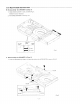
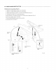
3 CD MECHANISM INSTRUCTION B. Disassembly the DRAWER 2 (Step 1) 1. Slide CM SLIDER 1 bask and Drawer's lock is released. 2. Pull CM DRAWER 2 half way out. L SLIDER 1 CM GEN L C. Disassembly the DRAWER 2 (Step 2} Fig.1 1. Push the DRAWER up a little, and push the other side of DRAWER to remove (Fig.
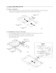
CD MECHANISM INSTRUCTION D. Position confirmation 1. Rotate CM BEVEL GEAR 4 1o check CR12/CM13 {or C14) CARRIAGE movement and position, 1f iris good, two carriages are the same position at the end (front position) (Fig.3). BEVEL GEAR Cre N NO.2 CARRIAGE CM N1 CARRIAGE 7 . comic S Fig 3 E. If CARRIAGE was slid out of the drawer, 1 Turn CM BEVEL GEAR 4 to rotate CM CARRIAGE LIFT until it stops once {Fig.d) 2. Place 13 CARRIAGE No.2 3. Turn CM BEVEL GEAR 4 to slide the carriage into its position.
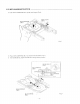
3 CD MECHANISM INSTRUCTION 4. Push CM CARRIAGE No 2 up with your fingers (Fig.6}. BEVEL GEAR NO.2 CARRIAGE Fig.6 5. Place GM CARRIAGE No.1 as shown in the illustration {Fig.7) 6. Tum CM BEVEL GEAR 4 to slide the cartage info its position. BEVEL GEAR 4 CM NOLA CARRIAGE CM NO.2 CARRIAGE M3 Fig.
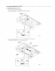
3 CD MECHANISM INSTRUCTION F. CARRIAGE Playback position if the CARRIAGE is wrong position, 1, Slide CM SLIDER 1 to it CM CAMPER up (Fig.81. CAMPER oMz SUNDER 1 CM OPEN e Fig.8 2. Place CM CARRIAGE No.3 on GM CARRIAGE LIFT UP (Fig.9) 3. Slide CM SLIDER 1 back to its original position CAMPER o2 LIFTER Chan NO.3 CARRIAGE Jem SLIDER 3 ©M35 / Fig.
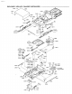
3 CD MECHANISM INSTRUCTION G.Mechanism Assembly (Fig.10) 1. Make sure CM BEVEL GEAR 4 s in the place. 2. Make sure CM GEAR IDLER A2 sin the place. 3. Match CM BEVEL GEAR 1 as shown in the illustration {Fig. 11}, 4. Assemble the right side of CM DRAWER 2. 5. Insert Section A and slid it toward font as shown int the illustration (Fig 12). 6. Push it into COMO SAYS CHASSIS 7. Push COMO DRAWER 2 back into the position. 8. Assemble CM COVER 2.
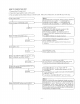
HOW TO CHECK THE UNIT 1, Connect the AC power cord. 2. Press the Power switch to turn on the power, 3. The unit will be set into Initial settings as shown below. I the units malfunction, the unit will stop in the step. Turn on the power Discriminates CARRIAGE switch Motor CARRIAGE (CM) drive Notes: Discriminates the carriage No. of the Cartilage switches *Push the front side switch —= CARRIAGE No.1 *Push the rear side switch —« CARRIAGE No.2 *Push the both side switches —= CARRIAGE No.
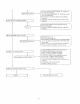
i Rotates MOTOR DRAWER (CM) inactive Moves DRAWER toward CLOSE Confirm to al LAY mode or not Goon Displacement scours DRAWER will not move Not complete an initial operation *The gear inside HOUSEHOLDER) "R” engaged at the displaced position “The gear of HOUSEHOLDER} "R™ displaced with the gear of CARRIAGE *PC BOARD B and Home switch circuit (CM) defective *Control #C BOARD attached in the final process defective *PC BOARD (CMO6,07) incompletely soldered "MOTOR defective *Control PC BOARD (COMO) attached in