e00_l8hbe_xe_nw_7.
e00_l8hbe_xe_nw_7.book Page 1 Monday, April 26, 2004 10:40 AM CONTENTS NETWORK CONTROL Controlling from a PC ..................................... 5 Controlling from the unit ................................. 7 Messages displayed when connected ........... 7 1 NETWORK CONTROL FUNCTION .............. 2 Operations possible with PC control .............. 2 Network settings ............................................ 2 3 OPERATION PANEL FUNCTIONS AND RESTRICTIONS....................................
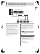
e00_l8hbe_xe_nw_7.book Page 2 Monday, April 26, 2004 10:40 AM 1 NETWORK CONTROL FUNCTION PC control (i.e., remote control) will be possible when this unit is connected to a network.
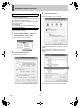
e00_l8hbe_xe_nw_7.book Page 3 Monday, April 26, 2004 10:40 AM 1 NETWORK CONTROL FUNCTION 3 Installing DVR Viewer Click “Custom Level...”. The “Security Settings” screen is displayed. (1) Double-click the DVR Viewer’s “Setup.exe” icon in order to launch the installer. After several moments, the “InstallShield Wizard” window will be displayed and installation will start. When installation has ended, the “Maintenance Complete” window will be displayed. (2) Click [Finish].
e00_l8hbe_xe_nw_7.book Page 4 Monday, April 26, 2004 10:40 AM 1 NETWORK CONTROL FUNCTION 5 Click [Properties]. The [General] tab window in the [Internet Protocol (TCP/ IP) Properties] window is displayed. Computer: PC/AT compatible machine Operating system: Windows 98/98SE/Me/NT4.0/2000/XP Browser: Internet Explorer Ver. 5.
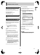
e00_l8hbe_xe_nw_7.book Page 5 Monday, April 26, 2004 10:40 AM 2 PREPARING FOR NETWORK CONTROL 3 Controlling from a PC 1 Launch the PC’s web browser. Enter a password (for verification purposes). Enter a [User name] and a verification-use [Password] on the [Connect to 192.168.0.1] screen, and then click [OK]. If you entered an incorrect password, the password entry screen will appear once again and you will be prompted to re-input the password. Internet Explorer versions 5.0 and later are supported.
e00_l8hbe_xe_nw_7.book Page 6 Monday, April 26, 2004 10:40 AM 2 4 PREPARING FOR NETWORK CONTROL Entering the operation screen NETWORK CONTROL (1) The following screen will be displayed when password verification has been completed successfully. (2) Select the language and click [OK]. The operation screen will be displayed and computer control will now be possible.
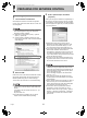
e00_l8hbe_xe_nw_7.book Page 7 Monday, April 26, 2004 10:40 AM 2 PREPARING FOR NETWORK CONTROL 2 Controlling from the unit Whenever the button on the PC’s operation screen is clicked, access will be cancelled and control rights will switch back to the unit. When control rights are switched to the unit Whenever the button on the PC’s operation screen is clicked, access will be cancelled and control rights will switch back to the unit.
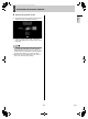
e00_l8hbe_xe_nw_7.book Page 8 Monday, April 26, 2004 10:40 AM 3 OPERATION PANEL FUNCTIONS AND RESTRICTIONS Operation panel NETWORK CONTROL 9. Playback stop (ID2/3) This button stops playback and calls up the live display. 10. Playback (ID2/3) This button starts playback of recorded images. 1 11. Previous image (ID2/3) This button moves a still image back by one frame. 2 3 12. Still (ID2/3) This button pauses the image during playback. 9 4 5 6 7 8 10 11 13 12 14 16 19 15 20 21 17 13.
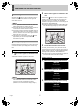
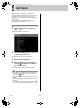
e00_l8hbe_xe_nw_7.book Page 9 Monday, April 26, 2004 10:40 AM 1 SETTINGS Before using the unit, settings should be made for recording conditions, installation environment, and other similar factors. The corresponding menu items are displayed in a two-level structure comprising main menus and sub-menus. For more details regarding setting methods, see “2. MENU-SPECIFIC SETTINGS” (JP. 11). Making menu selection 1 Click the panel. button on the operation The MAIN MENU screen is displayed.
e00_l8hbe_xe_nw_7.book Page 10 Monday, April 26, 2004 10:40 AM 1 SETTINGS Menu structure Main menu z CLOCK SET 11 2. SUMMER TIME SET/ EXT. CLOCK SET z SUMMER TIME SET z EXT. CLOCK SET 11 3. HOLIDAY SET z HOLIDAY SET 12 z AREA FULL RESET 5. RECORDING CONDITIONS SET z NORMAL RECORDING AREA OVERWRITE z ALARM RECORDING AREA OVERWRITE z REMAINING DISK WARNING z AUTO DELETE 14 6. NORMAL REC MODE SET z PICTURE QUALITY z AUDIO RECORDING z REC RATE z PROGRAM GROUP 15 7.
e00_l8hbe_xe_nw_7.book Page 11 Monday, April 26, 2004 10:40 AM 2 MENU-SPECIFIC SETTINGS 1. CLOCK SET 2. SUMMER TIME SET/EXT. CLOCK SET Set the unit’s time and date as described below. Be sure that the date and time are set correctly at this time. 1 Select the “Day/Month/Year/Hour/ Minutes” field from the pull-down menu on the screen. 1 2 3 The day of the week will be set automatically based on the date.
e00_l8hbe_xe_nw_7.book Page 12 Monday, April 26, 2004 10:40 AM 2 MENU-SPECIFIC SETTINGS 3. HOLIDAY SET NETWORK SETTINGS Set specific days as holidays using the procedure described below. When a day is specified as a holiday, timer recording for that day will be carried out as if it were a Sunday. Dates such as national holidays and company off days should be set as holidays when you want those dates to have the same security as Sundays.
e00_l8hbe_xe_nw_7.book Page 13 Monday, April 26, 2004 10:40 AM 2 MENU-SPECIFIC SETTINGS 4. RECORDING AREA SET The unit’s hard disk is separated into three independent recording areas. Furthermore, five different recording modes can be used for these three areas. The memory capacity for each area is allocated as a percentage.
e00_l8hbe_xe_nw_7.book Page 14 Monday, April 26, 2004 10:40 AM 2 MENU-SPECIFIC SETTINGS 5. RECORDING CONDITIONS SET Setting the remaining-space warning level 1 2 3 3 4 5 Setting range: 1% to 10% (in units of 1%) Setting overwriting permission for the normal recording area Setting the auto delete You can set the storage period for images. When the set period has expired, the corresponding data will be automatically deleted.
e00_l8hbe_xe_nw_7.book Page 15 Monday, April 26, 2004 10:40 AM 2 MENU-SPECIFIC SETTINGS 6. NORMAL REC MODE SET Setting the recording rate Set the recording rate for normal recording as follows. (Default setting: A15 FPS) Set conditions for normal recording and timer recording as described below. 3 1 Select “REC RATE” for normal recording from the pull-down menu on the screen. 2 3 4 5 Audio recording is carried out A60, A30, A20, A15, A10, A7.5, A6, A5, A4.286, A3.75, A3.333, A3, A2.727, A2.
e00_l8hbe_xe_nw_7.book Page 16 Monday, April 26, 2004 10:40 AM 2 MENU-SPECIFIC SETTINGS 4 7. PROGRAM REC SET When monitoring a number of cameras connected to this digital video recorder, a separate recording rate can be set for each camera. In addition, video recorded from each camera and the corresponding recording rates can be set in programs with up to four patterns, thus facilitating the simple specification of programs for timer-setting and normal recording setting menus.
e00_l8hbe_xe_nw_7.book Page 17 Monday, April 26, 2004 10:40 AM 2 MENU-SPECIFIC SETTINGS 8. TIMER SET Set timer operation duration and timer recording conditions on a day-specific basis as shown below. (1) (2) (3) (4) (5) (6) (7) For setting timer recording spanning more than 24 hours (8) 2 1 2 Setting timer recording conditions for different days of the week. Timer setting (or modification) is completed. (1) WEEK These fields specify the days of the week for timer recording.
e00_l8hbe_xe_nw_7.book Page 18 Monday, April 26, 2004 10:40 AM 2 MENU-SPECIFIC SETTINGS 9. ALARM REC MODE SET Setting the picture quality for recording Set the picture quality for alarm recording as follows. Set the recording conditions for alarm recording as follows. Setting alarm recording In order to carry out alarm recording, it will be necessary to set operation patterns and recording conditions. 6 5 1 2 NETWORK SETTINGS 2 3 4 Select “PICTURE QUALITY” from the pull-down menu on the screen.
e00_l8hbe_xe_nw_7.book Page 19 Monday, April 26, 2004 10:40 AM 2 MENU-SPECIFIC SETTINGS ONLY 5 Video is recorded only from cameras with an alarm occurring. Setting pre-alarm recording Set the recording conditions to be used for pre-alarm recording as described below. (JP. 25) Select “REC RATE” from the pull-down menu on the screen. (Default setting: A15 FPS) Audio recording is performed A30, A20, A15, A10, A7.5, A6, A5, A4.286, A3.75, A3.333, A3, A2.727, A2.308, A2, A1.667, A1.429, A1.25, A1.
e00_l8hbe_xe_nw_7.book Page 20 Monday, April 26, 2004 10:40 AM 2 MENU-SPECIFIC SETTINGS 10. DISPLAY SET Setting alarm triggers Set the alarm triggers (i.e., launch signals) that constitute operation conditions for alarm recording as follows. Set conditions for the display of data on the unit’s monitor by selecting “ON” or “OFF” for each item.
e00_l8hbe_xe_nw_7.book Page 21 Monday, April 26, 2004 10:40 AM 2 MENU-SPECIFIC SETTINGS 11. BUZZER SET Set a warning buzzer to sound for alarms or when the hard disk space reaches zero as described below. 1 To sound a buzzer on the PC z Create a folder named “BUZZER” within the root directory of the PC's C drive. z Within this folder, save the sound to be used as a buzzer in .wav format and with the name “BUZZER.WAV”. Example: C:\BUZZER\BUZZER.
e00_l8hbe_xe_nw_7.book Page 22 Monday, April 26, 2004 10:40 AM 2 MENU-SPECIFIC SETTINGS 12. HDD SET (1) (2) (3) 13. NETWORK SET Network settings must be made in advance on the unit whenever it is to be controlled via a network. Once this has been done, settings can then be changed from the controlling PC. (1) Hard disk capacity This item displays the total capacity of the hard disk. If hard disk expansion is carried out, a value will be displayed for each disk.
e00_l8hbe_xe_nw_7.book Page 23 Monday, April 26, 2004 10:40 AM 2 MENU-SPECIFIC SETTINGS 14. RS-485 SET z If a value other than “80” is set as the default value for the port, when specifying the URL, enter a colon (:) and then the port number after the IP address. For example, if the port number was set as “81”, you should enter http://192.168.0.1:81/ This screen displays settings relevant to the unit’s interfaces.
e00_l8hbe_xe_nw_7.book Page 24 Monday, April 26, 2004 10:40 AM 2 MENU-SPECIFIC SETTINGS 15. MASK SET 16. POWER FAILURE/USED TIME Check the date and time of power failures and the amount of hard disk usage as described below. Use the following procedure to set video from individual cameras to be masked by a gray pattern when it is not needed on a monitor screen. (1) NETWORK SETTINGS (1) (2) (3) (2) 2 1 Setting (1) MASK Description Item Turns masking on or off.
e00_l8hbe_xe_nw_7.book Page 25 Monday, April 26, 2004 10:40 AM 1 RECORDING IMAGES This section will describe the way in which monitored images and alarm images can be stored on the unit’s internal hard disk. Before any of these operations can be carried out, it will be necessary to make menu settings to match the installation environment. (JP. 10) Canceling timer recording 3 With “TIMER STANDBY” displayed, click the button on the operation panel.
e00_l8hbe_xe_nw_7.book Page 26 Monday, April 26, 2004 10:40 AM 1 RECORDING IMAGES (4) AUDIO (Default setting: OFF) Sound can be played in live mode or play mode. * Set only for full screen monitoring. Screen display items (8) (6) (9) (10) [Settings] Setting (7) OFF Description Audio will not be played. Audio will be played. Set the audio delay (5, 10, 15, 20, or 30 seconds). In Play mode, the speed of fast-forward and frame advance may be affected by the network environment being used.
e00_l8hbe_xe_nw_7.book Page 27 Monday, April 26, 2004 10:40 AM 1 RECORDING IMAGES (8) NORMAL RECORDING MODE This item displays the current condition for normal recording. z STOP z RECORDING z TIMER STANDBY z TIMER RECORDING z AREA FULL (in normal recording area) (9) ALARM RECORDING MODE This item displays the current condition for alarm recording.
e00_l8hbe_xe_nw_7.book Page 28 Monday, April 26, 2004 10:40 AM 2 WATCHING IMAGES Monitored live images and recorded images can be viewed freely and whenever so required. Note that switching to live or playback images, modifying the screen display, and other similar operations have absolutely no effect on timer recording and alarm recording. Interference may appear on images or the playback may seem to have paused during the following operations; however, this is normal and no cause for concern.
e00_l8hbe_xe_nw_7.book Page 29 Monday, April 26, 2004 10:40 AM 2 WATCHING IMAGES Specifying the number of screens to display Performing operations in play mode When a number of cameras are connected to the digital video recorder, it is possible to monitor video from several of these in multi-screen format. Use the following procedures to specify the channel numbers for the cameras to be displayed and the number of screens. Playback Click the [CHANNEL] button.
e00_l8hbe_xe_nw_7.book Page 30 Monday, April 26, 2004 10:40 AM 2 WATCHING IMAGES (6) Live mode image (Multi channels) (8) (9) (10) (6) Play mode image (1 channel) (11) (8) (9) (12) (7) (7) (1) (1) (3) (2) (5) Setting OFF 2 400 × 300 5 1,024 × 768 3 640 × 480 6 1,280 × 960 Audio will not be played. Audio will be played. Set the audio delay (5, 10, 15, 20, or 30 seconds). In Play mode, the speed of fast-forward and frame advance may be affected by the network environment being used.
e00_l8hbe_xe_nw_7.book Page 31 Monday, April 26, 2004 10:40 AM 2 WATCHING IMAGES Screen display items Settings for downloading live images to a PC (6) Image mode LIVE: Live mode PLAY: Play mode z If video with audio is to be downloaded to a PC, DVR Viewer must be installed before the necessary settings can be made. (JP. 2) (7) Time Live mode: Displays the current time Play mode: Displays the recording time (8) NORMAL RECORDING MODE This item displays the current condition for normal recording.
e00_l8hbe_xe_nw_7.book Page 32 Monday, April 26, 2004 10:40 AM 2 3 WATCHING IMAGES Set “DURATION”. To cancel a save operation Click [CANCEL]. The duration for images to be saved to the PC should be set in units of one minute. 4 (2) A pop-up window will be displayed when saving has been completed. The final still image from the save process will be displayed. Click [BROWSE]. A dialog box for selecting save location will be displayed, and a suitable location should be set.
e00_l8hbe_xe_nw_7.book Page 33 Monday, April 26, 2004 10:40 AM 3 SEARCH MODE Images stored in the recording areas can be searched and played back in search mode. Furthermore, five different search methods are available for doing so. Basic operation 1 2 In live mode (When playback is stopped), click the button on the operation panel. Select and click the desired search mode from the SEARCH screen. The screen for the selected search mode is displayed. The SEARCH screen is displayed.
e00_l8hbe_xe_nw_7.book Page 34 Monday, April 26, 2004 10:40 AM 4 OPERATIONS IN SEARCH MODES 1. ALARM SEARCH 2. ALARM THUMBNAIL SEARCH In alarm thumbnail search mode, all of the alarm images stored in the alarm recording area are displayed as thumbnails. Accordingly, you can search and play back alarm images using their thumbnails. In alarm search mode, images recorded in the alarm recording area are presented as a list of alarm numbers.
e00_l8hbe_xe_nw_7.book Page 35 Monday, April 26, 2004 10:40 AM 4 OPERATIONS IN SEARCH MODES 5 3. TIME/DATE SEARCH In date/time search mode, images from the normal recording area or the alarm recording area can be played back by specifying the corresponding date and time. (1) Click the preview screen for the image to be played back. Full-screen playback will start. 4. ARCHIVE AREA SEARCH (5) In archive area search mode, you can play back recorded images stored (or copied) to the archive area.
e00_l8hbe_xe_nw_7.book Page 36 Monday, April 26, 2004 10:40 AM 4 OPERATIONS IN SEARCH MODES 1 5. MOTION DETECTION SEARCH The motion detection search screen is displayed. By setting images recorded in the hard disk’s normal recording area or alarm recording area to the motion sensor, variations from these images as a result of the presence of an intruder or the like can be detected, and the corresponding images can be played back. (4) Select “5. MOTION DETECTION SEARCH” from the SEARCH menu.
e00_l8hbe_xe_nw_7.
e00_l8hbe_xe_nw_7.book Page 38 Monday, April 26, 2004 10:40 AM 5 SAVING RECORDED IMAGES Downloading to a PC z Due to Internet Explorer limitations, the number of images to download must be set so that all downloads will be completed within approximately 5 minutes. Use the following procedure to download recorded images to a PC. (2) 5 (1) Select the “AUDIO”. [Settings] ( indicates default setting.) Setting ON Image audio will be copied.
e00_l8hbe_xe_nw_7.book Page 39 Monday, April 26, 2004 10:40 AM 5 SAVING RECORDED IMAGES * Image viewer screen This screen allows you to check images that have been downloaded. (4) (5) (6) (7) (12) (3) (2) (1) (8) (13) (9) (10) (14) (11) (15) Thumbnail (1) [TOP] Displays the first image. (10) IMAGE NUMBER Displays the number of the image currently being played back. (2) [PREV.] Moves to the previous image.
e00_l8hbe_xe_nw_7.book Page 40 Monday, April 26, 2004 10:40 AM 1 DVR VIEWER 3 The DVR Viewer is a program designed specifically for DVRs. It can be used to play back image and sound data that has been copied onto media such as computer hard disk drives, CompactFlash cards. The DVR Viewer can be downloaded from the Sanyo website at the URL given below. Sanyo website URL: http://www.sanyosecurity.
e00_l8hbe_xe_nw_7.book Page 41 Monday, April 26, 2004 10:40 AM 1 DVR VIEWER Opening and closing DVR Viewer Closing DVR Viewer Click the close button in the top-right corner of the program window, or select [Exit (X)] from the [File (F)] menu to close DVR Viewer. Opening DVR Viewer From the Start menu, select [Programs] → [DVR Viewer] → [DVR Viewer] in the sequence to start the program. When DVR Viewer starts up, the following default window appears.
e00_l8hbe_xe_nw_7.book Page 42 Monday, April 26, 2004 10:40 AM 1 DVR VIEWER Toolbar This contains commands that are most often used. (1) (2) z To play back sound, be sure to specify a folder that contains “WAV” files. z This digital video recorder does not support the “Open images on CD-R” option in the dialog box. (3) To open images on a CD-R, select the CD-R drive name in question using the “Open a folder with JPEG images” in the dialog box.
e00_l8hbe_xe_nw_7.book Page 43 Monday, April 26, 2004 10:40 AM 1 DVR VIEWER Viewing images When image files are opened, the images that have been loaded appear. The display window consists of a main window and a thumbnail window, and you can use various operations in these windows such as a slideshow. (1) Time stamp 01/ 01/ 2004 10:15:10 (3) 01/01/2004 10:15:10 (2) 000001.jpg 000002.jpg 000003.jpg 000004.jpg 000005.
e00_l8hbe_xe_nw_7.book Page 44 Monday, April 26, 2004 10:40 AM 1 DVR VIEWER (3) Control panel This is used for playback operations in the main window and to adjust the images. (1) (2) (3) (4) (5) (6) (7) (8) (9) (10) 01/01/2004 10:15:10 (11) (12) (13) (14) (9) IMAGE SIZE (Default setting: 1) The display size for images in the main window can be set to one of five sizes. To display large image, select higher values. (1) [TOP] Moves to the start of a slideshow.
e00_l8hbe_xe_nw_7.book Page 45 Monday, April 26, 2004 10:40 AM 1 DVR VIEWER 4 Printing images To display titles for the images being printed, select [Title Input (T)] from the [File (F)] menu to display the Title Input dialog box. Specified images can be printed as full screens together with date and time information. 1 To display titles To print the image in the main window Select [Print (P)] from the [File (F)] menu, or click the icon on the toolbar. The Windows print dialog box appears.
e00_l8hbe_xe_nw_7.
e00_l8hbe_xe_nw_7.