OWNER'S MANUAL ECD-T1550 • PLL Synthesizer Stereo Radio • Digital Compact Disc Player • Automatic Memory Storing • Motorized Hidden Panel • Preset Equalization • Auxiliary Input Jack • Credit Card Remote Control • Multi-Color LCD • Plays CD-R/RW discs
CONTENTS Installation......................................3 Repeating the same track ............11 Take out screw before installation ...3 Playing all tracks in random .........11 DIN Front-Mount (Method A) ...........3 Ejecting a disc..............................11 Installing the unit ..........................3 Disc notes........................................11 Removing the unit ........................4 Specification....................................12 DIN Rear-Mount (Method B)..........
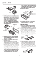
INSTALLATION Notes: TAKE OUT SCREW BEFORE INSTALLATION • Choose the mounting location where the unit will not interfere with the normal activity of the driver. Before install the unit, please remove the two screws. Take out screw before installation • Before finally installing the unit, connect the wiring temporarily and make sure it is all connected up properly. Test to see if the system is working properly. • Use only the parts included with the unit to ensure proper installation.
INSTALLATION metal strap to a solid metal part of the vehicle under the dashboard. This strap also helps ensure proper electrical grounding of the unit. Sleeve L Key Spring Washer Hex Nut Metal Strap Mounting Bolt R Key Plain Washer Tapping Screw 4. Mount the sleeve by inserting the sleeve into the opening of the dashboard and bend open the tabs located around the sleeve with a screwdriver. Not all tabs will be able to make contact, so examine which ones will be most effective.
INSTALLATION DIN REAR-MOUNT (Method B) 3 1 2 4 6 5 Tab 1. 2. 3. 4. Factory-installed radio bracket Car radio mounting bracket Screw After aligning the car radio mounting bracket with the factory-installed radio bracket, tighten the screws (M5x4mm) at 2 places on each side. 5. When fixing factory-installed radio bracket with the screws, use a standard-tipped screwdriver to pry the tabs of the car radio mounting bracket to make them fit into the holes in the factory-installed radio bracket. 6.
USING THE FRONT PANEL 3. Insert a disc in the disc slot, the panel will automatically turn up to State 2. Press (eject) button again, the panel will turn down to eject the disc. If you don’t insert a disc in again, the panel will automatically turn up after 10 seconds. If you don’t want to wait, press (eject) button, the panel will also turn up. 1. When the ignition key is switched to “ACC ON”, the panel of the unit will change from State 1 to State 2 (see below), the hidden panel will turn up. 4.
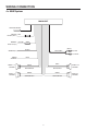
WIRING CONNECTION 4 x 50W System MAIN UNIT ANTENNA SOCKET IGNITION RED SWITCH (ACC+) MEMORY BACK-UP (B+) GROUND (B–) YELLOW (GREY) BLACK RCA CABLE Rch RED Lch WHITE POWER ANTENNA FRONT Lch SPEAKER REAR Lch SPEAKER BLUE WHITE GREY WHITE/BLACK GREY/BLACK GREEN VIOLET GREEN/BLACK VIOLET/BLACK 7 FRONT Rch SPEAKER REAR Rch SPEAKER
OPERATION 27 10 23 24 11 9 3 14 8 2 1 18 19 20 21 22 5 8 12 4 13 6 16 17 7 15
OPERATION SWITCHING ON/OFF THE UNIT When the hidden panel turns up (in State 2), switch the unit on by pressing any button (except button (4)). When system is on, press (9) to turn the unit off. SOUND ADJUSTMENT Press SEL button (10) to select the desired adjustment mode. The adjustment mode will change in the following order: VOL (Volume) BAS (Bass) TRE (Treble) BAL (Balance) FAD (Fader) By pressing VOLUME + button (11) or VOLUME- button (27), it is possible to adjust the desired sound quality.
OPERATION RADIO OPERATION • SWITCHING TO RADIO MODE Press MOD button (6) shortly to select radio mode, the radio mode appears in the display together with the memory band and frequency. • AUTOMATIC MEMORY STORING & PROGRAM SCANNING - Automatic Memory Storing Press AMS button (18) for several seconds, the radio searches from the current frequency and checks the signal strength until one cycle search is finished. The six strongest stations will be stored into the corresponding preset number button.
OPERATION If a CD is already inserted in the player: Keep pressing MOD button (6) shortly until the CD mode display appears. DISC NOTES A. Notes on discs: • Attempting to use non-standard shape discs (e.g. square, start, heart) may damage the unit. Be sure to use round shape CD discs only for this unit. • Do not stick paper or tape etc., onto the label side or the recording side of any discs, as it may cause a malfunction. • Dirt, dust, scratches and warping discs will cause misoperation.
SPECIFICATION GENERAL Power Supply Requirements Chassis Dimensions Tone Controls - Bass (at 100 Hz) - Treble (at 10 KHz) Maximum Output Power Current Drain : DC 12 Volts, Negative Ground : 178 (W) x 165 (D) x 50 (H) : : : : ± 10 dB ± 10 dB 4 x 50 Watts 15 Ampere (max.) CD PLAYER Signal to Noise Ratio Channel Separation Frequency Response : More than 55 dB : More than 45 dB : 40 Hz - 18 KHz RADIO Frequency Coverage IF Sensitivity (S/N=30dB) Stereo Separation : : : : : FM 87.5 to 107.9 10.
TROUBLE SHOOTING Before going through the check list, check wiring connection. If any of the problems persist after check list has been made, consult your nearest service dealer. Symptom No power. Disc cannot be loaded or ejected. Cause Solution The car ignition switch is not on. If the power supply is properly connected to the car accessory circuits, but the engine is not moving, switch the ignition key to “ACC”. The fuse is blown. Replace the fuse. Presence of CD disc inside the player.
SANYO MOBILE AUDIO MODEL ECD-T1550 LIMITED WARRANTY OBLIGATIONS In order to obtain warranty service, the product must be delivered to and picked up from an Authorized Sanyo Factory Service Center at the user’s expense, unless specifically stated otherwise in this warranty. The names and addresses of Authorized Sanyo Service Centers may be obtained by calling the toll-free number listed below.
21605 Plummer Street Chatsworth, CA91311 ECD-T1443. Issue Number 1.