File No : SUPPLEMENT OF SER VICE MANUAL SERVICE Micr owave Oven Microwave EM-A5200SW (U.S.A.) Pr oduct Code No. Product 437 557 00 See the Service Manual of EM-F3400SW (SM-860304) except the items described in this Service Manual. CAUTION WARNING TO SER VICE TECHNICIANS SERVICE PRECAUTIONS TO BE OBSERVED BEFORE AND DURING SERVICING TO AVOID POSSIBLE EXPOSURE TO EXCESSIVE MICROWAVE ENERGY (a) Do not operate or allow the oven to be operated with the door open.
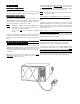
In the area emitting the highest reading, switch the meter to SLOW RESPONSE, and take a reading for minimum of three (3) seconds. We recommended the pattern outline shown below when the door surface is surveyed. CAUTION For micr owave ener gy emission microwave energy On every service calls, check for microwave energy emission, must be made according to the following manner.
- TABLE OF CONTENTS Specifications .................................................................. Power Output Measurement ........................................... Circuit Diagram ............................................................... 1 1 2 Test Procedures ...................................................... Exploded View and Parts List ................................ Overall Circuit Diagram .......................................... 3 4~ 9 10 1.
3.
4. TEST PROCEDURES COMPONENT CHECKOUT PROCEDURE RESUL RESULTT Measure the resistance between terminals of FPC connector after removing it from S101. (Figure 2). NOTE - When reconnecting the FPC connector, make sure the holes on the connector are properly inserted in hooks of the plastic fastener in S101. TOUCH KEY BOARD Resistance value When touched When not touched Less than 1K Ohms More than 1 MEG Ohms When checking “START” key, connect Ohm-Meter as illustration below.
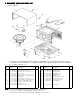
5 . EXPLODED VIEW AND P AR TS LIST PAR ARTS CAVITY PARTS *** Key No. 1 2 3 4 5 6 7 8 9 10 11 12 13 ALL SERVICE ON MICROWAVE OVENS SHOULD BE PERFORMED BY A QUALIFIED TECHNICIAN USING APPROVED TESTING EQUIPMENT. CUSTOMERS SHOULD NOT ATTEMPT TO REPLACE PARTS IDENTIFIED BY A TRIPLE ASTERISK (***). Part No.
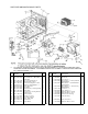
SWITCHES AND MICROWAVE PARTS *** Key No. ALL SERVICE ON MICROWAVE OVENS SHOULD BE PERFORMED BY A QUALIFIED TECHNICIAN USING APPROVED TESTING EQUIPMENT. CUSTOMERS SHOULD NOT ATTEMPT TO REPLACE PARTS IDENTIFIED BY A TRIPLE ASTERISK (***). Part No.
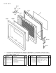
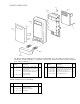
DOOR PARTS *** Key No. ALL SERVICE ON MICROWAVE OVENS SHOULD BE PERFORMED BY A QUALIFIED TECHNICIAN USING APPROVED TESTING EQUIPMENT. CUSTOMERS SHOULD NOT ATTEMPT TO REPLACE PARTS IDENTIFIED BY A TRIPLE ASTERISK (***). Part No. Description 1 2 3 617 236 5374 617 169 8800 617 228 9069 4 617 124 6490 Door Cover*** Door Panel*** Door Main Frame*** (Also order Door Sheet when replacing Door Main Frame) Choke Dielectric*** Key No. Q’ty 1 1 1 5 6 7 8 9 10 1 -6- Description Part No.
CONTROL PANEL PARTS *** Key No. ALL SERVICE ON MICROWAVE OVENS SHOULD BE PERFORMED BY A QUALIFIED TECHNICIAN USING APPROVED TESTING EQUIPMENT. CUSTOMERS SHOULD NOT ATTEMPT TO REPLACE PARTS IDENTIFIED BY A TRIPLE ASTERISK (***). Part No.
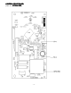
CONTROL CIRCUIT BOARD (Part No.
CONTROL CIRCUIT BOARD (Part No. 617 236 5305 5305) Key No. Order Part No. Description Key No. Q’ty 409 494 0900 IC LM8915-1R77. 1 TRANSISTORS Q901 405 138 8506 TR FMA9A. 1 Q103 Q101,102 405 035 4809 405 137 5803 2SC1685-Q-TP. DTA123YSA-TP. 1 2 Q105 405 004 3000 2SA564A-Q-TP. 1 R106 401 012 4404 Carbon, 100 ohms 11 ~ 14 +-5%, 1/4W. R101, 112 401 012 5609 Carbon, 1K ohms +-5%, 1/4W. R54, 56 401 013 6308 Carbon, 12K ohms +-5%, 1/4W. R105 Q’ty D11 407 012 0200 1N4002-TP.
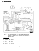
6 . OVERALL CIRCUIT DIAGRAM For Parts or Service Contact JULY 2000. 1200 LT Printed in Singapore - 10 - SANYO FISHER SER VICE COMP ANY SERVICE COMPANY 21605 Plummer Street, Chatsworth, CA91311 U.S.A.
File No : SER VICE MANUAL SERVICE Micr owave Oven Microwave EM-F3400SW Pr oduct Code No. Product (U.S.A.) 437 450 57 CAUTION WARNING TO SER VICE TECHNICIANS SERVICE PRECAUTIONS TO BE OBSERVED BEFORE AND DURING SERVICING TO AVOID POSSIBLE EXPOSURE TO EXCESSIVE MICROWAVE ENERGY (a) Do not operate or allow the oven to be operated with the door open.
In the area emitting the highest reading, switch the meter to SLOW RESPONSE, and take a reading for minimum of three (3) seconds. We recommended the pattern outline shown below when the door surface is surveyed. CAUTION For micr owave ener gy emission microwave energy On every service calls, check for microwave energy emission, must be made according to the following manner.
- TABLE OF CONTENTS Adjustment Procedures ................................................... Specifications .................................................................. Power Output Measurement ........................................... Precautions and Repair Service Tips .............................. Circuit Diagram ............................................................... 1 2 2 2 3 1 .
4 . PRECAUTIONS AND REP AIR SER VICE TIPS REPAIR SERVICE 2 . SPECIFICA TIONS SPECIFICATIONS Rated Power Consumption .. 1480W. Microwave Output ................ 1050W. Frequency ............................. 2,450MHz±50MHz. Power Supply ........................ 120V±12V, 60Hz. Rated Current ....................... 12.9 Amp. Safety Devices ..................... Thermal Fuse open at 332°F (167°C) for Cavity. Thermal Protector open at 252°F (122°C) for Magnetron.
5.
Filament Windings 6. TEST PROCEDURES AND TROUBLESHOOTING CAUTION - DISCONNECT THE POWER SUPPL Y CORD FROM SUPPLY THE W ALL OUTLET WHENEVER REMOVING THE WALL CABINET FROM THE UNIT UNIT,, PROCEED WITH THE TESTS ONL Y AFTER DISCHARGING THE HIGH ONLY VOL ACITOR AND REMOVING THE LEAD VOLTTAGE CAP CAPACITOR WIRES FROM THE PRIMAR Y WINDING OF THE PRIMARY HIGH VOL VOLTTAGE TRANSFORMER. (SEE FIGURE 3) Secondary Windings Primary Windings Figure 3 A.
COMPONENT HIGH-VOLTAGE CAPACITOR including BLEEDER RESISTOR CHECKOUT PROCEDURE RESUL RESULTT Measure the resistance : Across two terminals with an Ohm-Meter on highest scale. Normal reading : Momentarily indicates several Ohms, and gradually returns to 10 Meg-Ohms. Abnormal reading : Indicates continuity or 10 Meg-Ohms from the beginning. Ohm-Meter Figure 7 Measure the resistance : Across two terminals with an Ohm-Meter on R x 10,000 scale.
COMPONENT CHECKOUT PROCEDURE RESUL RESULTT Measure the resistance between terminals of FPC connector after removing it from S101. (Figure 9). TOUCH KEY BOARD NOTE - When reconnecting the FPC connector, make sure the holes on the connector are properly inserted in hooks of the plastic fastener in S101.
-7- b Check power supply voltage on Control Circuit Board. (See page 5) Control Circuit Board. Check 120VAC power supply of connector S1 between Pin 1 and Pin 3 after removing connector S1 from Control Circuit Board. a (1) PROBLEM No display or mis-display in the display window by touching the keys. STEP B. TROUBLESHOOTING Voltage incorrect. Each voltage OK. 120 volts. 0 volt. Check resistance of Touch Key Board. (See page 6) Touch Key Board. Resistance incorrect (ON or OFF).
-8- Door Sensing Switch. Touch “START” key and measure voltage between white wire lead and black wire lead for primary winding of H.V. transformer after removing the wire leads from terminals of H.V. Transformer. a (3) PROBLEM Oven does not heat up. Continuity OK. 0 Volts. AC 120 Volts. No continuity. Check contact of Connector S102. CHECK : 1 . Power Supply to Oven. 2 . Primary Interlock Switch. 3 . Thermal Protector for Magnetron and Thermal Protector for Cavity.
-9- Check resistance of each winding after removing lead wires. (See page 4) H.V. Transformer. a Check operation of Blower Motor when “START” key is touched. (4) PROBLEM Low microwave power output. b STEP Normal operation. Replace H.V. Transformer. Check H.V. Capacitor or H.V. Diode with an Ohm-Meter after removing lead wires. (See page 5) Normal resistance Normal H.V. Capacitor or H.V. Diode. Normal Magnetron. Normal Blower Motor. Replace Control Normal Control Circuit Board. Circuit Board.
- 10 - Set power level at “50”. a H.V. Transformer. Touch “START” key and measure voltage between white wire lead and black wire lead for primary winding of H.V. Transformer after removing the wire leads from terminals of H.V. Transformer. Check normal operation of Control Circuit Board. (6) PROBLEM No buzzing by touching keys and at the end of cooking. a (5) PROBLEM The Magnetron operates on high level when a lower cook power is selected. STEP 120V Voltage cycles on and off.
7 . DISASSEMBL Y INSTRUCTIONS DISASSEMBLY • • OVEN MUST BE DISCONNECTED FROM ELECTRICAL OUTLET WHEN MAKING REPLACEMENTS, REP AIRS, REPAIRS, ADJUSTMENTS AND CONTINUITY CHECKS BEFORE PROCEEDING WITH ANY REP AIR WORK. AFTER REPAIR AIT A DISCONNECTING, W ATT LEAST 1 MINUTE, UNTIL WAIT THE CAP ACITOR IN THE HIGH-VOL CAPACITOR HIGH-VOLTTAGE AREA HAS FULL Y DISCHARGED. FULLY WHEN REPLACING ANY DOOR MICROSWITCH, REPLACE WITH THE SAME TYPE SWITCH SPECIFIED ON THE P AR TS LIST PAR ARTS LIST.. A.
C. REMOVING BLOWER MOTOR (Figures 11 (Top View) and 12). Duct (mag. exhaust) (1) Remove screw securing the stay. (2) Disconnect all lead wires from the blower motor and H.V. capacitor. Blower Base Thermal Protector Screw (3) Remove 3 screws securing the blower base and disengage 3 hooks from the rear plate of cavity (Figure 12). (4) Remove 1 screw securing the blower motor with the blower base. D. REMOVING MAGNETRON (Figure 11 (Top View)) Stay Duct (mag.
E. REMOVING FUSE Remove the 20A fuse with a screwdriver. -- F. NOTE When replacing the 20A fuse, be sure to use an exact repair part. -- If the 20A fuse blows immediately, check the primary interlock switch, the relay 2 (on the control circuit board) and the interlock monitor switch according to, “CHECKOUT PROCEDURE FOR SWITCHES” on page 6. And make sure to check the microwave energy leakage according to, “1.
H. REMOVING DOOR J. REMOVING CA VITY COVER CAVITY (Figure 16) (1) Remove 2 hex nuts securing the upper hinge. (1) Remove a screw from the cavity compartment. (2) Tilt the top of the door toward you. (3) Lift up the door to remove it. NOTE - After replacing the door, be sure to check that the primary interlock switch, the door sensing switch and the interlock monitor switch operate normally. (See page 1).
8 . EXPLODED VIEW AND P AR TS LIST PAR ARTS CAVITY PARTS *** Key No. 1 2 3 4 5 6 7 8 9 10 11 12 13 ALL SERVICE ON MICROWAVE OVENS SHOULD BE PERFORMED BY A QUALIFIED TECHNICIAN USING APPROVED TESTING EQUIPMENT. CUSTOMERS SHOULD NOT ATTEMPT TO REPLACE PARTS IDENTIFIED BY A TRIPLE ASTERISK (***). Part No.
SWITCHES AND MICROWAVE PARTS *** Key No. ALL SERVICE ON MICROWAVE OVENS SHOULD BE PERFORMED BY A QUALIFIED TECHNICIAN USING APPROVED TESTING EQUIPMENT. CUSTOMERS SHOULD NOT ATTEMPT TO REPLACE PARTS IDENTIFIED BY A TRIPLE ASTERISK (***). Part No.
DOOR PARTS *** Key No. ALL SERVICE ON MICROWAVE OVENS SHOULD BE PERFORMED BY A QUALIFIED TECHNICIAN USING APPROVED TESTING EQUIPMENT. CUSTOMERS SHOULD NOT ATTEMPT TO REPLACE PARTS IDENTIFIED BY A TRIPLE ASTERISK (***). Part No. Description 1 2 3 617 229 2403 617 181 4170 617 229 2007 4 617 124 0948 Door Cover*** Door Panel*** Door Main Frame*** (Also order Door Sheet when replacing Door Main Frame) Choke Dielectric*** Q’ty Key No. 1 1 1 5 6 7 8 9 10 1 - 17 - Description Part No.
CONTROL PANEL PARTS *** Key No. ALL SERVICE ON MICROWAVE OVENS SHOULD BE PERFORMED BY A QUALIFIED TECHNICIAN USING APPROVED TESTING EQUIPMENT. CUSTOMERS SHOULD NOT ATTEMPT TO REPLACE PARTS IDENTIFIED BY A TRIPLE ASTERISK (***). Part No.
CONTROL CIRCUIT BOARD (Part No.
CONTROL CIRCUIT BOARD (Part No. 617 230 2324 2324) Key No. Order Part No. Description Q’ty 409 468 0209 Order Part No. Description Q’ty R901,906, 909 R903 401 037 5608 MT-Glaze, 10K ohms +-1%, 10W. MT-Glaze, 3.3K ohms +-1%, 10W. 3 R902,905, 907, 908 R904 401 038 6406 MT-Glaze, 4.7K ohms +-1%, 10W. MT-Glaze, 820 ohms +-1%, 10W. 4 R106 401 012 4404 1 R101,112 401 012 5609 Carbon, 100 ohms +-5%, 1/4W. Carbon, 1K ohms +-5%, 1/4W.
9 .