
- SANYO Digital Camera Brochure


16
Devices for SW Power Supply
17
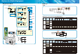
(3) Bipolar Transistors for Adapter
Bipolar Transistors [V
CBO
=700V/800V Series (AC Adapter)]
Type No. Package
Absolute maximum ratings/Ta=25˚C
Electrical characteristics/Ta=25˚C
Input
Voltage
[V]
AC Adapter
Circuits
[W]
V
CBO
[V]
V
CEO
[V]
I
C
[A]
h
FE
V
CE
(sat) [V]
I
C
[A]
min max
I
C
[mA]
I
B
[mA]
max
2SC5823 TP 700 400 1.5 0.1 20 50 700 140 0.8 100/220 3/6
2SC5808 TP 700 400 2.5 0.3 20 50 1200 240 0.8 100/220 4/8
❈
TT2240NMP NMP 700 400 1.0 0.1 15 30 500 100 0.8 100/220 1.5/3
2SC6065-V NMP 700 400 1.5 0.1 20 50 700 140 0.8 100/220 3/6
2SC6083 SPA 700 350 1.0 0.1 100 200 500 100 0.8 100 1.5
2SC6083A SPA 700 400 1.0 0.1 50 100 500 100 0.8 100/220 1.5/3
❈
2SC6146 SPA 800 350 1.0 0.1 100 200 500 100 0.8 220 3
CPH3249 CPH3 700 350 1.0 0.1 100 200 500 100 0.8 100/220 1.5/3
CPH3249A CPH3 700 400 1.0 0.1 50 100 500 100 0.8 100/220 1.5/3
[Bipolar Transistor Use Example]
Control IC
Output
+5.6 to 5.8V/600 to 700mA
-
R
BE
Starting
resistor
Main
S/W Tr
AC Input
Thermistor
❈
: Development
◆
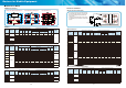
Lineup
Set Spec PFC
SPS for
AV Processor
SPS for
BL Inverter
2nd Rectifi er
Panel Size
[inch]
P
OUT
[W]
V
OUT
[V]
FRD(1) MOSFET(1) MOSFET(2) MOSFET(3)
SBD(1)
SBD(2)/FRD(2)
up to 21 70 5/12 - -
2SK4086LS
(also used for
BL power supply)
-
SBT80-06J(1)
SBT100-16JS(1)
26 to 32 150
5 to 12
24
❈
RD1006LS 2SK4085LS 2SK4098LS 2SK4096LS×2
SBT100-16JS(1)
SBT100-16JS(2)
37 to 42 250
5 to 12
24
❈
RD0506LS 2SK4124×2 2SK4098LS 2SK4097LS×2
SBT100-16JS(1)
SBT150-10JS(2)
at least 42 350
5 to 12
24/60
❈
RD1006LS 2SK4124×3 2SK4101LS 2SK4084LS×2
SBT100-16JS(2)
SBT150-10JS(1)
RD2004LS(2)
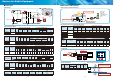
[Power supply block]
• Circuit
For under 21inch, used for both AV processor (main power supply) and BL inverter power supply.
For larger than 26inch, 2-power supply system is usually used (one is for BL inverter use, and the other is for AV processor use).
• Secondary-side diode voltage
In case of fl yback circuit, diode voltage should be 100V and above for 12V output (when PFC output is 380V).
In case of half-bridge circuit, diode voltage should be 100V and above for 24V output (when PFC output is 380V).
■
LCD TV
ACIN
PFC
Control
PFC FRD(1)
PFC Circuit
PFC
MOSFET(1)
Main SW
MOSFET(2)
Main SW
MOSFET(2)
Pulse IN
DC
Output
V
CC
SBD(2)/FRD(2)
SBD(2)/FRD(2)
Main SW
MOSFET(3)
DC
Output
SBD(1)
Main Control
SBD(1)
Half-Bridge Power Supply
Flyback Power Supply
* For under 21inch, also used for
BL inverter power supply.
❈
: Development
Recommended Devices by LCD-TV Panel Size
(1) When BL inverter is half-bridge circuit, and AV output is fl yback circuit