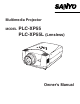
Multimedia Projector MODEL PLC-XP55 PLC-XP55L (Lensless) Owner’s Manual
TO THE OWNER Before operating this projector, read this manual thoroughly and operate the projector properly. This projector provides many convenient features and functions. Operating the projector properly enables you to manage those features and maintains it in better condition for a considerable time. Improper operation may result in not only shortening the product-life, but also malfunctions, fire hazard, or other accidents.
SAFETY INSTRUCTIONS All the safety and operating instructions should be read before the product is operated. Read all of the instructions given here and retain them for later use. Unplug this projector from AC power supply before cleaning. Do not use liquid or aerosol cleaners. Use a damp cloth for cleaning. This projector should be operated only from the type of power source indicated on the marking label.
COMPLIANCES Federal Communication Commission Notice Note : This equipment has been tested and found to comply with the limits for a Class B digital device, pursuant to part 15 of the FCC Rules. These limits are designed to provide reasonable protection against harmful interference in a residential installation. This equipment generates, uses and can radiate radio frequency energy and, if not installed and used in accordance with the instructions, may cause harmful interference to radio communications.
TABLE OF CONTENTS FEATURES AND DESIGN PREPARATION NAME OF EACH PART OF PROJECTOR SETTING-UP PROJECTOR CONNECTING AC POWER CORD POSITIONING PROJECTOR ADJUSTABLE FEET INSTALLING PROJECTOR IN PROPER POSITION MOVING PROJECTOR 6 7 7 8 8 9 10 10 11 CONNECTING PROJECTOR 12 TERMINALS OF PROJECTOR CONNECTING TO COMPUTER CONNECTING TO VIDEO EQUIPMENT 12 13 14 COMPUTER INPUT SELECTING INPUT SOURCE SELECTING COMPUTER SYSTEM PC ADJUSTMENT AUTO PC ADJUSTMENT MANUAL PC ADJUSTMENT PICTURE IMAGE SELECT IMAGE LEVEL SE
FEATURES AND DESIGN This Multimedia Projector is designed with most advanced technology for portability, durability, and ease of use. This projector utilizes built-in multimedia features, a palette of 16.77 million colors, and matrix liquid crystal display (LCD) technology. ◆ Compact Design This projector is extremely compact in size and weight. It is designed to carry and work anywhere you wish to use.
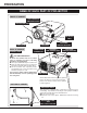
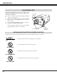
PREPARATION NAME OF EACH PART OF PROJECTOR FRONT OF CABINET TOP CONTROLS AND INDICATORS PROJECTION LENS AIR INTAKE VENT LENS COVER BACK OF CABINET EXHAUST VENT SPEAKERS POWER CORD CONNECTOR INFRARED REMOTE RECEIVER TERMINALS AND CONNECTORS INFRARED REMOTE RECEIVER HOT AIR EXHAUSTED ! Air blown from exhaust vent is hot. When using or installing a projector, following precautions should be taken. ● Do not put a flammable object near this vent. ● Keep rear grills at least 3.
PREPARATION SETTING-UP PROJECTOR CONNECTING AC POWER CORD This projector uses nominal input voltages of 100-120 V or 200-240 V AC. This projector automatically selects correct input voltage. It is designed to work with single-phase power systems having a grounded neutral conductor. To reduce risk of electrical shock, do not plug into any other type of power system. Consult your authorized dealer or service station if you are not sure of type of power supply being in use.
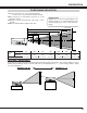
PREPARATION POSITIONING PROJECTOR NOTE: The figures below are only for Model PLC-XP55. Projection lens is not provided with Model PLC-XP55L. ● This projector is designed to project on a flat projection surface. ● Projector can be focused from 4.6’ (1.4m) ~ 48.3’ (14.7m). ● Refer to figure below to adjust screen size. ROOM LIGHT Brightness in room has a great influence on picture quality. It is recommended to limit ambient lighting in order to provide best image. 48.3’(14.7m) 36.1’(11.0m) 24.0’(7.
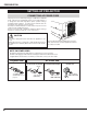
PREPARATION ADJUSTABLE FEET Picture tilt and projection angle can be adjusted by rotating ADJUSTABLE FEET. Projection angle can be adjusted to 10.5 degrees. 1 Lift front of a projector and pull FEET LOCK LATCHES on both sides of a projector. 2 Release FEET LOCK LATCHES to lock ADJUSTABLE FEET and rotate ADJUSTABLE FEET to fine tune position and tilt. 3 To shorten ADJUSTABLE FEET, lift front of a projector and pull and undo FEET LOCK LATCHES.
PREPARATION MOVING PROJECTOR Use Carry Handle when moving a Projector. When moving a projector, replace lens cover and retract feet to prevent damage to lens and cabinet. When this projector is not in use for an extended period, put it into case (dust cover) supplied with this projector. CAUTION IN CARRYING OR TRANSPORTING A PROJECTOR ● Do not drop or bump a projector, otherwise damages or malfunctions may result. ● When carrying a projector, use a suitable carrying case.
CONNECTING PROJECTOR TERMINALS OF PROJECTOR This projector has input and output terminals on its back for connecting computers and video equipment. Refer to figures on pages 12 to 14 and connect properly. COMPUTER AUDIO INPUT 1/AUDIO MONITOR OUTPUT JACK This terminal is switchable and can be used as computer audio input 1 or audio monitor output (variable). Set the terminal up as either Computer audio input 1 or Audio Monitor output properly before using this terminal. Refer to P13, P23.
CONNECTING PROJECTOR CONNECTING TO COMPUTER Cables used for connection (✽ = Cable or adapter is not supplied with this projector.) • VGA Cable (HDB 15 pin) • Control Cable for PS2 Port ✽, or ADB Port ✽ • USB Cable • DVI-Digital Cable (for Single Link T.M.D.S.
CONNECTING PROJECTOR CONNECTING TO VIDEO EQUIPMENT Cables used for connection (✽ = Cable is not supplied with this projector.) • Video Cable (RCA x 1 or RCA x 3) ✽ • BNC Cable ✽ • S-VIDEO Cable ✽ • Audio Cable (RCA x 2) ✽ • Audio Cable {Mini Plug (stereo)} ✽ • Scart Cable ✽ Video Source (example) Video Cassette Recorder Component video output equipment. (such as DVD player or high-definition TV source.
BEFORE OPERATION OPERATION OF REMOTE CONTROL LASER POINTER (Drag ON) INDICATOR Left Side POWER ON-OFF BUTTON ON Lights red while laser beam is emitted from Laser Light Window. Lights green when drag ON position. (P41) AUTO PC ON-OFF D.ZOOM FREEZE NO SHOW LOCK ALL OFF MUTE BUTTON Used to mute sound. (P22) DRAG ON/OFF BUTTON ALL-OFF SWITCH When using Remote Control Unit, turn this switch to “ON.” And turn it to “ALL OFF” when it is not used.
BEFORE OPERATION NO SHOW BUTTON D.ZOOM BUTTON Used to select DIGITAL ZOOM +/– mode and resize image. (P29) AUTO PC ON-OFF D.ZOOM FREEZE NO SHOW SELECT BUTTON LOCK Used to execute the selected item, or to expand or compress image in DIGITAL ZOOM +/- mode. (P29) Used to turn picture into black image. (P22) MUTE IMAGE VOLUME- SELECT VOLUME+ KEYSTONE MENU FREEZE BUTTON Used to freeze picture. (P22) MENU BUTTON INPUT 1 BUTTON P-TIMER BUTTON P-TIMER INPUT 1 16.4’ (5 m) INPUT 2 BUTTON ZOOM COLOR.
BEFORE OPERATION TOP CONTROLS AND INDICATORS This projector has CONTROL BUTTONS (TOP CONTROLS) and INDICATORS on its top. LAMP REPLACE INDICATOR WARNING TEMP. INDICATOR READY INDICATOR LAMP INDICATOR Turns to yellow when life of projection lamp draws to an end. (P44) Flashes red when internal projector temperature is too high. (P42) Lights green when a projector is ready to be turned on. And it flashes green in Power Management mode. (P39) Becomes dim when a projector is turned on.
BEFORE OPERATION OPERATING ON-SCREEN MENU HOW TO OPERATE ON-SCREEN MENU You can control and adjust this projector through ON-SCREEN MENU. Refer to following pages to operate each adjustment on ON-SCREEN MENU. REMOTE CONTROL UNIT AUTO PC ON-OFF 1 DISPLAY MENU Press MENU button to display ON-SCREEN MENU. POINT BUTTONS D.ZOOM FREEZE NO SHOW ✽ Pointer is icon on ON-SCREEN MENU to select item. See figures on section "FLOW OF ON-SCREEN MENU OPERATION" below.
BEFORE OPERATION MENU BAR FOR PC SOURCE Press MENU BUTTON while connecting to PC input source. GUIDE WINDOW PC SYSTEM MENU Shows selected item of ONSCREEN MENU. Used to select computer system. (Refer to P23, 24) IMAGE SELECT MENU SCREEN MENU SETTING MENU Used to select image level among Standard, Real and Image 1 ~ 4. (Refer to P28) Used to adjust size of image. [Normal / True / Wide / Digital zoom +/–] (Refer to P29) Used to change settings of projector or reset Lamp Replace Counter.
BASIC OPERATION TURNING ON / OFF PROJECTOR TURNING ON PROJECTOR 1 Complete peripheral connections (with Computer, VCR, etc.) before turning on projector. (Refer to "CONNECTING TO PROJECTOR" on pages 12~14 for connecting that equipment.) 2 Connect a projector's AC Power Cord into an AC outlet. LAMP Indicator lights RED, and READY Indicator lights GREEN.
BASIC OPERATION ADJUSTING SCREEN ZOOM ADJUSTMENT 1 Press ZOOM button on Top Control or ZOOM ▲/▼ button on Remote Control Unit. Message “Zoom” is displayed. 2 Press ZOOM ▲ button or POINT UP button to make image larger, and press ZOOM ▼ button or POINT DOWN button to make image smaller. Message disappears after 4 seconds. FOCUS ADJUSTMENT 1 Press FOCUS button on Top Control or FOCUS ▲/▼ button on Remote Control Unit. Message “Focus” is displayed.
BASIC OPERATION PICTURE FREEZE FUNCTION Press FREEZE button on Remote Control Unit to freeze picture on-screen. To cancel FREEZE function, press FREEZE button again or press any other button. NO SHOW FUNCTION Press NO SHOW button on Remote Control Unit to black out image. To restore to normal, press NO SHOW button again or press any other button. Message disappears after 4 seconds. P-TIMER FUNCTION Press P-TIMER button on Remote Control unit.
COMPUTER INPUT SELECTING INPUT SOURCE INPUT button DIRECT OPERATION ✽ Select INPUT source by pressing INPUT button on Top Control. Select INPUT source by pressing INPUT 1, INPUT 2 or INPUT 3 button on Remote Control Unit. If projector cannot reproduce proper image, select correct input source through MENU OPERATION (see below). Input 1 Input 2 Input 3 NOTE ● Input 1 terminal is switchable and can be used as computer input or monitor output.
COMPUTER INPUT WHEN SELECT INPUT 2 (5 BNC INPUT JACKS ) When connect a computer output [5 BNC Type (Green, Blue, Red, Horiz. Sync and Vert. Sync.)] from a computer to G, B, R, H/HV and V jacks. 1 Press MENU button and ON-SCREEN MENU will appear. Press POINT LEFT/RIGHT button to move a red frame pointer to INPUT Menu icon. 2 Press POINT UP/DOWN button to move a red arrow pointer to Input 2 and then press SELECT button. Source Select Menu will appear.
COMPUTER INPUT PC ADJUSTMENT AUTO PC ADJUSTMENT Auto PC Adjustment function is provided to automatically adjust Fine sync, Total dots and Picture Position to conform to your computer. Auto PC Adjustment function can be operated as follows. Auto PC Adj. 1 Press MENU button and ON-SCREEN MENU will appear. Press POINT LEFT/RIGHT button to move a red frame pointer to PC ADJUST Menu icon. 2 Press POINT UP/DOWN button to move a red frame pointer to AUTO PC Adj. icon and then press SELECT button.
COMPUTER INPUT MANUAL PC ADJUSTMENT This projector can automatically tune to display signals from most personal computers currently distributed. However, some computers employ special signal formats which are different from standard ones and may not be tuned by Multi-Scan system of this projector. If this happens, projector cannot reproduce a proper image and image may be recognized as a flickering picture, a non-synchronized picture, a non-centered picture or a skewed picture.
COMPUTER INPUT Press SELECT button at Display area icon and Display area dialog box appears. Display area Selects area displayed with this projector. Select resolution at Display area dialog box. Display area Display area H Adjustment of horizontal area displayed with this projector. Press POINT LEFT/RIGHT button(s) to decrease/increase value and then press SELECT button. Display area V Adjustment of vertical area displayed with this projector.
COMPUTER INPUT PICTURE IMAGE SELECT IMAGE LEVEL SELECT (DIRECT) Select image level among Standard, Real, Image 1, Image 2, Image 3 and Image 4 by pressing IMAGE button on Top Control or on Remote Control Unit. IMAGE button Standard Real Standard Normal picture level preset on this projector. Image 1 Real Picture level with improved halftone for graphics. Image 2 IMAGE 1~4 User preset picture adjustment in IMAGE ADJUST Menu (P36).
COMPUTER INPUT PICTURE SCREEN ADJUSTMENT This projector has a picture screen resize function, which enables you to display desirable image size. 1 Press MENU button and ON-SCREEN MENU will appear. Press POINT LEFT/RIGHT button(s) to move a red frame pointer to SCREEN Menu icon. 2 Press POINT UP/DOWN button and move a red frame pointer to function that you want to select and then press SELECT button. SCREEN MENU SCREEN Menu icon Move red frame to function and press SELECT button.
VIDEO INPUT SELECTING INPUT SOURCE WHEN SELECT INPUT 2 (5 BNC INPUT JACKS ) When connecting to those equipment, select a type of Video source in SOURCE SELECT Menu. 1 INPUT MENU Press MENU button and ON-SCREEN MENU will appear. Press POINT LEFT/RIGHT button to move a red frame pointer to INPUT Menu icon. 2 Press POINT UP/DOWN button to move a red arrow pointer to Input 2 and then press SELECT button. Source Select Menu will appear.
VIDEO INPUT SELECTING VIDEO SYSTEM 1 Press MENU button and ON-SCREEN MENU will appear. Press POINT LEFT/RIGHT buttons to move a red frame pointer to AV SYSTEM Menu icon. 2 Press POINT UP/DOWN button to move a red arrow pointer to system that you want to select and then press SELECT button. VIDEO JACK OR S-VIDEO JACK Auto Projector automatically detects incoming Video system, and adjusts itself to optimize its performance. When Video System is PAL-M or PAL-N, select system manually first.
VIDEO INPUT PICTURE IMAGE SELECT IMAGE LEVEL SELECT (DIRECT) Select image level among Standard, Cinema, Image 1, Image 2, Image 3 and Image 4 by pressing IMAGE button on Top Control or on Remote Control Unit. IMAGE button Standard Cinema Standard Normal picture level preset on this projector. Image 1 Cinema Picture level adjusted for picture with fine tone. Image 2 IMAGE 1~4 User preset picture adjustment in IMAGE ADJUST Menu (P36).
VIDEO INPUT PICTURE SCREEN ADJUSTMENT This projector has a picture screen resize function, which enables you to display desirable image size. 1 Press MENU button and ON-SCREEN MENU will appear. Press POINT LEFT/RIGHT button(s) to move a red frame pointer to SCREEN Menu icon. 2 Press POINT UP/DOWN button and move a red frame pointer to function that you want to select and then press SELECT button. Normal Provides image at a normal video aspect ratio of 4 : 3.
PICTURE IMAGE PICTURE IMAGE ADJUSTMENTS 1 Press MENU button and ON-SCREEN MENU will appear. Press POINT LEFT/RIGHT buttons to move a red frame pointer to IMAGE ADJUST Menu icon. 2 Press POINT UP/DOWN button to move a red frame pointer to item that you want to adjust and then press SELECT button. Level of each item is displayed. Adjust each level by pressing POINT LEFT/RIGHT button(s). IMAGE ADJUST MENU IMAGE ADJUST Menu icon Move a red frame pointer to item to be selected and then press SELECT button.
PICTURE IMAGE 4 To move the red frame pointer to "MENU", and then press the SELECT button. The message "OK"? is displayed. Move the pointer to [Yes] and then press SELECT button. The COLOR MANAGEMENT menu will be exited and the display will return to the IMAGE ADJUST menu. (At this time, the image will stop being paused and normal projection will resume.) After changing the COLOR MANAGEMENT settings, use the IMAGE ADJUST menu to store the changed settings.
PICTURE IMAGE Color temp. Press either POINT LEFT button or POINT RIGHT button to Color temp. level that you want to select. (XLow, Low, Mid or High) White balance (Red) Press POINT LEFT button to lighten red tone and POINT RIGHT button to deeper tone. (From 0 to 63.) White balance (Green) Press POINT LEFT button to lighten green tone and POINT RIGHT button to deeper tone. (From 0 to 63.) Press SELECT button at this icon to display other items.
SETTING SETTING MENU 1 Press MENU button and ON-SCREEN MENU will appear. Press POINT LEFT/RIGHT button(s) to move a red-frame pointer to SETTING icon. 2 Press POINT DOWN button to move a red-frame pointer to item that you want to set and then press SELECT button. Setting dialog box appears. Language Language used in ON-SCREEN MENU is selectable from among English, German, French, Italian, Spanish, Portuguese, Dutch, Swedish, Russian, Chinese, Korean and Japanese.
SETTING Anamorphic When this function is “On,” the screen image is forcibly changed to a 4:3 image, even if the input signal is HDTV. Blue back When this function is “On,” this projector will produce a blue image instead of the video noise on the screen when any input source is unplugged or turned off. Display This function decides whether to display On-Screen Displays. On ··· shows all the On-Screen Displays.
SETTING Power management This projector is equipped with a power management function. When the input signal is interrupted and any button is not pressed for 30 seconds or more, the power management function operates in order to reduce power consumption and conserve lamp operating time. The factory default settings for power management are "Ready" and "5 Min".
SETTING USB This Projector is equipped with USB port for interactive operation between a projector and computer. Set mode following steps below. Wireless Mouse mode Select " this projector. " when controlling a computer with Remote Control of Projector mode Select " " when controlling a projector with computer. NOTE: This is provided not for basic operation but for future use. Key lock This function locks the operation of the projector's control panel and the remote control.
APPENDIX OPERATING WIRELESS MOUSE Wireless Remote Control Unit is not only able to operate this projector but also function as a wireless mouse for most Personal Computers. POINT button, drag ON/OFF button and two CLICK buttons are used for wireless mouse operation. This Wireless Mouse function is available only when PC mouse pointer is displayed on a projected screen.
APPENDIX MAINTENANCE WARNING TEMP. INDICATOR The Warning Temp. Indicator flashes red to let you know the internal temperature of the projector exceeds the normal level. If the temperature goes up further, the projector will be turned off automatically and the Ready indicator will go out. (The Warning Temp. Indicator continues flashing.
APPENDIX AIR FILTER CARE AND CLEANING Air Filter prevents dust from accumulating on surface of Projection Lens and Projection Mirror. Should Air Filter become clogged with dust particles, it will reduce Cooling Fans’ effectiveness and may result in internal heat build up and adversely affect life of a projector. Clean Air Filter following steps below: 1 Turn off a projector, and disconnect AC power cord from AC outlet.
APPENDIX LAMP REPLACEMENT LAMP REPLACE When the life of the Projection Lamp of this projector draws to an end, the LAMP REPLACE indicator lights yellow. If this indicator lights yellow, replace the projection lamp with a new one promptly. TOP CONTROL This indicator lights yellow when the life of the projection lamp draws to an end. Replace the Projection Lamp with a new one promptly. CAUTION Allow a projector to cool, for at least 45 minutes before you open Lamp Cover.
APPENDIX LAMP REPLACE COUNTER Be sure to reset the Lamp Replace Counter after the Lamp Assembly is replaced. When the Lamp Replace Counter is reset, the LAMP REPLACE Indicator stops lighting. 1 Turn projector on, press MENU button and ON-SCREEN MENU will appear. Press POINT LEFT/RIGHT button(s) to move a red frame pointer to SETTING Menu icon (refer to page 40). 2 Press POINT UP/DOWN button to move a red frame pointer to “Lamp counter reset” and then press SELECT button.
APPENDIX TROUBLESHOOTING Before calling your dealer or service center for assistance, check matters below once again. 1. Make sure you have connected a projector to your computer or video equipment as described in section "CONNECTING PROJECTOR" on pages 12 ~ 14. 2. Check cable connection. Verify that all computer, video and power cord are properly connected. 3. Verify that all power is switched on. 4. If a projector still does not produce an image, re-start your computer. 5.
APPENDIX Problem: Try these Solutions Remote Control Unit does not work. ● ● ● ● Wireless Mouse function does not work. ● Check cable connection between a projector and your computer. ● Check mouse setting on your computer. ● Turn a projector on before turning on a computer. Check batteries. Check ALL-OFF switch on Remote Control Unit is set to “ON”. Make sure nothing is between Infrared Remote Receiver and Remote Control Unit.
APPENDIX INDICATORS AND PROJECTOR CONDITION Check the Indicators for projector condition. Indicators LAMP REPLACE yellow WARNING TEMP. red READY LAMP green red Projector Condition The projector is OFF. (The AC Power Cord is unplugged.) ✽ The projector is READY to be turned on with the POWER ONOFF button. ✽ The projector is operating normally. ✽ The Warning Temp. Indicator flashes red to let you know the internal temperature of the projector exceeds the normal level.
APPENDIX COMPATIBLE COMPUTER SPECIFICATIONS Basically this projector can accept a signal from all computers with V, H-Frequency mentioned below and less than 180 MHz of Dot Clock.
APPENDIX MENU TREE Input Input Input 1 SYSTEM 1) RGB RGB( Scart) RGB(PC Digital) SYSTEM 1) SYSTEM 2) RGB( AV HDCP ) Monitor out Input 2 Input 3 Video SYSTEM 3) Y, Pb/Cb, Pr/Cr SYSTEM 4) RGB SYSTEM 1) Video SYSTEM 3) Y, Pb/Cb, Pr/Cr SYSTEM 4) S-Video SYSTEM 3) PC source Screen Video source Normal True System Wide System Mode 1 2) 1) Digital zoom + Mode 2 Digital zoom - VGA 1 SVGA 1 XGA 1 PC adjust System Auto 3) PAL Auto PC Adj.
APPENDIX System Setting Language English Image adjust Contrast 0 - 63 German Brightness 0 - 63 French Color 0 - 63 Italian Tint 0 - 63 Spanish Color management 0 - 63 Portuguese Auto picture control Off/L1/L2 Dutch Color temp.
APPENDIX TECHNICAL SPECIFICATIONS Projector Type Dimensions (W x H x D) Net Weight LCD Panel System Panel Resolution Number of Pixels Color System High Definition TV Signal Scanning Frequency Projection Lens Throw distance Motorized Lens Shift Multi-media Projector 12.6" x 6.6" x 18.5" (319 mm x 168 mm x 470 mm) 20.3 lbs (9.2 kg) PLC-XP55, 17.4 lbs (7.9 kg) PLC-XP55L 1.3" TFT Active Matrix type, 3 panels 1024 x 768 dots 2,359,296 (1024 x 768 x 3 panels) PAL, SECAM, NTSC, NTSC4.
APPENDIX CONFIGURATIONS OF TERMINALS COMPUTER INPUT-1 and MONITOR OUT TERMINALS (ANALOG) Terminal : HDB15-PIN Pin Configuration 4 5 10 15 2 3 9 14 8 13 1 7 12 6 11 1 2 3 4 5 6 7 8 Red Input Green Input Blue Input Sense 2 Ground (Horiz.sync.) Ground (Red) Ground (Green) Ground (Blue) 9 10 11 12 13 14 15 +5V Power Ground (Vert.sync.) Sense 0 DDC Data Horiz. sync. Vert. sync.
APPENDIX OPTIONAL PARTS The parts listed below are optionally supplied. When ordering those parts, give the name and Type No. to the sales dealer. ● Control Cable (PS2 Port) Type No. : POA-MCPS2 ● Control Cable (ADB Port) Type No. : POA-MCMAC ● MAC Adapter Type No. : POA-MACAP ● DVI Cable Type No. : KA-DV20 ● HDB 15 pin-SCART 21 pin Cable Type No. : POA-CA-SCART ● Long Zoom Lens Type No. : LNS-T31A ● Ultra Long Zoom Lens Type No. : LNS-T32 ● Short Zoom Lens Type No.
APPENDIX 55
Printed in Japan Part No. 610 306 0675 (1AA6P1P3948-- MR3A) SANYO Electric Co.