INSTRUCTION MANUAL Blood Bank Refrigerator MBR-704GR MBR-704G MBR-704GR
Note: 1. No part of this manual may be reproduced in any form without the expressed written permission of SANYO. 2. The contents of this manual are subject to change without notice. 3. Please contact SANYO if any point in this manual is unclear or if there are any inaccuracies. SANYO Electric Biomedical Co., Ltd. All rights reserved. Printed in Japan. CONTENTS PRECAUTIONS FOR SAFE OPERATION P. 2 CAUTIONS FOR USAGE P. 6 ENVIRONMENTAL CONDITIONS P. 6 REFRIGERATOR COMPONENTS P. 7 INSTALLATION P.
It is imperative that the user complies with this manual as it contains important safety advice. Items and procedures are described so that you can use this unit correctly and safely. If the precautions advised are followed, this will prevent possible injury to the user and any other person. Precautions are illustrated in the following way: WARNING Failure to observe WARNING signs could result in a hazard to personnel possibly resulting in serious injury or death.
PRECAUTIONS FOR SAFE OPERATION WARNING Do not use the unit outdoors. Current leakage or electric shock may result if the unit is exposed to rain water. Only qualified engineers or service personnel should install the unit. unqualified personnel may cause electric shock or fire. The installation by Install the unit on a sturdy floor. If the floor is not strong enough or the installation site is not adequate, this may result in injury from the unit falling or tipping over.
PRECAUTIONS FOR SAFE OPERATION WARNING Disconnect the power supply to the unit prior to any repair or maintenance of the unit in order to prevent electric shock or injury. Ensure you do not inhale or consume medication or aerosols from around the unit at the time of maintenance. These may be harmful to your health. Never splash water directly onto the unit as this may cause electric shock or short circuit. Never disassemble, repair, or modify the unit yourself.
PRECAUTIONS FOR SAFE OPERATION CAUTION Fix the shelves securely. Incomplete installation may cause injury or damage. When removing the plug from the power supply outlet, grip the power supply plug, not the cord. Pulling the cord may result in electric shock or fire by short circuit. Never damage or break the power supply plug or cord. Do not use the supply plug if its cord is loose. This may cause fire or electric shock.
CAUTIONS FOR USAGE 1. If the unit is unplugged or the power to the unit is interrupted, do not restart the unit for at least 5 minutes. This protects the compressor. 2. This inner cabinet is refrigerated by the forced circulation of cooled air inside the chamber. Ensure that the intake and exhaust vents are not blocked. Adequate space should be provided between the items inside the unit to allow air circulation. 3.
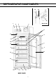
REFRIGERATOR COMPONENTS 21 20 22 1 2 9 3 11 18 6 8 10 5 16 7 4 15 12 17 14 13 19 23 MBR-704GR 7
REFRIGERATOR COMPONENTS 1. Front cover: Open this cover when connecting the remote alarm or replacing glow starter for fluorescent lamp. 2. Control panel: Refer to page 10. Panel can be opened when upper right corner of the lower part cover is pushed. 3. Automatic temperature recorder: A 7-day type recorder is provided. For proper usage of the recorder, see the instruction manual enclosed with the unit. 4. Access port: This port allows temperature measurement cables to enter the chamber from outside.
REFRIGERATOR COMPONENTS Inside of front cover 1 2 ON OFF 3 1. Glow starter (with cover): This is for the fluorescent light. It is recommended that the glow starter is also replaced when the fluorescent light is replaced. Refer to page 19. 2. Remote alarm terminal: This is used to connect the unit to an exterior alarm to notify users of any malfunction. Refer to page 17. 3. Battery switch: Switch for battery used for power failure alarm. Always keep "ON".
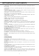
REFRIGERATOR COMPONENTS Control panel and keypad 7 1. Buzzer stop key (BUZZER): 8 9 10 1 2 3 11 4 5 6 To silence the audible alarm, press this key. 2. Temperature display key (UPPER/LOWER): By pressing this key, the displayed temperature is changed; upper monitor bottle temperature, lower monitor bottle temperature, and average temperature of upper and lower monitor bottles are displayed in sequence. 3.
INSTALLATION Installation site To operate this unit properly and to obtain maximum performance, install the unit in a location with the following conditions: 1. A location not subjected to direct sunlight Installation in a location subjected to direct sunlight may lead to inadequate cooling. 2. A location with adequate ventilation Leave at least 10 cm around the unit for ventilation. Poor ventilation will result in a reduction of the refrigeration capacity. 3.
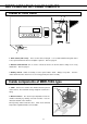
INSTALLATION Installation 1. Remove the packaging materials and tapes Remove all transportation packaging materials and tapes. Open the doors and ventilate the unit. If the outside panels are dirty, clean them with a neutral detergent and wipe off with a soft cloth washed in clean water. 2. Adjust the leveling feet Extend the leveling feet by rotating them as shown in the figure until they make contact with the floor. Ensure the unit is level. 3.
INSTALLATION Preparation of monitor bottle Prior to the operation of the unit, fill the monitor bottles (upper and lower) with 10% glycerol (or other solution such as ethylene glycol) using the following procedure: 3 4 4 2 1. Remove the top and bottom drawer (or shelf). 2. Remove the monitor bottle cover as shown in the figure. 3. Detach the sensor from the monitor bottle. 4. Pull up the bottle to take it out. 5.
START-UP OF UNIT Follow the procedures for the initial and consequent operations of the unit. 1. Connect the power cord to the dedicated outlet with appropriate rating. 2. On start-up, the alarm buzzer sometimes operates. In this case, stop the buzzer by pressing the buzzer stop key (BUZZER). The alarm will operate until the temperature monitor bottle sensor goes into the range of 4 oC±2 oC. See Table 2 in page 17. 3.
OPERATING INSTRUCTIONS Control panel Temperature display The unit is set at the factory to obtain the proper temperature automatically (4 oC±1 oC). The high temperature alarm is preset at 6 oC. The low temperature alarm is preset at 2 oC. Table 1. Operation 1 Plug-in, Power ON 2 Press 3 Press 4 Press UPPER LOWER UPPER LOWER UPPER key. key. key.
OPERATING INSTRUCTIONS Temperature sensor calibration procedure The temperature sensors are attached to the monitor bottles. Follow the following instructions for proper calibration (0 adjustments). 1. Remove the monitor bottle cover as shown in the figure. 2. Remove the sensor to be calibrated from the monitor bottle. Please note that refrigerator also has a sensor for the temperature recorder in the left side of the upper monitor bottle. 3.
ALARMS & SAFETY FUNCTIONS This unit has the alarms and safety functions shown in Table 2, and also self diagnostic functions. Table 2 Alarms and safety functions Alarm & Safety High temperature alarm Low temperature alarm Over-temperature protection Power failure alarm Situation If the upper or lower temperature o sensor senses a temperature ≧ 6 C. If the upper or lower temperature o sensor senses a temperature ≦ 2 C. If the high-temperature thermostat sensor senses a temperature o approximately > 10 C.
ROUTINE MAINTENANCE WARNING Always disconnect the power supply to the unit prior to any repair or maintenance of the unit in order to prevent electric shock or injury. Ensure you do not inhale or consume medication or aerosols from around the unit at the time of maintenance. These may be harmful to your health. CAUTION Always wear dry gloves to protect hands at the time of maintenance. Failure to wear gloves may result in injury from edges and corners. Cleaning of cabinet 1. Clean the unit once a month.
ROUTINE MAINTENANCE Replacement of fluorescent lamp The fluorescent lamp is placed horizontally in the upper front of the chamber. Follow the procedure below to replace the lamp. 1. Turn off the fluorescent light switch and disconnect the power supply plug. 2. Hold the cover of the light and pull downward with lead wire to remove the lamp from stopper. (Fig. 1) 3. Remove the water-proof rubber on the left. (Fig. 2) 4. Remove the socket on the left. (Fig. 2) 5.
TROUBLE SHOOTING If the unit malfunctions, check out the following before calling for service. If nothing operates even when switched on 1. The power is failed. 2. The circuit breaker is inactivated. 3. The unit is not connected to the power supply. The alarm device is activated 1. The temperature in the unit does not match the set value. 2. The door was kept opened for a long time. 3. The high temperature materials were put in the unit.
SPECIFICATIONS Name Blood Bank Refrigerator Model MBR-704G MBR-704GR External dimensions W770 x D830 x H1955 (mm) Internal dimensions W650 x D697 x H1500 (mm) Effective capacity 625 L 617 L Exterior Painted steel Interior Painted steel Door Steel plate with double layer pair glass, automatic closing mechanism Insulation Rigid polyurethane foamed-in place Shelf Hard steel wire on polyethylene coating 6 pcs. ----- Drawer ----- Stainless steel, Handle with card holder 6 pcs.
CAUTION Please fill in this form before servicing. Hand over this form to the service engineer to keep for his and your safety. Safety check sheet 1. Refrigerator contents : Risk of infection: Risk of toxicity: Risk from radioactive sources: □Yes □No □Yes □Yes □Yes □No □No □No (List all potentially hazardous materials that have been stored in this unit.) Notes : 2. Contamination of the unit Unit interior No contamination Decontaminated Contaminated Others: □Yes □No □Yes □Yes □Yes □No □No □No 3.
7FB6P101294003 (5 April 2005) Recycled paper SANYO Electric Biomedical Co., Ltd.