INSTRUCTION MANUAL Pharmaceutical Refrigerator MPR-513R MPR-513 MPR-513R MPR-1013 MPR-1013R MPR-1013R
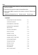
Note: 1. No part of this manual may be reproduced in any form without the expressed written permission of SANYO. 2. The contents of this manual are subject to change without notice. 3. Please contact SANYO if any point in this manual is unclear or if there are any inaccuracies. SANYO Electric Biomedical Co., Ltd. All rights reserved. Printed in Japan. CONTENTS PRECAUTIONS FOR SAFE OPERATION P. 2 CAUTIONS FOR USAGE P. 6 ENVIRONMENTAL CONDITIONS P. 7 REFRIGERATOR COMPONENTS P. 8 INSTALLATION P.
PRECAUTIONS FOR SAFE OPERATION It is imperative that the user complies with this manual as it contains important safety advice. Items and procedures are described so that you can use this unit correctly and safely. If the precautions advised are followed, this will prevent possible injury to the user and any other person. Precautions are illustrated in the following way: WARNING Failure to observe WARNING signs could result in a hazard to personnel possibly resulting in serious injury or death.
PRECAUTIONS FOR SAFE OPERATION WARNING Do not use the unit outdoors. Current leakage or electric shock may result if the unit is exposed to rain water. Only qualified engineers or service personnel should install the unit. unqualified personnel may cause electric shock or fire. The installation by Install the unit on a sturdy floor. If the floor is not strong enough or the installation site is not adequate, this may result in injury from the unit falling or tipping over.
PRECAUTIONS FOR SAFE OPERATION WARNING Do not pull out more than 2 drawers at the same time when storing or taking out of the stocked material. This may cause injury by falling or tipping of the unit if something heavy items are stored. Disconnect the power supply to the unit prior to any repair or maintenance of the unit in order to prevent electric shock or injury. Ensure you do not inhale or consume medication or aerosols from around the unit at the time of maintenance.
PRECAUTIONS FOR SAFE OPERATION CAUTION Fix the shelves securely. Incomplete installation may cause injury or damage. When removing the plug from the power supply outlet, grip the power supply plug, not the cord. Pulling the cord may result in electric shock or fire by short circuit. Never damage or break the power supply plug or cord. Do not use the supply plug if its cord is loose. This may cause fire or electric shock.
CAUTIONS FOR USAGE 1. If the unit is unplugged or the power to the unit is interrupted, do not restart the unit for at least 5 minutes. This protects the compressor. 2. This inner cabinet is refrigerated by forced circulation of cooled air inside the chamber. Ensure that the intake and exhaust air vents are not blocked. 3. Adequate space should be provided between the items inside the unit to allow air circulation. 4. The temperature alarm may be operated at the time of first start-up.
CAUTIONS FOR USAGE Circuit breaker This unit is equipped with a circuit breaker on the back. Make sure to switch ON this breaker before the unit starts to run. Following figures show the circuit breaker position. Circuit breaker When the operation of the unit is stopped by this breaker, contact a dealer or a service station after disconnected the power supply plug. WARNING Never disassemble, repair, or modify the unit yourself.
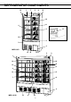
REFRIGERATOR COMPONENTS 14 1 7 2 8 14 10 11 4 5 17 12 6 9 3 MPR-513R 15 16 13 2 8 1 14 14 10 12 11 4 10 5 7 9 3 MPR-1013R 15 6 16 8 13
REFRIGERATOR COMPONENTS 1. Door: Sliding type. The recessed portion on the rail enables the self-closing of the door. The glass is pair construction. 2. Control panel: Panel can be opened when upper right corner of the lower part cover is pushed. Refer to page 10. 3. Space for automatic temperature recorder: An automatic temperature recorder (optional accessory) can be mounted here. See page 13. 4. Access port: This port allows temperature measurement cables to enter the chamber from outside. 5.
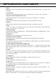
REFRIGERATOR COMPONENTS Control panel and keypad 7 6 5 1 1. Buzzer stop key (BZ): reactivate the alarm. 2 3 To silence the audible alarm, press this key. 4 Press it once again to 2. Set key (SET): Temperature setting mode is initiated by pressing this key. Once the key is pressed, the digit to be changed will flash. Pressing this key again after setting the desired temperature stores the set temperature in the memory. 3.
INSTALLATION Installation site To operate this unit properly and to obtain maximum performance, install the unit in a location with the following conditions: 1. A location not subjected to direct sunlight Installation in a location subjected to direct sunlight may lead to inadequate cooling. 2. A location with adequate ventilation Leave at least 10 cm around the unit for ventilation. Poor ventilation will result in a reduction of the refrigeration capacity. 3.
INSTALLATION Installation 1. Remove the packaging materials and tapes Remove all transportation packaging materials and tapes. Open the doors and ventilate the unit. If the outside panels are dirty, clean them with a neutral detergent and wipe it off with a soft cloth washed in clean water. Leveling foot Fig. 1 2. Adjust the leveling foot Extend the leveling feet by rotating them counterclockwise until they make contact with the floor. See Fig. 1. Ensure the unit is level. 3.
OPTIONAL COMPONENTS Automatic temperature recorder An automatic temperature recorder is available for this refrigerator as an optional accessory. If an automatic temperature recorder is required, contact your Sanyo dealer. For the proper usage of temperature recorder, refer to an instruction manual included with the recorder.
OPTIONAL COMPONENTS Attachment of recorder MTR-G04 WARNING Always disconnect the power supply plug before installing an automatic temperature recorder in order to prevent electric shock or injury. 1. Follow the instruction manual provided with the temperature recorder and attach the recorder to the fixture MPR-S7. shaft screw 2. Open the cover for recorder attachment space by removing the screw. cover Fig. 1 3. Remove the cover by pushing the shaft on both side outward. See Fig. 1. MTR-G04 4.
START-UP OF UNIT Follow the procedures for the initial and consequent operations of the unit. 1. Connect the power cord to the dedicated outlet with appropriate rating. 2. On start-up, the alarm buzzer sometimes operates. alarm stop key (BZ). In this case, stop the buzzer by pressing the 3. Set the chamber temperature to 5oC. 4. Allow the chamber temperature to fall to 5oC. Check the chamber temperature on the temperature indicator. 5. Turn on the fluorescent light switch to check the light.
TEMPERATURE SETTING Chamber temperature Table 1 shows the basic procedure for setting the chamber temperature. Perform key operations in the sequence indicated in the table. The example in the table is based on the assumption that the desired temperature is 4oC. Note: The unit is set at the factory with a chamber temperature of 5oC. Table 1. Chamber set temperature 4oC) Basic operation sequence (Example: Description of operation 1 Turn the power switch ON. 2 Press SET key. 3 Press to 4.
TEMPERATURE SETTING Alarm temperature setting This unit is provided with both high and low temperature alarms. The temperature at which the alarm is activated may be changed. The available set range for high temperature alarm is between +2oC and +14oC and -2oC and -14oC for low temperature alarm against the chamber temperature. Note: The temperature alarm is set at ±5oC of the set temperature at the factory.
ALARMS & SAFETY FUNCTIONS This unit has the alarms and safety functions shown in Table 5, and also self diagnostic functions. Table 5. Alarms and safety functions Alarm & Safety Situation If the chamber temperature deviates o from the set temperature +2 C or up to o +14 C. If the chamber temperature deviates o from the set temperature -2 C or up to o -14 C. If the chamber temperature is lower o than 0 C. When the chamber temp. is higher o than 28 C. (Reset when the chamber o temp.
ALARMS & SAFETY FUNCTIONS Remote alarm terminal WARNING Always disconnect the power supply to the unit prior to connection of alarm equipment to the terminal in order to prevent electric shock or injury. The terminal to which a lead wire of remote alarm is connected is positioned in the box at the rear of the cabinet. The contact capacity is DC30V, 2A.
ROUTINE MAINTENANCE WARNING Always disconnect the power supply to the unit prior to any repair or maintenance of the unit in order to prevent electric shock or injury. Ensure you do not inhale or consume medication or aerosols from around the unit at the time of maintenance. These may be harmful to your health. CAUTION Always wear dry gloves to protect hands at the time of maintenance. Failure to wear gloves may result in injury from edges and corners. Cleaning of cabinet 1. Clean the unit once a month.
ROUTINE MAINTENANCE Clean the evaporating tray once a month following the procedure below. Cleaning of evaporating tray 1. Remove the screws on the bottom of the unit cover and remove the cover. See Fig. 1. Fig. 1 2. For model MPR-513 and MPR-513R, remove the evaporating tray mounting plate by pulling out the clips towards front. Then take out the evaporating tray as shown in Fig. 2 and Fig. 3. Clips Fig. 2 Fig. 3 For MPR-1013 and MPR-1013R, as shown in Fig.
ROUTINE MAINTENANCE Replacement of fluorescent lamp 1. The fluorescent lamp is placed vertically at the center of the frame (MPR1013 and MPR-1013R) and horizontally at the top front of the cabinet (MPR-513 and MPR-513R) MPR-1013 MPR-1013R 2. Turn off the fluorescent lamp switch and disconnect the power supply plug . Fig. 1 3. For MPR-513 and MPR-513R, remove the top shelf, for MPR-1013 and MPR-1013R, remove all shelves in the left side of the cabinet. MPR-513 MPR-513R 4. As shown in Fig. 1 and Fig.
TROUBLESHOOTING If the unit malfunctions, check out the following before calling for service. If nothing operates even when switched on 1. There is a power failure. 2. The circuit breaker is inactivated. 3. The unit is not connected to the power supply. When no key operation is available 1. The key lock is set in OFF (L 0). The alarm device is activated < On start-up > 1. The temperature in the unit does not match set value. < In use > 1. The door was kept opened for a long time. 2.
SPECIFICATIONS Name Model Pharmaceutical Refrigerator MPR-1013 MPR-1013R MPR-513 MPR-513R External dimensions W1800 x D600 x H1790 (mm) W900 x D600 x H1790 (mm) Internal dimensions W1700 x D465 x H1300 (mm) W800 x D465 x H1300 (mm) Effective capacity 1037 L 489 L 1034 L Exterior Painted steel Interior Stainless steel Door 2 pcs.
PERFORMANCE Model MPR-513, MPR-513R Temperature control range +2oC to +14oC Usable ambient temperature -5oC to +35oC Noise level 45dB (A scale) Maximum pressure Rated voltage 1500 kPa AC 110 V AC 115 V AC 220 V AC 220 V AC 230 V AC 240 V Rated frequency 60 Hz 60 Hz 60 Hz 50 Hz 50 Hz 50 Hz Power consumption 245 W 220 W 220 W 205 W 210 W 210 W Model MPR-1013, MPR-1013R Temperature control range +2oC to +14oC Usable ambient temperature -5oC to +35oC Noise level 50 dB (A scal
CAUTION Please fill in this form before servicing. Hand over this form to the service engineer to keep for his and your safety. Safety check sheet 1. Refrigerator contents : Risk of infection: Risk of toxicity: Risk from radioactive sources: □Yes □No □Yes □Yes □Yes □No □No □No (List all potentially hazardous materials that have been stored in this unit.) Notes : 2. Contamination of the unit Unit interior No contamination Decontaminated Contaminated Others: □Yes □No □Yes □Yes □Yes □No □No □No 3.
7FB6P101277006 (5 April 2005) Recycled paper SANYO Electric Biomedical Co., Ltd.