CONTENTS INTRODUCTION PRECAUTIONS FOR SAFE OPERATION ENVIRONMENTAL CONDITIONS CAUTIONS FOR USAGE Circuit breaker REFRIGERATOR COMPONENTS Refrigerator unit Control panel components INSTALLATION SITE INSTALLATION START-UP OF UNIT CHAMBER TEMPERATURE SETTING LOCK OF CHAMBER TEMPERATURE DEFROST OF EVAPORATOR ALARM TEMPERATURE SETTING Setting of high temperature alarm Setting of low temperature alarm SETTING OF DELAY OF DOOR ALARM SETTING OF RING BACK OF ALARM BUZZER OPERATION CHECK AFTER RECOVERY REMOTE ALARM T
INTRODUCTION w Read this manual carefully before using the appliance and follow the instructions for safety operation. w Sonya never guarantee any safety if the appliance is used for any objects other than intended use or used by any procedures other than those mentioned in this manual. w Keep this manual in an adequate place to refer fo it as necessary. = The contents of the manual will be subjected fo change without notice due to the improvement of performance or functions.
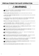
PRECAUTIONS FOR SAFE OPERATION It is imperative that the user complies with this manual as it contains important safety advice. Items and procedures are described so that you can use this unit correctly and safely. If the precautions advised are followed, this will prevent possible injury to the user and any other person. Precautions are illustrated in the following way: /WARNING Failure to observe WARNING signs could result in a hazard fo personnel possibly resulting in serious injury or death. /N\CAUTION
PRECAUTIONS FOR SAFE OPERATION Do not use the unit outdoors, Current leakage or electric shock may result if the unit is exposed to rain water. Only qualified engineers or service personnel should install the unit. The installation by unqualified personnel may cause electric shock or fire. Install the unit on a sturdy floor and take an adequate precaution to prevent the unit from turning over.
PRECAUTIONS FOR SAFE OPERATION WARNING 0 Ensure you do not inhale or consume medication or aerosols from around the unit at the time of maintenance. These may be harmful to your health. @ Never splash water directly onto the unit as this may cause electric shack or hart circuit Never put containers with liquid on the unit as this may cause electric shock or short circuit when the liquid is spilled. Never bind, process, or step on the power supply cord, or never damage or break the power supply pig.
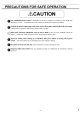
PRECAUTIONS FOR SAFE OPERATION CAUTION | Use a dedicated power source (a dedicated circuit with & breaker) as indicated on the rating label attached to the unit. A branched circuit may cause fire resulting from abnormal heating. Connect the power supply plug to the power source firmly after removing the dust on the plug. A dusty plug or improper insertion may cause a heat or ignition. ® Never store corrosive substances such as acid or alkali in this unit if the container cannot be sealed.
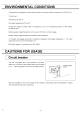
ENVIRONMENTAL CONDITIONS This equipment fs designed to be safe at least under the following conditions (based on the [EC 61010-1): 1. Indoor use; 2. Altitude up to 2000 m; 3. Ambient temperature 5°C to 40°C 4. Maximum relative humidity 80% for temperature up to 31°C decreasing linearly to 50% relative humidity at 40°C; 5. Mains supply voltage fluctuations not to exceed £10% of the nominal voltage; 8. Other supply voltage fluctuations as stated by the manufacture; 7.
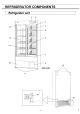
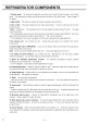
REFRIGERATOR COMPONENTS 1. Control panel: The chamber superstructure and alarms can be set through the keys on the control panel. The temperature indicator and lamps are also provided on the control panel. Refer to page 10 for details 2. Light switch: This switch is used for turning the fluorescent lamp off and on. 3. Door switch: This switch detects the door status {open/close). The door check lamp is ON when the door is open. 4. Door: Sliding type.
REFRIGERATOR COMPONENTS Control panel components DOC ALARM m__a 1. Door check indicator (DOOR): The red LED lamp is lit when the door is opened, + 2 minutes after the door check indicator ON, the buzzer is activated to notice the door opening 2. Alarm indicator (ALARM): The red LED lamp blinks during an alarm condition. See page 22. 3. Temperature display: Normally shows the present chamber temperature and during an alarm condition, shows an error code. See page 23. 4.
INSTALLATION SITE 1 To operate this unit properly and to obtain maximum performance, install the unit in a location with the following conditions 4 A location not compliance with the following conditions may cause poor performance, failure or accident. » A location not subjected to direct sunlight Do not install the unit under direct sunlight.
INSTALLATION 1. After unpack aging Remove all transportation packaging materials and tapes. Pen the doors and ventilate the unit, If the outside panels are dirty, clean them with a diluted neutral dish washing detergent < Undiluted detergent can damage the plastic components. For the dilation, refer to the instruction of the detergent < After the cleaning with the diluted detergent, always wipe it off with a wet cloth. Then wipe off the panels with a dry cloth. 2.
START-UP OF UNIT 13 Follow the procedures for the initial and consequent operations of the unit. 4 At the recovery after power failure, the operation is start-up automatically with the setting before power failure. See page 20 1. Connect the power supply cord to the dedicated outlet with appropriate rating. If the unit is unplugged or the power to the unit is interrupted, do not restart the unit for at least 5 minutes. This protects the compressor. 2.
CHAMBER TEMPERATURE SETTING Set the chamber temperature according to the condition of use. This refrigerator can keep the stored items for long period under appropriate temperature. ® Setting range of chamber temperature: between 2 and 14°C ® [initial setting (factory setting. 5°C important The chamber temperature of 2°C may cause partial freeze of stored items. Example: Change the chamber temperature to 4°C from 5°C » Following shows a sample setting.
LOCK OF CHAMBER TEMPERATURE The setting of chamber temperature can be protected to avoid an accidental change.
DEFROST OF EVAPORATOR The following 2 kinds of defrost methods are provided with this refrigerator. Both defrost methods are controlled automatically. ™ Cycle defrost To keep the charterer temperature stable, the refrigeration compressor is yodeled on and off. During “off” period any frost which has accumulated on the evaporator is melted by energizing a defrost heater.
17 ALARM TEMPERATURE SETTING Setting of high temperature alarm By setting the high temperature alarm, the alarming indicator and temperature display blinks and alarm buzzer operates {after 15 minutes) when the chamber temperature is over the setting of high temperature alarm. Set the high temperature alarm to protect the stored items against the damage resitting from temperature rise.
ALARM TEMPERATURE SETTING Setting of low temperature alarm By setting the low superstructure alarm, the alarm indicator and temperature display blinks and alarm buzzer operates (after 15 minutes} when the chamber temperature is over the setting of low temperature alarm. Set the low temperature alarm to protect the stored stems against the damage resulting from temperature lowering.
SETTING OF DELAY OF DOOR ALARM 19 The door check indicator is light when the door is opened, and the alarm buzzer sounds with some delay o notice the door opening The delay time (between lighting of the door check indicator and activation of the alarm buzzer) can be changed. Set an appropriate delay time according to the condition of use to prevent the rise of chamber temperature resulting from inadequate door close. = Setting range of delay time. 1 and 15 minutes = [initial setting (factory reffing.
SETTING OF RING BACK OF ALARM BUZZER The alarm buzzer operates again after certain period (ring back time) even if the alarm buzzer is silenced by pressing the alarm buzzer stop key (BUZZER) when the same alarm status is continued. Set the ring hack time to prevent the misidentify the alarm status. ® Setting range of ring back time.
REMOTE ALARM TERMINAL 21 The alarm status is noticed to a remote location when a remote alarm equipment {commercial item) is connected to the remote alarm terminal. 1t is recommended to install a2 remote alarm equipment {commercial inert) when the refrigerator is installed in a desolate location so they an alarm status is noticed to an operator < Contact Sonya representative or agent for the installation of a remote alarm equipment (commercial freemen. & Location of remote alarm terminal.
ALARM FUNCTIONS This unit has the alarms functions shown below. effing. Alarms Situation Indication Arm buzzer Remote alarm High temp. Alarm indicator blinks. Intermittent tone with Alarm status with alarm 9 P Charier temp. blinks. 15 minutes delay. 15 minutes delay. Alr circulation If the chamber temp. distribution gets worse Alarm indicator blinks: Intermittent tone with Alarm status with Door afar When the door is open. blinks. 2 minutes delay.
SELF DIAGNOSTIC FUNCTIONS This unit has the self diagnostic functions shown below. Self diagnostic Situation Indication Alarm buzzer Remote alarm . Alar indicator blinks. if the thermal sensor is disconnected EQ1 and chamber temp. is displayed alternately. . Alarm indicator blinks. If the thermal sensor is . E02 and chamber temp. short-circuited. . is displayed alternately. f the defrost sensor is Alar rm indicator blinks: E03 and chamber temp. disconnected o Sensor is displayed alternately.
ROUTINE MAINTENANCE WARNING Always disconnect the power supply to the unit prior to any repair or maintenance of the unit in order to prevent electric shock or injury. Ensure you do not inhale or consume medication or aerosols from around the unit at the time of maintenance. These may be harmful to your health. Cleaning of exterior, interior, and accessories Use a dry cloth to wipe off small amounts of dirt on the outside and inside of the unit and all accessories.
ROUTINE MAINTENANCE Replacement of fluorescent lamp Follow the procedure below when replacing & fluorescent lamp. The fluorescent lamp is located horizontally at upper front of the cabinet. 1. Turn off the light switch and disconnect the power supply plug of the refrigerator. Fluorescent lamp 2. Move the stored terns on the top shelf and in the top drawer (M PR-514R} 3. Pull the fluorescent lamp downwards from the stopper together with the lamp cover and wiring. [Fig. 4] 4.
ROUTINE MAINTENANCE Cleaning of evaporating tray 1. As shown in Fig. 6, remove 2 screws on the bottom of the unit cover and remove the unit cover. 2. The evaporating tray is installed in the back. Pull the clips an the both sides of the mourning plate loosen the mounting plate. Take out the evaporating tray with the mounting plate as shown in Fig. 7. 3. Dispose any accumulated water in the evaporating tray. 4. Wash the evaporating tray with a diluted neutral dish washing detergent and clean water.
TROUBLESHOOTING 27 If the unit malfunctions, check out the following before calling for service. Malfunction Check/Remedy If nothing operates even when plugged in Thai unit is not connected to the power supply properly. + The capacity and voltage of power supply is not sufficient. There is a power failure. 1+ The circuit breaker on the supply circuit is activated.
DISPOSAL OF UNIT A WARNING If the unit is to be stored unused in an unsupervised area for an extended period ensure that children do not have access and doors cannot be closed completely. The disposal of the unit should be accomplished by appropriate personnel. doors o prevent accidents such as suffocation.
33 AUTOMATIC TEMPERATURE RECORDER The chamber temperature is recorded and maintained by attaching an automatic temperature recorder available as an optional accessory. For the attachment of an automatic temperature recorder, an optional recorder mounting kit is necessary. Automatic temperature recorder Recorder mounting kit M TR-0821LH M PR-S30 M TR-GO4A (AC 100 to 150 V) M TR-GU4C (AC 220 to 240 V) 4 Contact Sonya sales representative or agent for the attachment of an automatic temperature recorder.
INSTALLATION OF RECORDER Attachment of recorder M TR-0621LH 1. Remove the bottom shelf (bottom right drawer for M PR-514R) in the chamber. favor RPM-514, remove the doors before taking out the bottom shelf. 2. Precursor the sower fixing the panel cover at the space for automatic temperature recorder and open the panel cover. [Fig. 8] 3. Remove the panel cover from the shaft by pushing the shaft edge to the right and left side respectively. 4.
35 INSTALLATION OF RECORDER 7. Fix the recorder sensor to the sensor fixture. [Fig. 12] 8. Replace the insulation to the sensor port and then replace and fix the air intake vent cover by 2 screws, 9. Set the automatic temperature recorder with the frame to the space for automatic temperature recorder. [Fig. 13] 10. Replace the bot torn shelf (bottom right drawer for M PR-514R} in the chamber. “For RPM-514, replace the doors after setting the bot torn shelf.
INSTALLATION OF RECORDER Attachment of recorder M TR-G04A or M TR-G04C 1. Remove the bottom shelf (bottom right drawer for M PR-514R) in the chamber. w Far RPM-514, remove the doors before taking out the bottom shelf. 2. Precursor the sower fixing the panel cover at the space for automatic temperature recorder and open the panel cover. [Fig. 14] 3. Remove the panel cover from the shad by pushing the shaft edge to the right and left side respectively. 4.
37 7. Fix the recorder sensor to the sensor fixture. [Fig. 18] 8. Replace the insulation to the sensor port and then replace and fix the air intake vent cover by 2 screws, 9. Concert the recorder connector fo the connector for reorder power located at upper right inside the space for automatic temperature recorder. [Fig. 19) <+ The connector for recorder power has a connector cover. Remove the connector cover before connection. 10.
BATTERY FOR POWER FAILURE ALARM The alarm indicator blinks and the alarm buzzer sounds to notice the power failure when a battery for power failure alarm is installed. For the installation of the battery for power failure alarm, & mounting kit {M PR-48B), an optional component is necessary. A battery for power failure alarm is included in the mounting kit. Contact Sonya sales representative or agent for the installation of the mounting kit (M PR-48B). 1.
BATTERY FOR POWER FAILURE ALARM 39 8. Put the battery future over the battery and fix the battery box and battery fixture by 4 screws. [Fig. 24] 8. Connect the harness fo the battery connector and battery switch [Fig. 25] and bind the harnesses by the clip on the battery fixture. [Fig. 24] 7. Cover the opening beside the battery switch with the fop cover removed in procedure 1 (4 screws). The harness in no use is bound by the clip on the back of the top cover. 8.
SETTING FOR BATTERY BEFORE STARTING Always perform the settling shown below after the installation of battery for power allure alarm, an optional component (M PR-48B). The chamber temperature and “E0" is displayed on the temperature display alternately if the battery switch is turned on without following procedure. < Turn off the battery switch, perform the following setting, and turn on the battery switch again if *E09” is displayed on the temperature display.
SPECIFICATIONS 41 Name Pharmaceutical Refrigerator Model RPM-514 M PR-514R External dimensions VW00 x DEMO + (58) x H1790 (rmm) Internal dimensions WWB00 x D485 x H1300 {mm) Effective capacity 489 1 486 L Exterior Painted steel Interior Stainless steel Dewar Sliding type, 2-layer pair glass with heat ray reflection film x 2 Insulation Rigid polyurethane foamed-in place Shelves Hard steel wire on polyester coating x § Hard steel wire on polyester coating x 5 Allowable load; 50 kg/shelf Allowable load; 20 kg/
PERFORMANCE Model RPM-514, M PR-514R Temperature control range +2°C to +14°C Usable ambient temperature -5°C o +35°C Noise level 42 dB (A scale) Maximum pressure 1500 kPa Rated voltage AC110V | AC115Y | AC220V | AC220V | AC230V | AC240V Rated frequency: 680 Power consumption 240 W 240 W 240 W 215W 220W 220W < The above data is measured based on our internal basis. < Design or specifications will be subject fo change without notice.
43 A\ CAUTION Please fill in this form before servicing. Hand over this form to the service engineer to keep for his and your safety. 1. Refrigerator contents : Risk of infection: Risk of toxicity: Risk from radioactive sources: C Yes Limeys Ll Yes [Yes Safety check sheet CNo Line Lino INo {List all potentially hazardous materials that have been stored in this unit)) Notes : 2. Contamination of the unit Unit interior No contamination Decontaminated Contaminated Others: C Yes Limeys Ll Yes C Yes 3.