CONTENTS INTRODUCTION PRECAUTIONS FOR SAFE OPERATION ENVIRONMENTAL CONDITIONS REFRIGERATOR COMPONENTS inside of front panel Control panel INSTALLATION SHE INSTALLATION START-UP OF UNIT STOCK OF CONTAINERS CHAMBER TEMPERATURE SETTING KEY LOCK FUNCTION ALARM TEMPERATURE SETTING SETTING OF DELAY OF DOOR ALARM SETTING OF RING BACK OF ALARM BUZZER OPERATION CHECK AFTER RECOVERY DEFROST CYCLES REMOTE ALARM TERMINAL ALARMS & SAFETY FUNCTIONS ROUTINE MAINTENANCE Cleaning of cabinet Cleaning of evaporating tray Repl
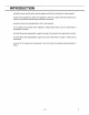
INTRODUCTION u Read this manual carefully before using the appliance and follow the instructions for safety operation. » Sonya never guarantee any safety if the appliance is used for any objects other than intended use or used by any procedures other than haste mentioned in this manual. = Keep this manual in an adequate place to refer {o it as necessary. = The contents of the manual will be subjected o change without notice due to the improvement of performance or functions.
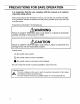
PRECAUTIONS FOR SAFE OPERATION It is imperative that the user complies with this manual as it contains important safety advice. Terns and procedures are described so that you can use this unit correctly and safely. if the precautions advised are followed, this will prevent possible injury to the user and any other person, Precautions are illustrated in the following way: /\WARNING Failure to observe WARNING signs could result in a hazard to personnel possibly resulting in serious injury or death. /A\CAUTION
PRECAUTIONS FOR SAFE OPERATION WARNING Do not use the unit outdoors, Current leakage or electric shock may result if the unit is exposed to rain water. Only qualified engineers or service personnel should install the unit. The installation by unqualified personnel may cause electric shock or fire, install the unit on a sturdy floor and take an adequate precaution to prevent the unit from turning over.
PRECAUTIONS FOR SAFE OPERATION WARNING o Ensure you do not inhale or consume medication or aerosols from around the unit at the time of maintenance. These may be harmful to your heath. ® Never splash water directly onto the unit as this may cause electric shock or short circuit, Never put containers with liquid on the unit as this may cause electric shock or short circuit when the liquid is spilled, Never bind, process, or step on the power supply cord, or never damage or break the power supply plug.
PRECAUTIONS FOR SAFE OPERATION CAUTION Use a dedicated power source {a dedicated circuit with a breaker) as indicated on the rating label attached to the unit. A branched circuit may cause fire resulting from abnormal heating. Connect the power supply plug to the power sauce firmly after removing the dust on the plug. A dusty plug or improper insertion may cause a heat or ignition. Never store corrosive substances such as acid or alkali in this unit if the container cannot be sealed.
ENVIRONMENTAL CONDITIONS This equipment is designed fo be safe at least under the following conditions (based on the |EC 81010-1): 1. Indoor use; 2. Altitude up to 2000 rmy; 3. Ambient temperature 5°C to 40°C 4. Maximum relative humidity 80% for temperature up to 31°C decreasing linearly to 50% relative humidity at 40°C; 5. Mains supply voltage fluctuations not to exceed £10% of the nominal voltage; 6, Other supply voltage fluctuations as stated by the manufacture; 7.
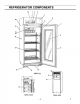
REFRIGERATOR COMPONENTS 1. Front cover: Open this cover when connecting the remote alarm or replacing glow stater for fluorescent lamp. 2. Control panel: The chamber temperature and alarms can be set through the keys on the control panel. The temperature indicator and lamps are also provided on the control panel. Refer to page 11. 3. Light switch: This switch is used for turning the fluorescent lamp off and on, 4.
REFRIGERATOR COMPONENTS Inside of front cover 1. Glow starter {with cover}: This is for the fluorescent fight. It is recommended that the glow starer is also replaced when the fluorescent light is replaced. Refer to page 21. 2. Remote alarm terminal: This is used to connect the unit to an exterior alarm to notify users of any malfunction.
REFRIGERATOR COMPONENTS Control panel SHAH DOOR ALARM TEMPER CREATURE} BUZZER SET Door alarm lamp (DOOR}): This lamp is lit when the door is opened. 2. Alarm lamp (ALARM): This lamp flashes during an alarm condition. 3. Digital temperature indicator: This indicator shows the present chamber temperature or set temperature. 4, Numerical value shift key { 2 }: Pressing this key in the set mode causes the numerical value to scroll up. ON-OFF of key lock can be selected by pressing this key in the key lock mode.
INSTALLATION SITE To operate this unit properly and to obtain maximum performance, install the unit in a location with the following conditions: = A location not subjected to direct sunlight Do not instant the unit under direct sunlight. Installation in a location subjected to direct sunlight cannot obtain the intended performance. ® A location with adequate ventilation Leave at least 10 cm around the unit for ventilation.
INSTALLATION 13 1. Removing the packaging materials and tapes Remove all transportation packaging materials and tapes. Open the doors and ventilate the unit. I the outside panels are dirty, clean them with a diluted neutral dish washing detergent, (Undiluted detergent can damage the plastic components. For the dilution, refer to the instruction of the detergent.) After the cleaning with the diluted detergent, always wipe it off with a wet cloth. Then wipe off the panels with a dry cloth. 2.
START-UP OF UNIT Folio the procedures for the initial and consequent operations of the unit, 1. Connect the power cord to the dedicated outlet with appropriate rating. CAUTION if the unit Is unplugged or the power fo the unit is interrupted, do not restart the unit for at least 5 minutes, This protects the compressor. 2. On start-up, the alarm buzzer sometimes operates. (n this case, stop the buzzer by pressing the alarm buzzer stop key (BUZZER). 3. Set the chamber temperature to 5°C. 4.
STOCK OF CONTAINERS 16 Always distribute items so as not to disturb the air circulation in the chamber. Disruption of the air flow can cause items to freeze or reduce the uniformity of the chamber temperature. Never put any artistes on the top of the unit. Air intake vent Do not block this vent with containers. If this vent becomes blocked, temperature regulation becomes unstable. Do into place paper or vinyl near the vent as they may be sucked into the fan.
CHAMBER TEMPERATURE SETTING Table 1 shows the basic procedure for setting the chamber temperature. Perform key operations in the sequence indicated in the table. The example in the table is based on the assumption that the desired temperature is 4°C. Note: The unit is set at the factory with a chamber temperature of 5°C. Table 1 Basic operation sequence (Example: Chamber set temperature 4°C) Description of operation Key operated Indication after operation 1 |Tum the power switch ON. — Zine .
ALARM TEMPERATURE SETTING 17 This unit is provided with both high and low temperature alarms. The temperature at which the alarm is activated may be changed. The available set range for high temperature afar is between +2°C and +14°C and -2°C and -14°C for iow temperature alarm against the chamber temperature, Note: The temperature alarm is set of the set temperature at the factory.
SETTING OF DELAY OF DOOR ALARM The door check indicator is light when the door is opened, and the alarm buzzer sounds with moss delay ta native the door opening. The delay time {between lighting of the door check indicator and activation of the alarm buzzer) can be changed.
SETTING OF RING BACK OF ALARM BUZZER The alarm buzzer operates again after certain period {ring back time) even if the alarm buzzer is silenced by pressing the alarm buzzer stop key {BUZZER} when the same alarm status is confined. Set the ring back time to prevent the misidentify the alarm status.
DEFROST CYCLES There is no need for routine defrosting of the unit as this occurs automatically as follows: w Cycle defrost To keep the chamber temperature stable, the refrigeration compressor is cycled on and off, During OFF period any frost which has accumulated on the evaporator is melted by energizing a defrost heater. This will nat have any discernible effect on the chamber temperature.
ROUTINE MAINTENANCE /\WARNING Always disconnect the power supply to the unit prior to any repair or maintenance of the unit in larder to prevent electric shock or injury. Ensure you do not inhale or consume medication or aerosols from around the unit at the time of maintenance. These may be harmful to your heath. A\CAUTION Always wear dry gloves to protect hands at the time of maintenance. Failure to wear gloves may resit in injury from edges and comers. Cleaning of cabinet » Clean the unit once a month.
ROUTINE MAINTENANCE Replacement of fluorescent lamp Follow the procedure below when replacing a fluorescent lamp. The fluorescent damp is located horizontal at upper front of the cabinet. 4. Turn off the light switch and disconnect the power supply plug of the refrigerator. 2. Move the stored items on the top shelf and in the top drawer. 3. Gulf the fluorescent lamp downwards from the stopper together with the lamp cover and wiring. [Fig. 1] 4.
TROUBLE SHOOTING if the unit malfunctions, check out the following before calling for service. Malfunction Check/Remedy If nothing operates even when switched on * There is a power failure. = The circuit breaker is activated. * The unit is not connected to the power supply. ‘When no key operation is * The key lock is stein ON (L 1). available The alarm device is < On start-up > activated » The temperature in the unit does not match the set value, sinus * The door was kept opened for a long time.
DISPOSAL OF UNIT WARNING i the unit is to be stored unused in an unsupervised area for an extended period ensure that children do not have access and doors cannot be closed completely. The disposal of the unit should be accomplished by appropriate personnel. Always remove doors to prevent accidents such as suffocation.
OPTIONAL COMPONENTS Automatic temperature recorder An automatic temperature recorder is available for this refrigerator as an optional accessory. If an automatic temperature recorder is required, contact your Sonya dealer. Recorders available are the M TR-0821LH and the M TR-GO4A or M TR-GO4C, Please note that each recorder needs a different fixture. See the following for the details.
OPTIONAL COMPONENTS Attachment of recorder M TR-0621LH 31 1. Follow the instruction manual provided with the temperature recorder and attach the recorder to the fixture M PR-S30. 2. Open the aperture for the recorder on the front top of the unit by removing the locating screw and remove the cover by pushing the shaft on both sides outwards. {Fig. 1) 3. Attach the recorder to the front cover with the s Crow. 4.
OPTIONAL COMPONENTS Attachment of recorder M TR-G04A or M TR-G04C 1. Fallow the instruction manual provided with the temperature recorder and attach the recorder to the fixture RPM-87. 2. Open the aperture for the recorder on the front top of the unit by removing the locating screw and remove the cover by pushing the shaft on both sides outwards. (Fig) 3. Remove the black rubber caps {inside and outside} Fig.
OPTIONAL COMPONENTS Attachment of battery kit M PR-48B The alarm lamp blinks and the alarm buzzer sounds to notice the power failure when a battery for power failure alarm is installed. For the retaliation of the battery for power failure alarm, a battery kit (M PR-488), an optional component is necessary. A battery for power failure alarm is included in the battery kit. = Contact Sonya sales representative or agent for the installation of the battery kit (M PR-488}. 1.
OPTIONAL COMPONENTS 6. Connect the harness fo the battery connector and battery switch [Fig. 3] and bind the harnesses by the sip on the battery fixture. [Fig. 2] 7. Cover the opening beside the battery switch with the top cover removed in procedure 1 (four screws), The harness i no use is bound by the clip on the back of the top cover. To the M TR-480C 8. Put the battery box cover over the hatter box and fix the patter box cover with screws {three screws on the right and left). Fig.
OPTIONAL COMPONENTS Setting for battery before starting 35 Always perform the setting shown below after the installation of battery for power failure alarm, an optional component (M PR-488). The chamber temperature and “E09 is displayed on the temperature display alternately if the battery switch is turned on without following procedure. * Turn off the battery switch, perform the following setting, and turn on the battery switch again if "E09" is displayed on the temperature display.
SPECIFICATIONS Name Pharmaceutical Refrigerator Model RPM-721 I M PR-721R External dimensions W770 x D830 x H1955 (mm) internal dimensions W50 x D710 x H1500 (mm) Effective capacity 6841 [ 671 L Exterior Painted steel Interior Painted steel Door Double layer pair glass/steel plate, automatic closing mechanism insulation Rigid polyurethane foamed-in place Shelf Hard steel wire on polyethylene coating 4 ps. (Max. load; 80 kg/shelf} ) Drawer Painted steel 5 pes. (Max.
A CAUTION Please fill in this form before servicing. Hand over this form to the service engineer to keep for his and your safety. Safety check sheet 1. Refrigerator contents : O Yes China Risk of infection: [I Yes INe Risk of toxicity: [I Yes Ci No Risk from radioactive sources: [Yes [No {List all potentially hazardous materials that have been stored in this unit.) Notes : 2.