Operating Instructions FULL HD LCD Display h English Please read these instructions before operating your set and retain them for future reference.
Table of Contents Important Safety Notice............................................ 3 Safety Precautions.................................................... 4 Accessories............................................................... 7 Accessories Supply.................................................. 7 Remote Control Batteries......................................... 7 Connections............................................................... 8 AC cord connection and fixing, cable fixing..............
Important Safety Notice WARNING 1) To prevent damage which may result in fire or shock hazard, do not expose this appliance to dripping or splashing. Do not place containers with water (flower vase, cups, cosmetics, etc.) above the set. (including on shelves above, etc.) No naked flame sources, such as lighted candles, should be placed on / above the set. 2) To prevent electric shock, do not remove cover. No user serviceable parts inside. Refer servicing to qualified service personnel.
Safety Precautions WARNING Setup This LCD Display is for use only with the following optional accessories. Use with any other type of optional accessories may cause instability which could result in the possibility of injury. • Pedestal........................................................ KA-TD-47NE1 Always be sure to ask a qualified technician to carry out set-up. Small parts can present choking hazard if accidentally swallowed. Keep small parts away from young children.
Safety Precautions When using the LCD Display The Display is designed to operate on 220 - 240 V AC, 50/60 Hz. Do not cover the ventilation holes. • Doing so may cause the Display to overheat, which can cause fire or damage to the Display. Do not stick any foreign objects into the Display. • Do not insert any metal or flammable objects into the ventilations holes or drop them onto the Display, as doing so can cause fire or electric shock. Do not remove the cover or modify it in any way.
Safety Precautions CAUTION When using the LCD Display Do not bring your hands, face or objects close to the ventilation holes of the Display. • Heated air comes out from the ventilation holes at the top of Display will be hot. Do not bring your hands or face, or objects which cannot withstand heat, close to this port, otherwise burns or deformation could result. Be sure to disconnect all cables before moving the Display.
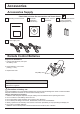
Accessories Accessories Supply Check that you have the accessories and items shown Operating Instruction book CD-ROM (Operating instructions) Remote Control Transmitter Batteries for the Remote Control Transmitter (R6 (UM3) Size × 2) Power supply cord Remote Control Batteries Requires two R6 batteries. 1. Pull and hold the hook, then open the battery cover. 2. Insert batteries - note correct polarity ( + and -). 3. Replace the cover.
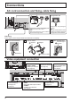
Connections AC cord connection and fixing, cable fixing AC cord fixing Unplug the AC cord Plug the AC cord into the display unit. Plug the AC cord until it clicks. Note: Make sure that the AC cord is locked on both the left and right sides. Unplug the AC cord pressing the two knobs. Note: When disconnecting the AC cord, be absolutely sure to disconnect the AC cord plug at the socket outlet first. Cable fixing Fix the cable in place using the bead band attached to the display.
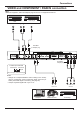
Connections VIDEO and COMPONENT / RGB IN connection Note: Additional equipment, cables and adapter plugs shown are not supplied with this set.
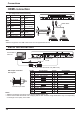
Connections HDMI connection [Pin assignments and signal names] Pin No. 1 2 3 4 5 6 7 8 9 10 Signal Name Pin No. 11 T.M.D.S Data2+ T.M.D.S Data2 Shield T.M.D.S Data2T.M.D.S Data1+ T.M.D.S Data1 Shield T.M.D.S Data1T.M.D.S Data0+ T.M.D.S Data0 Shield T.M.D.S Data0T.M.D.S Clock+ Signal Name T.M.D.S Clock Shield 12 T.M.D.S Clock- 13 CEC 14 Reserved (N.C.
Connections PC Input Terminals connection (Female) COMPUTER Shared with DVI-D IN. Audio Stereo mini plug (M3) Connect a cable which matches the audio output terminal on the computer. Conversion adapter (if necessary) RGB PC cable with Ferrite core Mini D-sub 15p (Male) Notes: • Computer signals which can be input are those with a horizontal scanning frequency of 30 to 110 kHz and vertical scanning frequency of 48 to 120 Hz.
Connections SERIAL Terminals connection The SERIAL terminal is used when the Display is controlled by a computer. (Male) COMPUTER 1 2 6 RS-232 Cross cable (sold separately) 3 7 4 8 5 9 Pin layout for SERIAL Terminal (Female) D-sub 9p Notes: • Set up the computer to be connected and the communication RS-232 cross cable that connects the SERIAL terminal with the computer. • The computer shown is for example purposes only. • Additional equipment and cables shown are not supplied with this set.
Power On / Off Connecting the AC cord plug to the Display. Connecting the plug to the Wall Outlet Notes: • Main plug types vary between countries. The power plug shown at right may, therefore, not be the type fitted to your set. • When disconnecting the AC cord, be absolutely sure to disconnect the AC cord plug at the socket outlet first. Press the Power switch on the Display to turn the set on: Power-On.
Power On / Off When first switching on the unit Following screen will be displayed when the unit is turned on for the first time. Select the items with the remote control. Unit buttons are invalid. OSD Language English (UK) OSD Language Deutsch 1 Français Select the language. Italiano Español 2 ENGLISH (US) Set. Select PRESENT TIME Setup 1 Select “DAY” or “PRESENT TIME”. 2 Setup “DAY” or “PRESENT TIME”. 1 Select “Set”.
Selecting the input signal Press to select the input signal to be played back from the equipment which has been connected to the Display. Input signals will change as follows: PC DVI HDMI1 HDMI2 VIDEO Component* PC: PC input terminal in PC IN. DVI: DVI input terminal in DVI-D IN. HDMI1: HDMI input terminal in AV IN (HDMI1). HDMI2: HDMI input terminal in AV IN (HDMI2). VIDEO: Video input terminal in AV IN (VIDEO/S-VIDEO). Component*: Component or RGB input terminal in COMPONENT/RGB IN.
Basic Controls Main Unit Brightness Sensor Detects the brightness in the viewing environment. Remote control sensor Power Indicator The Power Indicator will light. • Power-OFF ���� Indicator not illuminated (The unit will still consume some power as long as the power cord is still inserted into the wall outlet.) • Standby �������� Red • Power-ON ������ Green • Power management (DPMS) �����������������������Orange (PC IN or DVI-D IN signal.
Basic Controls Remote Control Transmitter ACTION button Press to make selections. ASPECT button Press to adjust the aspect. (see page 18) Sound mute On / Off Press this button to mute the sound. Press again to reactivate sound. Sound is also reactivated when power is turned off or volume level is changed. AUTO SETUP button Automatically adjusts the position/ size of the screen. (see page 22) N button (see page 23, 24, 25, 26) POSITION buttons INPUT button Press to select Input signal sequentially.
ASPECT Controls The Display will allow you to enjoy viewing the picture at its maximum size, including wide screen cinema format picture. Note: Be aware that if you put the display in a public place for commercial purposes or a public showing and then use the aspect mode select function to shrink or expand the picture, you may be violating the copyright under copyright law.
Digital Zoom This displays an enlargement of the designated part of the displayed image. 1 Display the operation guide. Press to access Digital Zoom. The operation guide will be displayed. Exit 1 During Digital Zoom, only the following buttons can be operated. [Remote control] POSITION / ACTION button 2 Select the area of the image to be enlarged. Press on the enlargement location to select. The cursor will move. Exit 2 3 Select the magnification required for the enlarged display.
On-Screen Menu Displays Remote Control Unit 1 Display the menu screen. Press to select. (Example: Picture menu) 2 Select the item. Select. Picture Normalise Press. Normal Picture Mode Backlight Contrast Brightness Colour Tint Sharpness White balance Advanced settings 100 70 50 50 50 50 Press several times. Each time the MENU button is pressed, the menu screen will switch. Normal Viewing Picture Setup Sound Pos. /Size Normal Select.
On-Screen Menu Displays Overview Note: Menu that cannot be adjusted is grayout. Adjustable menu changes depending on signal, input and menu setting. Pos.
Adjusting Pos. /Size 1 2 Press to select the menu to adjust. 3 Press to adjust the menu. 4 Pos. /Size Press to display the Pos. /Size menu. Press to exit from adjust mode. Normalise Auto Setup H-Pos H-Size V-Pos V-Size Clock Phase Dot Clock 1:1 Pixel Mode Normal 0 0 0 0 0 0 Off Notes: Unadjustable items are grayed out. Adjustable items differ depending on the input signal and the display mode.
Adjusting POS. /SIZE H-Pos Adjust the horizontal position. V-Pos Adjust the vertical position. H-Size Adjust the horizontal size. V-Size Adjust the vertical size. Clock Phase (During Component, RGB and PC input signal) Eliminate the flickering and distortion. Dot Clock (During Component, RGB and PC input signal) Periodic striped pattern interference (noise) may occur when a striped pattern is displayed. If this happens, adjust so that any such noise is minimized.
Picture Adjustments 1 Press to display the Picture menu. 2 Select to adjust each item. Press to select the menu to adjust. Select the desired level by looking at the picture behind the menu. Note: Menu that cannot be adjusted is grayout. Adjustable menu changes depending on signal, input and menu setting. Picture Normalise Press “ ” or “ ” button to switch between modes.
Picture Adjustments Item Backlight Contrast Brightness Colour Tint Sharpness Effect Darker Adjustments Brighter Adjusts luminance of the back light. More Selects the proper brightness and density for the room. Less Darker Brighter Less More Reddish Greenish Less More Adjusts for easier viewing of dark pictures such as night scenes and black hair. Adjusts colour saturation. Adjusts for nice skin colour. Notes: • “Colour” setting can be adjusted for Video input signal.
Sound Adjustment 1 Sound Press to display the Sound menu. Normalise 2 Select to adjust each item. Press to select the menu to adjust. Select the desired level by listening to the sound. 3 Normal Sound Mode Bass Treble Balance Surround AUDIO OUT (PIP) 0 0 0 Normal Off MAIN Press to exit from adjust mode. Item Sound Mode Details Normal: Emits the original sound. Dynamic: Accentuates sharp sound. Clear: Attenuates human voice. Bass Adjusts low pitch sounds. Treble Adjusts high pitch sounds.
PRESENT TIME Setup / Set up TIMER The timer can switch the Display On or Off. Before attempting Timer Set, confirm the PRESENT TIME and adjust if necessary. Then set POWER ON Time / POWER OFF Time. 1 2 Press to display the Setup menu. Press to select Set up TIMER or PRESENT TIME Setup. Press to display the Set up TIMER screen or PRESENT TIME Setup screen.
PRESENT TIME Setup / Setup TIMER Set up TIMER Set the program for turning the power On/Off and select the input signal at the specified time. Up to 20 programs can be set. [Setting Example] Program 1, Every Monday, 12:00, Power On, Input: VIDEO Set up TIMER PRESENT TIME MON 0 : 03 1 Program On Timer Function MON Day Power Mode Power On Time 12 : 00 Input VIDEO 1 Set the program number. 2 To execute the program, set to “On”. The program is disabled when “Off” is set. 3 Set the day.
Screensaver (For preventing image retention) Do not display a still picture, especially in 4:3 mode, for any length of time. If the display must remain on, a Screensaver should be used. When the screen saver is operating, the following 5 patterns are displayed full screen for 5 seconds each. Black→Dark Gray→Gray→Light Gray→White 1 Press to display the Setup menu. 2 Setup 1/2 Signal Screensaver Input label Wobbling Component/RGB-in select Press to select Screensaver.
Screensaver (For preventing image retention) Setup of Screensaver Time After selecting Time Designation, Interval or Standby after SCR Saver, the relevant Time Setup will become available for selection and the Operating Time may be set. (Time cannot be set when “Mode” is “On” or “Off”.) Press to select Start Time / Finish Time (When Time Designation is selected). Press to select Periodic Time / Operating Time (When Interval is selected).
Reduces power consumption • Power management: When this function is set to On, it operates under the following conditions to turn the power on or off automatically. When no pictures are detected for 30 or so seconds during input from PC IN or DVI-D IN terminal: → Power is turned off (standby); the power indicator lights up orange. When pictures are subsequently detected: → Power is turned on; the power indicator lights up green.
Customizing the Input labels This function can change the label of the Input signal to be displayed. (see page 15) 1 2 3 Setup Press to display the Setup menu. Press to select Input label. Press to display the Input label screen. Signal Screensaver Input label Wobbling Component/RGB-in select Power management Auto power off Standby save ECO OSD Language Off RGB Off Off Off(SERIAL) Off English(UK) Press to select image input. Press to change input label.
Selecting the On-Screen Menu Language 1 2 Press to display the Setup menu. Press to select the OSD Language. Press to select your preferred language. Selectable languages English (UK) Deutsch Français Italiano Español Setup 1/2 Signal Screensaver Input label Wobbling Component/RGB-in select Power management Auto power off Standby save ECO OSD Language Off RGB Off Off Off(SERIAL) Off English(UK) English (US) ......(Chinese) .......(Japanese) Русский.......
Setup for MULTI DISPLAY By lining up the Displays in groups, for example, as illustrated below, an enlarged picture may be displayed across all screens. For this mode of operation, each display has to be set up with a Display number to determine its location. (Example) group of 4 (2 × 2) group of 9 (3 × 3) group of 16 (4 × 4) group of 25 (5 × 5) How to Setup MULTI DISPLAY 1 Setup Press to display the Setup menu. Press to select the MULTI DISPLAY Setup.
Setup for MULTI DISPLAY Item Details Select the required arrangement number. (A1-E5 : Refer to the following) Display Number locations for each arrangement. (Examples) ( 2 × 1) ( 2 × 3 ) Location 4 (4×2) (4×4) (5×5) A1 A2 A3 A4 B1 B2 B3 B4 A5 B5 C1 C2 C3 C4 C5 D1 D2 D3 D4 D5 E1 E2 E3 E4 E5 Press to exit from Setup.
Setup for Input Signals Component / RGB-in select Select to match the signals from the source connected to the COMPONENT/RGB IN terminal. Y, PB, PR signals “Component” RGB signals “RGB” 1 2 Press to display the Setup menu. Press to select the “Component / RGB-in select”. Press to select the desired input signal. Component 3 RGB Press to exit from adjust mode. Note: Make setting of the selected input terminal (COMPONENT/RGB IN).
Setup for Input Signals Signal menu Note: “Signal” setup menu displays a different setting condition for each input signal. Setup 1 2 3 4 1/2 Press to select the “Signal”. Signal Screensaver Input label Wobbling Component/RGB-in select Press to display the Signal menu. Power management Auto power off Standby save ECO OSD Language Press to display the Setup menu. RGB Off Off Off(SERIAL) Off English(UK) Press ACTION ( ) button Press to select the menu to adjust. Press to adjust the menu.
Setup for Input Signals Colour system Select Signal from the “Setup” menu during Video (S Video) input signal. (“Signal [AV]” menu is displayed.) Press to select the “Colour system”. Press to select each functions. [ AV ] Signal 3D Y/C Filter Colour system Cinema reality Noise reduction On Auto Off Off If the picture image becomes unstable: With the system set on Auto, under conditions of low level or noisy input signals the image may in rare cases become unstable.
Setup for Input Signals [ AV ] Signal Noise reduction Press to select “Noise reduction”. 3D Y/C Filter (NTSC) Colour system Cinema reality Noise reduction On Auto Off 4:3 Off Press to select “Off”, “Auto”, “Min”, “Mid”, “Max”. Auto: Noise reduction will be automatically selected from “Min”, “Mid” or “Max”. Note: Noise reduction can be adjusted while a Video or Component signal is being applied. Sync This function operates only during input from PC IN terminal.
Setup for Input Signals Input signal display Displays the frequency and the type of the current input signal. This display is valid only for Component / RGB / PC and Digital input signal. Display range: Horizontal 30 - 110 kHz Vertical 48 - 120 Hz The dot clock frequency is displayed during digital signal input. Note: The automatically detected signal format may be displayed differently than the actual input signal.
Options Adjustments 1 Options Press to display the Setup menu. On screen display Initial input Initial VOL level Maximum VOL level Input lock Button lock Remocon User level Press to select “OSD Language”. 2 Press for more than 3 seconds. Press to select “Options”. 3 1/2 On Off Off 0 Off 0 Off Off Off Options Options Shipping Press to display the Options menu.
Options Adjustments Item Adjustments Off On MENU&ENTER Off: All the buttons on main unit can be used. MENU&ENTER: Locks Button lock MENU and ENTER/ buttons on main unit. On: Locks all the button on main unit. Sets Button lock with the unit buttons in the following procedure.
Troubleshooting Before you call for service, determine the symptoms and make a few simple checks as shown below. Picture Symptoms Sound Interference Noisy Sound Normal Picture No Sound No Picture No Sound No Picture Normal Sound No Colour Normal Sound No remote control operations can be performed. A cracking sound is sometimes heard from the unit. The top or bottom of the picture on the screen is cut off when I use the zoom function.
Applicable Input Signals PC signals *Mark: Applicable input signal Horizontal Vertical RGB IN PC IN DVI-D IN HDMI1 frequency (kHz) frequency (Hz) (Dot clock (MHz)) (Dot clock (MHz)) (Dot clock (MHz)) HDMI2 640x400@70Hz 31.46 70.07 * (25.17) * (25.17) * (25.17) 640x400@85Hz 37.86 85.08 * (31.5) * (31.5) * (31.5) 640x480@60Hz 31.43 59.88 * (25.15) * (25.15) * (25.15) 640x480@60Hz 31.47 59.94 * (25.18) * (25.18) * (25.18) * 640x480@67Hz 35.00 66.67 * (30.24) * (30.24) * (30.24) 640x480@72Hz 37.86 72.
Applicable Input Signals Component signals Signal name 1 2 3 4 5 6 7 8 9 10 11 12 13 14 15 16 525(480)/60i 525(480)/60p 625(575)/50i 625(576)/50i 625(575)/50p 625(576)/50p 750(720)/60p 750(720)/50p 1,125(1,080)/60p 1,125(1,080)/60i 1,125(1,080)/50p 1,125(1,080)/50i 1,125(1,080)/24sF 1,125(1,080)/30p 1,125(1,080)/25p 1,125(1,080)/24p *Mark: Applicable input signal HDMI1 Horizontal Vertical COMPONENT IN DVI-D IN frequency (kHz) frequency (Hz) (Dot clock (MHz)) (Dot clock (MHz)) HDMI2 15.73 59.94 * (13.
Specifications PID-42NE1 Power Source Power Consumption Power on Stand-by condition Power off condition LCD Display panel Screen size (No.of pixels) Operating condition Temperature Humidity Applicable signals Colour System Scanning format PC signals Connection terminals AV IN VIDEO S-VIDEO AUDIO L-R HDMI 1/2 COMPONENT/RGB IN G/Y B/PB/CB R/PR/CR AUDIO L-R DVI-D IN AUDIO PC IN 240 W 0.2 W 0.
Information for Users on Collection and Disposal of Old Equipment and used Batteries EU These symbols on the products, packaging, and/or accompanying documents mean that used electrical and electronic products and batteries should not be mixed with general household waste. For proper treatment, recovery and recycling of old products and used batteries, please take them to applicable collection points, in accordance with your national legislation and the Directives 2002/96/EC and 2006/66/EC.
N9AP/N9BP SANYO Electric Co., Ltd.