PJ-Net Organizer MODEL No.
Compliance and Caution Compliance Federal Communication Commission Notice This equipment has been tested and found to comply SANYO POA-PN40 with the limits for a Class B digital device, pursuant to Tested To Comply part 15 of the FCC Rules. These limits are designed With FCC Standards to provide reasonable protection against harmful interference in a residential installation.
Compliance and Caution CAUTION ON USE IN NETWORK - When you receive an alert e-mail from the projector, you must check the projector immediately. Fire or accident may result if the projector is used in an abnormal condition. - When you install the projector at remote location and use it through the network, you must perform the safety inspections periodically. In this case you must pay attention to the change of environment in which you installed the projector.
Contents Compliance ..............................................................................................................2 Federal Communication Commission Notice.......................................................2 Trademarks ..........................................................................................................2 Contents ...................................................................................................................4 Chapter 1 Preparation ...............
Contents Save the controls and settings ...........................................................................49 Save/delete the settings ....................................................................................49 Check the saved items ......................................................................................50 Load a control set ..............................................................................................50 Timer setting .......................................
Chapter 1 Preparation 1 ENGLISH Describes features and operating environment of this product.
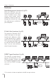
Chapter 1 Preparation Features Web Management function (☞p.39) With this function, you can monitor projector functions such as power status, lamp status, input mode, signal condition, lamp-use time, etc. through the network by using the web browser installed on your computer. PC2 PC1 PJ1 PJ2 PC3 PC6 PC4 PC5 Turn on PJ2. E-Mail Alert function (☞p.32) The projector (Network Unit) sends messages to the registered e-mail addresses when a lamp abnormality or power failure occurs on the projector.
Features Multi-control function (☞p.56) A single computer can control and set up the multiple projectors at the same time. PJ1 PJ3 PJ2 PJ4 PC6 PC5 Select Input 2 for PJ1 to PJ4 PC4 Automatic On/Off using Clock function (☞p.51) Automatically turn on or off the projectors at specified date/day and time by using the clock function. I am ready to turn ON, and select Input 3 (Video) Now it’s 11:30 Control port ready for external equipment (☞p.
Chapter 1 Preparation Operating environment To perform the managing and setting up the projector using this product, the environment described below is required. Operating System Standard mode*1 : Windows 98, Windows Me, Windows 2000, Windows NT4.0 SP6, Windows XP Network Network must handle Ethernet correctly and accept TCP/IP protocol. Computer The computer must provide a 10Base-T or 100Base-TX network card. Web browser application* ● Microsoft Internet Explorer version 5.0, 5.5 or 6.
Operating environment The limitation of connection between this product and hub or computer *1 Suitable LAN cables are limited by length and type as follows; Connection Type of usable LAN cable Maximum length Network Unit - Hub UTP Straight Cable with category 3 or 5 * 100m Network Unit - Computer UTP Cross Cable with category 3 or 5*2 100m 2 *1 There may be other limitations depending on your network environment or LAN specification.
Chapter 1 Preparation 12
Chapter 2 Installation 2 ENGLISH Describes how to install the Network Unit, and configure the network.
Chapter 2 Installation Flow of installation The following are instructions for attaching this product to the projector and connecting it to the network. Please review the entire procedure to become familiar with it. 1 Function of the Network Unit (☞ p.15) Explains the name and functions of each part of the Network Unit. 2 Installation and network configuration (☞ p.16-22) 1 Mount this product onto the projector. 2 Connect the LAN cable and join it to the network.
Name and function of each part [1] Name and function of each part (Top View) Power indicator This lights up red when the network function is set ON in the projector menu. Mounting screws Mount by using a coin etc. (☞ p.16) LIN K ACT ACT indicator This turns on and off when sending or receiving of data LINK indicator This lights up orange when the Network Unit is connected to the network correctly. (Bottom View) Connector plug Connecting to the terminal on the projector. (☞ p.
Chapter 2 Installation [2] Installation and network configuration Mounting 1 Disconnect the AC plug from the projector. 2 Remove the connector cover and screw Connector cover covers (2 pieces) from the projector and insert plug on this product to the option connector. Screw cover 3 Tighten two screws by using a coin etc. ! 16 Caution ✐ AC cord must be disconnected when mounting or removing this product otherwise it may damage the product.
Installation and network configuration Connection of LAN cable To connect to the network, it is required to use the UTP (Unshielded Twisted Pair) straight cable with RJ-45 plug. There are two different types of cables depending on whether the network is constructed with 10Base-T or 100Base-TX. Prepare the Hub (10Base-T or 100Base-TX) to distribute the network cable if required. 1 Disconnect the AC plug from the projector. 2 Connect the UTP straight cable to the LAN port on the Network Unit.
Chapter 2 Installation Network configuration Confirmation of the network menu When installing this product to the projector, the network on-screen menu items for this product are activated automatically. If not activated, the product may not have been installed correctly. Please check item "Mounting" (☞ p.16). Configure the network Before performing the network configuration, prepare network address numbers (IP Address, Subnet Mask, Default Gateway, DNS) assigned to the projector.
Installation and network configuration 2 Configuration for IP Address/ Sub net/ Gateway*1/DNS*2 Press SELECT button again. The following network setting pallet appears on the screen. Enter the specified network addresses. The red frame moves sequentially left or right with 7 8 button. The number up or down with d e button.
Chapter 2 Installation Network PIN code setting The network PIN code can be set to restrict access to the setting page of the projector using the web browser. ✽ Default network PIN code [0000] means no network PIN code is set. 1 Displaying network PIN code menu Select network menu and then select "Network PIN code" sub menu. Press SELECT button twice to display the Network PIN code entry pallet. * The number on the pallet is the current network PIN code.
Installation and network configuration How to enter the numbers with the screen 10-key pallet 1 Select a column with a red frame by using the point buttons 7 8 . 2 Press SELECT button. The screen 10-key pallet appears on the screen. 3 By using the point buttons(d e 7 8), select numbers 0 to 9 and press SELECT button. By repeating the above to enter the complete number on the column.
Chapter 2 Installation Notice about system construction For installation of multiple projectors into the same network with Network Unit. Do not install multiple projectors with Network Units that have their default network settings to the same network. The use of the Network Units which have the default IP address set to the same network settings will cause IP addresses to collide and create a malfunction.
Chapter 3 Basic Setting and Operation 3 ENGLISH Describes basic operations and settings for controlling the projector by using the web browser. It is required that computer and projector is connected to the network and the network address is properly configured.
Chapter 3 Basic Setting and Operation Login the setting page of the projector 1 Enter the IP address Launch the web browser installed in your computer, enter the IP address into the "Address" on the browser and then press "Enter" key. Enter the address (192.168.1.201) that you configured in item "Network configuration" (☞ p.18). The default IP address is [192.168.0.2]. 2 Select a display mode and login This product provides 2 types of control mode, Standard Mode and Light Mode as the below.
Login the setting page of the projector 3 Display of main setting page The following main setting page will be displayed according to your display mode selection. Perform various kinds of settings through this page. Click on the menus to display the control and setting pages. z Main setting page in the Standard Mode display Clock display Display on or off by clicking text ON or OFF Sub menu tab Switches the sub menu tab. Page numbers Switches the pages by clicking the number's tab.
Chapter 3 Basic Setting and Operation x Main setting page in the Light Mode display Sub menu tab Page numbers Returns to the display mode selection page. Main menu Setting page Returns to main menu ✐ The blank page appears if your PDA does not provide a Macromedia Flash Player. You need to install the Macromedia Flash Player. (☞p.25) How to use the setting page To control and set up the projector, use the setting menus on the web browser.
How to use the setting page Type of the setting pallet Text box setting Enter a number or text and then click Set button. or Change a value with ▲ or ▼ button and then click Set button. The value changes quickly when keeping pressing ▲ or ▼ button. Pull-down menu setting Select an item with pulldown menu button and then click Set button. or Select an item by clicking ▲ or ▼ button.
Chapter 3 Basic Setting and Operation Initial setting After installing this product to the projector, perform the following basic initial setting. Click Initial Setting on the main menu to display the initial setting page. There are two sub menus, Initial setting and Serial Port setting sub menu. PIN code, Temperature unit, Date and Time can be set on Initial setting page, and Serial Port setting page is used for controlling the external equipment through the RS-232C serial port.
Initial setting Network PIN code setting This is to set the network PIN code to restrict the access from an unauthorized person through the network. Enter a 4-digit number as the network PIN code onto the text box and click Set button. The Network Unit begins restarting and it takes about 20 seconds. Close (Quit) the web browser and access to the login page again in 20 seconds. This is to perform the login authentication firmly. The default network PIN code [0000] means no network PIN code is set.
Chapter 3 Basic Setting and Operation Item Description Time setting ....... When clicking AUTO button, the time which is set on your computer is set to the Network Unit. Date ...................Sets date in manual Time...................Sets time in manual Date and time setting Auto setting Click AUTO button on the page, the time which is set on your computer is set to the Network Unit. Note: Confirm that your computer has a correct clock time before performing the auto time setting.
Network configuration Network configuration Click Network on the main menu. The following setting page is displayed. This page is to set the IP Address, Subnet Mask, Default Gateway, DNS (Domain Name Server) and projector name. The IP address and Subnet Mask have been configured already in chapter "Installation". If you want to change them or configure default gateway or DNS, perform them in this page. Enter an applicable address number onto each parameter and click Set button.
Chapter 3 Basic Setting and Operation E-mail setting This product has an E-mail function which can send an alert message to users or an administrator if it detects an abnormality on the projector or run out of the life span of the lamp. Click E-mail Setting on the main menu and follow the below steps. Item Description SMTP server*1 ....... Sets server name or IP address of the SMTP server Administrator address ..............Sets e-mail address of administrator Add e-mail address ..............
E-mail setting 2 Registering and deleting E-mail addresses Click "Add e-mail address" and type the e-mail address onto the text box and click Set button. To check the registered addresses, click Check/Delete sub menu tab. The addresses are listed as the figure on the right. ✐ Up to 10 E-mail addresses can be registered. Check / Delete To delete the registered addresses, check the address you want to delete and click Delete button. 3 Option selection for sending alert mail Click Option sub menu tab.
Chapter 3 Basic Setting and Operation Examples: Type and contents of alert mail When the projector has an abnormality, the following alert messages are sent to the registered E-mail address according to your selected condition. Administrator or user can take an efficient action quickly by receiving this message. This is very useful to maintain and service the projector. The following are examples of received messages.
E-mail setting ● When the life span of lamp is reached: TITLE: Message from projector 10-03-2005 00:59 Projector Model Name: model name TCP/IP: 192.168.1.201 Projector Name: Proj05 It sends you following message. *The life-span of lamp is reached. Lamp replacement is required. ✐ Replace it with a new lamp immediately and reset the lamp counter. If the projector is used without resetting the lamp counter, the alert mail is sent to users in every power-on of the projector.
Chapter 3 Basic Setting and Operation SNMP setting This product provides a SNMP (Simple Network Management Protocol) agent function. The SNMP consists of a manager and agents. The group which communicates information each other with SNMP is called "Community". There are two access modes in a community, Refer (read only) and Set (read- write). This product allows to use Refer (read only) only. The SNMP message informs the projector status called "Trap" to an administrator.
SNMP setting Trap Item Description Community name ... Enter community name to send "Trap". Default name is "public". Trap address ...... Enter IP address of the SNMP manager computer to receive "Trap". Trap check/delete Check and delete the trap address Checking the registered trap address and deleting the address. To delete the address, tick check box in front of the IP address and click Delete button. ✐ Up to 10 trap addresses can be registered.
Chapter 3 Basic Setting and Operation 38
Chapter 4 Controlling the Projector 4 ENGLISH Describes controlling and setting of the projector by using the web browser.
Chapter 4 Controlling the Projector Power control and status check Click Power & Status on the main menu. The control page will be displayed. By clicking ON or Standby button on the page, the power of the projector can be controlled. Confirmation window appears when the Standby button is pressed. Popup confirmation window Item Description PJ status Power ................... Displays the status of the lamp. (ON, OFF, On starting up, On cooling down) Status ...................
Power control and status check About projector condition Status Description Normal ..............................................Projector is operating normally. Power management in operation ......Power management is operating Lamp failure ......................................Lamp failure is occurring Abnormal Temperature .....................The temperature of the projector became too high Cooling down after Abnormal Temp. ............ Projector detects abnormal temp. and is cooling down itself.
Chapter 4 Controlling the Projector Controls Click Control on the main menu. The setting method differs depending on the contents of the page. Click on the page number to change pages and select desired setting items. ✐ Please see the owner's manual of the projector to have the further information of each control item. Input This function is to select the input mode and source mode of the projector. Click Set button after selecting the input and source mode. Item Description Input ..................
Controls System This function is to select the system of signal input to the projector. The available system mode are listed on the pull-down menu button according to the input signal. Select a system and then click Set button. Available selection when the Computer[Analog] input Item Description XGA1 ................. It automatically switches to the proper computer system of the input signal. * The computer system modes (VGA, SVGA, XGA. SXGA, UXGA, WXGA...) which meet the input signal are listed.
Chapter 4 Controlling the Projector Image adjustment This function is to adjust the projected picture image and save the image mode. To store the adjusted value, click Store button, and to load the adjusted value, click Load button. Item Description Contrast .............Adjusts picture contrast (0~ 63) Brightness .........Adjusts picture brightness (0~ 63) Color ..................Adjusts picture color saturation (0~ 63) Tint.....................Adjusts picture hue (0~ 63) Item Description Color Temp.
Controls Sound This function is to adjust the sound of the projector. The values in the text box represent the current control value or status. Item Description Volume............... Adjusts the sound volume from the speakers.(0 ~ 63) Mute................... Suppresses the sound. (ON, OFF) Menu This function is to control the On-screen menu of the projector. Switches menu on/ off, moves menu selection (cursor) and selection. Item Description ENGLISH Display ...............
Chapter 4 Controlling the Projector PC adjustment Click PC Adj. on the main menu. This function is to adjust the signal from the computer connected to the projector to obtain the proper picture image on the screen. Item Description Current mode ..... Displays a current mode like VGA, SVGA, XGA. SXGA, UXGA, WXGA, etc. or MODE1 - MODE10, EXT11 - EXT50 which are the customized mode created by using the "Mode Store" function described below. Auto PC adj. ...... Performs automatic adjustment. Fine sync. ....
Setting up the projector Setting up the projector Click Setting on the main menu. This function is to set up the projector. Select the sub menu [Screen setting] or [Setting] and then set up each setting. Item Description Screen ............... Switches the screen mode. (Full, Zoom, Normal, Natural wide, True) There may not be available mode depending on the input mode as shown in the table below. Ceiling................ Sets the image top/bottom and left/right reversed. (ON, OFF) Rear ..................
Chapter 4 Controlling the Projector Item Description Logo .................. Sets on or off the logo display on the screen during the startup. (Default, My logo, OFF) Background ....... Sets screen background to blue when no signal input. (Blue, My logo, Black (OFF)) Display ............... Switches on or off the on-screen menu display on the screen.(ON, OFF, CountdownOff) Freeze................ Sets the image to freeze mode.(ON, OFF) Power management......
Save the controls and settings Save the controls and settings This page is to save and load the controls and settings of the projector in the block. The storable items are "PC adjustment", "Control" and "Setting". Save/delete the settings 1 Click Save menu on the main menu. 2 Select a set number (Totalsave1 to Totalseve10) you intend to store current settings with the pull-down menu button of the item Save & Delete. Name this set number onto the Memo text area.
Chapter 4 Controlling the Projector Check the saved items Click Check button to check the current setting condition of the controls. Each item of "PC adj.", "Control" and "Setting" is displayed sequentially. Click Stop button to cancel the auto page display. Load a control set Select your desired set number (Totalsave1 to Totalsave10) with the pulldown menu button of Load Set and then click Load button. The setting values of the selected set number are applied to the current settings.
Timer setting Timer setting This page is to set the timer to turn the projector off or on at a programmed day/date and time. Follow the steps below for setting. Click Timer on the main menu. Present time set on the Network Unit Select date Select day Set execute time Event action How to set the timer 1 Set a day or date To set the timer event at same time everyday or every week, Select day entry with radio button and then select desired day with the pull-down menu button.
Chapter 4 Controlling the Projector 2 Set an execute time Type the time with (Hour:Minute) and 24 hours format. Ex.: Type [18:25] if you specify [PM 6 o’clock and 25 minutes]. 3 Select an event action Select an event action from the pull-down menu. Event Action ON ......................Turns on the projector OFF ....................Turns off the projector Lamp Auto ..........Changes lamp mode to "Auto" Lamp Eco ...........Changes lamp mode to "Eco" Lamp Normal......
Timer setting Notes on timer setting ✐ Up to 10 timer events can be registered. Timer events always operate according to the next valid event depending on the projector's power status. In the example below, event 3 turns on the projector so next event 4 (also turning on projector) will not be effective because the projector is already turned on. Similarly, when the projector is turned off by event 5, event 6 OFF will not be effective in turning it off again.
Chapter 4 Controlling the Projector Projector information This page is to display the basic information of the projector status. Click Information on the main menu. Items Description Input ..................Displays selected input and source. System...............Displays selected signal system. Signal.................Input signal status (Yes, No) Screen ...............Displays screen mode. Lamp status ........ Displays lamp status with an animation. Refer to the table on the next page. Security .......
Projector information Indication of the lamp status Icon display/background Status White-Yellow/Blue Lamp on (Normal) White-Yellow/Red Lamp on (Lamp is being used over a specified use time, replace lamp immediately) Gray/Blue Lamp off (Normal) Gray/Red Lamp off (Lamp is being used over a specified use time, replace lamp immediately) Red/Blue with X Lamp failure (Lamp failure, check lamp condition) Red/Red with X Lamp failure (Lamp failure and lamp is being used over a specified use time, replace
Chapter 4 Controlling the Projector Multi-control Controlling and setting the multi-projectors This function enables you to control the multiple projectors equipped with the Network Units that are connected to the network. Click Multi Control on the main menu to display the control page. Note: To control the multiple projectors, each projector must have the same Network PIN code.
Multi-control Start/stop the multi control To start or stop controlling the multi-projectors, click Multi control setting menu and select ON or OFF. Switches on and off the multi-control function Multi control setting OFF .....Stops multi control function ON ....... Starts multi control function. The multi control menu will appear when setting ON. These items of menu are linked to the main menu.
Chapter 4 Controlling the Projector Register the projector To use the multi control function, register the IP address of the projector you intend to control. Click PJ registration sub menu tab and set the IP address and Memo, then click Set button. Items Description IP address ......... Enter IP address of the projector to control Memo................. Enter projector name or installed location etc. Confirmation of registered projector To check the registered information, click Conf.
Multi-control Change the mode of the registered projector To change the mode of the registered projector, select a mode with the pull-down menu button under the IP address of the target projector and then click Set button. Mode Operation Control ................. Multi-controlling the projector OFF..................... Excluding from the multi-control Delete .................. Deleting from the multi-control * This function is not available with the Light mode.
Chapter 4 Controlling the Projector Conf. & Change page in the light mode Following functions in the "Conf. & Change" page are not available in the light mode. - Changing the control mode. - Deleting the registered IP address - Indicating the each status - Indicating the each memo This indicates that the mode is "Control". (Conf.&Change page in the light mode) Controlling all together "Power & Status", "PC adjustment", "Control" and "Setting" can be controlled all together.
Chapter 5 Use of Serial Port 5 ENGLISH Describes controlling the external equipment connected with the RS-232C port.
Chapter 5 Use of Serial Port This product provides a serial control port (RS-232C) to control the external equipment through the serial cable. This function allows you to control the external equipment connected to the serial port on the Network Unit through the network, and control the projector through the serial cable with the external serial controller. Before connecting the external equipment, perform the setting "Serial Port setting" described below.
Serial port setting Setting examples for the serial control Setting for controlling the equipment connected to the serial port from the computer. Serial Control Port number Other Settings :Selects "External" :Sets according to the computer specified port no. Do not use port number 10000*2. :Sets according to the communication condition of the equipment Setting for controlling the projector from the serial controller connected to the serial port.
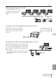
Chapter 5 Use of Serial Port Control examples Example 1 Controlling AV equipment through network. Video/Audio PJ2 DVD Player LAN cable PC5 Playback DVD RS-232C serial cable Example 2 Controlling a projector not provided with the network function through network. PJ2 PJ1 LAN cable PC5 64 Turn on the PJ1.
Control examples Example 3 Controlling the projector with the serial controller through the serial port (RS-232C). PJ3 PJ2 PJ1 RS-232C serial cable ENGLISH Serial controller ✐ Use proper serial cable depending on the connected equipment port specification. Please refer to "Port Specification" of the serial port specification of this product (☞ p.78).
Chapter 5 Use of Serial Port Use of telnet You can control the external equipment connected to the serial port on the Network Unit by using the telnet application*1 installed on your computer. The following is a control example of external equipment. The telnet application is needed to use commands*2 which control the external equipment. Preparation 1 Disconnect the AC plug from the outlet and connect an external equipment to the serial port with an RS-232C serial cable.
Use of telnet 3 When communication is established, the word "PASSWORD:" appears on the window. Type the login password (PIN code) for the projector and then press "Enter" key on the keyboard. If you do not set up the network PIN code, just press "Enter" key. When the word "Hello" is replied, login has been succeeded. 4 Type the commands from the key board to control the external equipment and then press "Enter" key for termination. For example, type "C00" and press "Enter" key.
Chapter 5 Use of Serial Port Control the projector with telnet This product allows you to control the projector by using the telnet application. Normally, it is used for controlling the external equipment connected to the serial port but it also controls the projector by specifying the telnet port number 10000. * To control the projector with telnet application is not depending on the serial port setting. In the step 2 of the previous page, enter port number "10000" after the IP address number. > open 192.
Chapter 6 Appendix 6 Examples of connection Web browser setting Technical data ENGLISH Q&A PJ-NET ORGANIZER OWNSER'S MANUAL 69
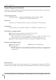
Chapter 6 Appendix Examples of connection Peer-To-Peer connection Connecting the projector (PJ01) to the control computer (PC05) directly. * UTP cross cable Computer Name: PC05 IP Address Subnet Mask Default Gateway DNS Projector Name: PJ01 : 192.168.0.5 : 255.255.255.0 : : IP Address Subnet Mask Default Gateway DNS : 192.168.0.2 : 255.255.255.0 : 0.0.0.0 : 0.0.0.0 Connecting the projector (PJ01) to the control computer (PC05) via the hub.
Examples of connection The gateway (Router) installed in the network Connecting the projector (PJ01) to the control computer (PC05) via the gateway. Entrance hall Computer Name IP Address Subnet Mask Default Gateway DNS : PC205 : 192.168.200.5 : 255.255.255.0 : 192.168.200.1 : 192.168.201.1 Monitor Name: PJ01 IP Address Subnet Mask Default Gateway DNS : 192.168.200.15 : 255.255.255.0 : 192.168.200.1 : 192.168.201.1 Hub Network Group: 192.168.200.
Chapter 6 Appendix Web browser setting This product is designed to enable the projector to be set up and controlled from an Internet web browser. Depending on the preference settings of the web browser, some control functions may not be available. Please make sure that the following functions are set up properly in the web browser. Active Script/JavaScript enable There are some control items used with the JavaScript function in the setting pages.
Web browser setting Examples: OS/Browsers Windows XP Professional Internet Explorer v.6.0 ActiveScript setting ENGLISH Select Internet Options menu from Tool menu on the web browser and then select Security tab and click Customize Level… button. On the security setting window, scroll down and find the Scripting item, make sure that "Enable" is selected in item Active Scripting.
Chapter 6 Appendix Proxy setting Select Internet Options menu from Tool menu on the web browser and then select Connection tab and click LAN Settings button. Properly set up your web browser's the proxy server settings according to the local area network environment to which the projector is connected. - Using proxy server To use an external internet connection from the local area network, check the item Use a proxy server and enter the proxy server address and port correctly in the proxy settings window.
Web browser setting Netscape Navigator v.7.0 JavaScript Setting ENGLISH Select Preference menu from Edit menu on the web browser and then select the item Advanced/Scripts & Plug-ins in the Category column. Make sure that the Enable JavaScript for Navigator is checked.
Chapter 6 Appendix Proxy setting Select Preference menu from Edit menu on the web browser and then select the item Advanced/Proxies in the Category column. Properly set up your web browser's the proxy server settings according to the local area network environment to which the projector is connected. - Using proxy server When you use an external internet connection from the local area network, select the item Manual proxy configuration.
Product specification Product specification Type.......................................PJ-Net Organizer (Network Unit) LAN interface ........................Applicant regulation IEEE802.3 (10Base-T) IEEE802.3u (100Base-TX) Data transfer speed 10Mbps/100Mbps Data transfer mode Half duplex/Full Duplex Terminal 8-pin modular (RJ-45) Network protocol .................. TCP/IP specification TCP/IP Serial interface ......................RS-232C Baud rate 0.3/1.2/2.4/4.8/9.6/19.2/28.8/57.6/115.
Chapter 6 Appendix Port specification LAN port specification 8-pin modular connector (RJ-45) 12 3 4 5 6 7 8 Pin No. Signal 1 TX+ Transfer data (+) Function 2 3 4 5 6 7 8 TXRD+ (not used) (not used) RD(not used) (not used) Transfer data (-) Receive data (+) Receive data (-) Serial port specification D sub 9-pin connector (RS-232C) 5 4 9 2 7 1 6 Pin No.
Q&A Q&A Installation/Access Q Why doesn’t the setting page appear in my web browser? A Following causes are possible. Please check them. 1. The projector does not connect to the network. Check LED indicators status (☞ p.15). - Check the connection of LAN cable if the LINK indicator does not light orange. - Check the network configuration of the projector if ACT indicator does not light green. 2. Function "Network" in the projector is not set to "ON". Set up by using the projector’s on-screen menu (☞ p.
Chapter 6 Appendix 3. Enter the projector’s IP address [192.168.0.2] at "Address" column on the Web browser. [Note] Make sure that the proxy setting of your web browser is set "Not using proxy server" (☞ p.74, 76). 4. If the login page appears, this product is operating properly. The problems may be in the network configuration of the computer or in the network. Please try to set up the network by following item "Network configuration" (☞ p.18).
Q&A Q How can I install several projectors equipped with the Network Unit? A Install and configure network one by one to avoid the IP address collision each other (☞ p.22). To configure the IP address please see item "Network configuration" (☞ p.18). Q How many projectors can I control with multi-control function? A It has been designed to control up to 100 sets but it depends on the network environment.
Chapter 6 Appendix Operation Q Why can't I change the controls in the setting page with web browser? A Please make sure the projector is turned on. If it is in the standby mode, the setting is not effective to the projector. To control the projector with a web browser, the projector must be in the powered-on condition. Also, projectors registered for multi-control cannot have any controls changed if they are in standby mode.
Q&A Q Why am I not receiving E-mail alert messages? A Make sure that the registered E-mail address and SMTP server address are correct. If the SMTP server is located in your LAN (Local Area network), the address should be set to the SMTP server in your LAN. The SMTP server located outside of your LAN may not be available for security reason. For further information please contact your network administrator (☞ p.32). It may be required for the authentication depending on the SMTP server.
Chapter 6 Appendix Q Can I update the firmware of the Network Unit? A It is possible to update the firmware through the network. It is required to have a special tool for the updating. For further information please consult your local dealer. The version number of the firmware is indicated on the lower part of the "Initial Setting" page. (☞ p.
Q&A Q What are the rules for IP address assignment? A If the network is constructed with TCP/IP protocol, a unique IP address is required for each piece of network equipment. The following are basic rules of the assignment. Rule1 Do not configure the same IP address to the network equipment in the same network group. Each piece of equipment must be assigned a unique IP address. If the IP address is set [192.168.x.x], the Subnet Mask should be set [255.255.255.0] for example. Rule2 The start address [xxx.
Printed in Japan 1AA6P1P5006-- (IDZG) SANYO Electric Co., Ltd.