Network Supported Multimedia Projector MODEL PLC-XL51 Owner’s Manual ❏ Wireless LAN ❏ Wired LAN Memory Viewer IEEE802.11b/g 100-Base-TX/10-Base-T ❏ SD Memory Card Viewer ✽ Refer to the owner’s manual below for details about network and memory viewer function.
Features and Design This Multimedia Projector is designed with the most advanced technology for portability, durability, and ease of use. This projector utilizes built-in multimedia features, a palette of 16.77 million colors, and matrix liquid crystal display (LCD) technology. ◆ Large Screen in Limited Space Short focus lens allows you to project large images from short distance (p.14). Images can be projected on the floor.
Table of Contents Features and Design . . . . . . . . . . . . . . . . . . . . . . . . 2 Table of Contents . . . . . . . . . . . . . . . . . . . . . . . . . . . 3 To the Owner . . . . . . . . . . . . . . . . . . . . . . . . . . . . . . 4 Safety Instructions . . . . . . . . . . . . . . . . . . . . . . . . .
To the Owner Before installing and operating the projector, read this manual thoroughly. The projector provides many convenient features and functions. Operating the projector properly enables you to manage those features and maintains it in good condition for many years to come. Improper operation may result in not only shortening the product life, but also malfunctions, fire hazard, or other accidents.
Safety Instructions All the safety and operating instructions should be read before the product is operated. Read all of the instructions given here and retain them for later use. Unplug this projector from AC power supply before cleaning. Do not use liquid or aerosol cleaners. Use a damp cloth for cleaning. Follow all warnings and instructions marked on the projector.
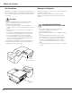
Safety Instructions Air Circulation Moving the Projector Openings in the cabinet are provided for ventilation. To ensure reliable operation of the product and to protect it from overheating, these openings must not be blocked or covered. When the projector is not in use for an extended period, put it into a suitable case. Handle the projector carefully; do not drop, bump, subject it to strong forces, or put other things on the cabinet. CAUTION Hot air is exhausted from the exhaust vent.
Safety Instructions Installing the Projector in Proper Position Install the projector properly. Improper Installation may reduce the lamp life and cause fire hazard. Side B Side A CAUTION – Do not put anything or sit on the projector, otherwise, it may fall down or cause failure of the projector or injury. – Choose the running speed of cooling fans in the fan control setting according to the altitude in which the projector is being used (p.54). Failure to do so may affect the projector life.
Compliance Federal Communications Commission Notice This equipment has been tested and found to comply with the limits for a Class B digital device, pursuant to Part 15 of the FCC Rules. These limits are designed to provide reasonable protection against harmful interference in a residential installation. This equipment generates, uses, and can radiate radio frequency energy. If it is not installed and used in accordance with the instructions, it may cause harmful interference to radio communications.
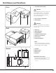
Part Names and Functions q Infrared Remote Receiver Front CAUTION The Infrared Remote Receiver sticks out of the cabinet surface. If the Infrared Remote Receiver is put on the wall or floor directly, the Infrared Remote Receiver may damage. w Top controls and Indicators e Exhaust Vent CAUTION q w e Back Hot air is exhausted from the exhaust vent. Do not put heat-sensitive objects near this side.
Part Names and Functions Side Terminal q w r e t y u i o q LAN Connection Terminal Connect the LAN cable (refer to the owner’s manual “Network Set-up and Operation”). w SERVICE PORT This jack is used to service the projector. e COMPUTER IN 1 Connect output signal from a computer, or RGB scart 21pin video output to this terminal (pp.16, 18). When the cable is of the longer variety, it is advisable to use this terminal and not COMPUTER IN 2/MONITOR OUT.
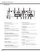
Part Names and Functions Top q w e r t o y !0 u i q ALARM indicator Blinks red to indicate the battery condition or key operation. y INPUT button Select input source (pp.27, 37, 38). u POINT ( ed7 8 ) buttons w POWER indicator – Lights red when the projector is in stand-by mode. – Lights green during operations. – Blinks green in the Power management mode (pp.50, 70). e WARNING indicator – Lights red when the projector detects an abnormal condition.
Part Names and Functions Remote Control @1 @2 q ON/STAND-BY button Turn the projector on or off (pp.20, 21). @3 w COMPONENT button Select COMPONENT input source. q e AUTO PC button Automatically adjust the computer image to its optimum setting (pp.26, 29). r KEYSTONE button Correct the keystone distortion (pp.24, 45). t CANCEL button Return to the menu bar in Memory Viewer menu. See the owner's manual of “Memory Viewer function”.
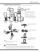
Part Names and Functions Remote Control Battery Installation 1 Open the battery compartment lid. 2 Install new batteries into the compartment. 3 Replace the compartment lid. Two AA size batteries For correct polarity (+ and –), be sure battery terminals are in contact with pins in the compartment. To ensure safe operation, please observe the following precautions: ● Use two (2) AA or LR6 type alkaline batteries. ● Always replace batteries in sets. ● Do not use a new battery with a used battery.
Installation Positioning the Projector For the projector positioning, see the figures below. The projector should be set perpendicularly to the plane of the screen. A A ✔Note: • This projector is not equipped with an optical zoom. To adjust the screen size, change the throw distance. • The brightness in the room has a great influence on picture quality. It is recommended to limit the ambient lighting in order to get the best image. • All measurements are approximate and may vary from the actual sizes.
Installation Mounting the Rear Leg and the Stand Rear Leg 1 Turn off the projector and unplug the AC power cord. 2 Secure the rear leg with the four (4) screws. Screw Rear leg Stand* 1 Turn off the projector and unplug the AC power cord. 2 Secure the stand with three (3) sets of the screw with a washer. * The stand is included in standard accessories. Stand ✔Note: • Make sure not to lose screws when installing the rear leg or the stand.
Installation Connecting to a Computer Cables used for connection • VGA Cables (Mini D-sub 15 pin)* • Audio Cables (Mini Plug: stereo) (*One cable is supplied; other cables are not supplied with the projector.
Installation Connecting to Video Equipment (Video, S-Video) Cables used for connection • Video and Audio Cable (RCA x 3) • S-VIDEO Cable • Audio Cable (Mini Plug: stereo) (Cables are not supplied with the projector.
Installation Connecting to Video Equipment (Component and RGB Scart) Cables used for connection • Audio Cables (Mini Plug: stereo, RCA x 2) • Scart-VGA Cable • Component Cable (Cables are not supplied with the projector.) External Audio Equipment RGB Scart 21pin Output Component Video Output (Y, Pb/Cb, Pr/Cr) Audio Input Scart-VGA cable COMPUTER IN 1 Audio cable (stereo) AUDIO OUT (stereo) ✔Note: • When the AUDIO OUT is plugged-in, the projector’s built-in speaker is not available.
Installation Connecting the AC Power Cord This projector uses nominal input voltages of 100–120 V or 200–240 V AC and it automatically selects the correct input voltage. It is designed to work with single-phase power systems having a grounded neutral conductor. To reduce the risk of electrical shock, do not plug into any other type of power system. If you are not sure of the type of power being supplied, consult your authorized dealer or service station.
Basic Operation Turning On the Projector 1 Complete peripheral connections (with a computer, VCR, etc.) before turning on the projector. 2 Connect the projector’s AC power cord into an AC outlet. The POWER indicator turns red. 3 Press the ON/STAND-BY button on the top control or on the remote control. The POWER indicator becomes green and the cooling fans start to operate. The preparation display appears on the screen and the count down starts.
Basic Operation Turning Off the Projector 1 Press the ON/STAND-BY button on the top control or on the remote control, and “Power off?” appears on the screen. 2 Press the ON/STAND-BY button again to turn off the projector. The POWER indicator starts to blink red, and the cooling fans keep running. (You can select the level of the fans’ quietness and running speed. See page 54.) At this time you can unplug the AC power cord even if the fans are still running. 3 “Power off” disappears after 4 seconds.
Basic Operation How to Operate the On-Screen Menu The projector can be adjusted or set via the On-Screen Menu. For each adjustment and setting procedure, refer to the respective sections in this manual. Top Control MENU button 1 Press the MENU button on the top control or on the remote control to display the On-Screen Menu. 2 Use the Point 7 8 buttons to select a Menu icon; use the Point ed buttons to select an item. POINT buttons 3 Press the SELECT button to show the item data.
Basic Operation Menu Bar For detailed functions, see Menu Tree on pages 68-69. For computer source q w r e t y u i o !0 !1 q Guide Window u Screen Menu Shows the selected Menu of the On-Screen Menu. w Input Menu Used to adjust the size of image from Normal, True, Wide, Full and Digital zoom +/– (pp.35-36). i Sound Menu Used to adjust the volume or mute the sound e PC System Menu (p.25). Used to select the computer system (p.28).
Basic Operation Zoom Adjustment Top Control Press the ZOOM +/- buttons on the top control to adjust the screen size. Screen size can be adjusted 84% to 100% from its maximum screen size. ZOOM +/- buttons It is not available when On-Screen menu is displayed. Zoom adjustment can be memorized. (p.45) Screen Position Adjustment Screen position can be adjusted in the Zoom Adjustment. 1 Press the ZOOM+ or ZOOM- buttons on the top control.
Basic Operation Sound Adjustment Direct Operation Top Control Volume VOLUME+/buttons Press the VOLUME+/– buttons on the top control or on the remote control to adjust the volume. The volume dialog box appears on the screen for a few seconds. Mute Press the MUTE button on the remote control to temporarily turn off the sound. To turn the sound back on, press the MUTE button again or press the VOLUME +/– buttons. The Mute function is also effective for the AUDIO OUT jack.
Basic Operation COMPUTER/NETWORK/VIDEO/S-VIDEO/ COMPONENT buttons Remote Control COMPUTER 1/2 buttons NETWORK button Press the COMPUTER, NETWORK, VIDEO, S-VIDEO, or COMPONENT button to select an input source. See pages 27, 37-38 for more details. Refer to the owner's manual “Network Set-up and Operation” for details about the network input. AUTO PC button Press the AUTO PC button to operate the Auto PC function. See page 29 for more details. D.
Computer Input Input Source Selection Direct Operation Top Control INPUT button INPUT button Press the INPUT button on the top control to select either Computer 1 or Computer 2, or press the COMPUTER 1 on the remote control to select Computer 1 button or press the COMPUTER 2 button on the remote control to select Computer 2. Before using the INPUT or COMPUTER 1 / 2 buttons, select the correct input source through Menu operation as described below.
Computer Input Computer System Selection The projector automatically tunes to various types of computers based on VGA, SVGA, XGA, SXGA, WXGA, or UXGA with its Multi-scan system and Auto PC Adjustment. If computer is selected as a signal source, the projector automatically detects the signal format and tunes to project proper images without any additional setting. (Signal formats provided in this projector is shown on page 71.
Computer Input Auto PC Adjustment Auto PC Adjustment function is provided to automatically adjust Fine sync, Total dots, Horizontal, and Vertical positions to conform to your computer. Direct Operation Remote Control The Auto PC adjustment function can be operated directly with the AUTO PC button on the remote control. AUTO PC button Menu Operation Auto PC adj. 1 2 Press the MENU button to display the On-Screen Menu. Use the Point 7 8 buttons to move the red frame pointer to PC Adjust Menu.
Computer Input Manual PC Adjustment Some computers employ special signal formats which may not be tuned by Multi-scan system of this projector. Manual PC Adjustment enables you to precisely adjust several parameters to match those signal formats. The projector has five independent memory areas (Mode 1–5) to store those parameters manually adjusted, which allows you to recall the setting for a specific computer. 1 Press the MENU button to display the On-Screen Menu.
Computer Input Display area H Use the Point 7 8 buttons to adjust the horizontal area displayed by this projector. Display area V Use the Point 7 8 buttons to adjust the vertical area displayed by this projector. Reset To reset the adjusted data, select “Reset” and press the SELECT button. A confirmation box appears and then select “Yes.” All adjustments return to their previous figures. Move the red frame pointer to an item and press the SELECT button.
Computer Input Image Level Selection Direct Operation Remote Control Select an image level from among Dynamic, Standard, Real, Blackboard (Green), Colorboard, Image 1, Image 2, Image 3, or Image 4 with the IMAGE button on the remote control. Dynamic For viewing pictures in a bright room. Standard Normal picture level preset on the projector. Dynamic Standard IMAGE button Real Blackboard(Green) Real Picture level with improved halftone for graphics.
Computer Input Menu Operation 1 Press the MENU button to display the On-Screen Menu. Use the Point 7 8 buttons to move the red frame pointer to the Image Select Menu icon. 2 Use the Point ed buttons to move the red frame pointer to the desired level and then press the SELECT button. Image Select Menu icon Image Select Menu Move the red frame pointer to the desired level and press the SELECT button. Dynamic For viewing pictures in a bright room.
Computer Input Image Level Adjustment 1 Press the MENU button to display the On-Screen Menu. Use the Point 7 8 buttons to move the red frame pointer to the Image Adjust Menu icon. 2 Use the Point ed buttons to move the red frame pointer to the desired item, and then press the SELECT button. The level of each item is displayed. Use the Point 7 8 buttons to adjust each level. Image Adjust Menu Image Adjust Menu icon Move the red frame pointer to the desired item and then press the SELECT button.
Computer Input Store To store the adjusted data, select “Store” and press the SELECT button. The Image Level Menu appears. Use the Point ed buttons to choose one of the four image level and press the SELECT button. A confirmation box appears and then select “Yes.” The stored data can be called up by selecting “Image” in the Image Level Selection on pages 32-33. Move the red frame pointer to the desired image level (from Image 1 to 4) and then press the SELECT button. Quit Exit the Image Adjust Menu.
Computer Input For zooming in and out the images Remote Control Digital zoom + When Digital zoom + is selected, the On-Screen Menu disappears and “D. zoom +” is displayed. Press the SELECT button to expand the image size. Use the Point ed7 8 buttons to pan the image. The Panning function can work only when the image is larger than the screen size. A projected image can be also expanded by pressing the D.ZOOM e button on the remote control. POINT buttons SELECT button D.ZOOM + button D.
Video Input Input Source Selection (Video, S-Video, Component) Direct Operation Top Control INPUT button Press the INPUT button on the top control to select Video, or press the VIDEO button on the remote control to select Video, the S-VIDEO button on the remote control to select S-video, or the COMPONENT button on the remote control to select Component. Before using the INPUT or VIDEO / S-VIDEO / COMPONENT buttons, select the correct input source through menu operation as described below.
Video Input Input Source Selection (RGB Scart 21-pin) Direct Operation Top Control INPUT button Press the INPUT button on the top control or COMPUTER 1 button on the remote control to select Computer 1. Before using INPUT or COMPUTER 1 buttons, select the correct input source through Menu operation as described below. INPUT button Computer 1 Computer 2* Video Wired Wireless Remote Control Menu Operation 1 Use the MENU button to display the On-Screen Menu.
Video Input Video System Selection 1 Press the MENU button to display the On-Screen Menu. Use the Point 7 8 buttons to move the red frame pointer to the AV System Menu icon. 2 Use the Point ed buttons to move the red arrow pointer to the desired system and then press the SELECT button. Video or S-Video Auto The projector automatically detects an incoming video system, and adjusts itself to optimize its performance. When Video System is PAL-M or PAL-N, select the system manually. PAL/SECAM/NTSC/NTSC4.
Video Input Image Level Selection Direct Operation Remote Control Dynamic Select an image level from among Dynamic, Standard, Cinema, Blackboard (Green), Colorboard, Image 1, Image 2, Image 3, and Image 4 with the IMAGE button on the remote control. Dynamic For viewing pictures in a bright room. Standard Normal picture level preset on this projector. Standard IMAGE button Cinema Blackboard (Green) Colorboard Cinema Picture level adjusted for the picture with fine tone.
Video Input Menu Operation 1 Use the MENU button to display the On-Screen Menu. Press the Point 7 8 buttons to move the red frame pointer to the Image Select Menu icon. 2 Use the Point ed buttons to move the red frame pointer to the desired level and then press the SELECT button. Image Select Menu Image Select Menu icon Move the red frame pointer to the desired image level and press the SELECT button. Dynamic For viewing picture in a bright room.
Video Input Image Level Adjustment 1 Press the MENU button to display the On-Screen Menu. Use the Point 7 8 buttons to move the red frame pointer to the Image Adjust Menu icon. 2 Use the Point ed buttons to move the red frame pointer to the desired item and then press the SELECT button. The level of each item is displayed. Adjust each level by pressing the Point 7 8 buttons.
Video Input Sharpness Press the Point 7 button to decrease the sharpness of the image; press the Point 8 button to increase the sharpness of the image (from 0 to 15). Gamma Use the Point 7 8 buttons to adjust the gamma value to get better balance of contrast (from 0 to 15). Noise reduction Noise interference on the screen can be reduced. Select one of the following options to get smoother images. Off……… Disabled.
Video Input Screen Size Adjustment This projector has the picture screen resize function, which enables you to customize the image size. 1 Press the MENU button to display the On-Screen Menu. Use the Point 7 8 buttons to move the red frame pointer to the Screen Menu icon. 2 Use the Point ed buttons and move the red frame pointer to the desired function and then press the SELECT button. Normal Provide the image at a normal video aspect ratio of 4:3. Wide Provide the image at a wide screen ratio of 16:9.
Setting Setting This projector has Setting menu that allows you to set up the other various functions described as follows: 1 Press the MENU button to display the On-Screen Menu. Use the Point 7 8 buttons to move the red frame pointer to the Setting Menu icon. 2 Use the Point ed buttons to move the red frame pointer to the item that you want to set and then press the SELECT button. The Setting dialog box appears.
Setting Uniformity adj. This function adjusts the brightness uniformity on a screen. Select either Store 1, Store 2 or Reset with the Point 7 8 buttons, and then press the SELECT button. Press the Point 7 8 buttons to adjust the brightness uniformity (from 0 to 7). Store 1…… Store the uniformity adjustment even when the projector is turned off. Reset the uniformity adjustment when the AC power cord is unplugged.
Setting Logo (Logo and Logo PIN code lock settings) Logo select This function allows you to customize the screen logo with Logo select, Capture, and Logo PIN code lock functions. ✔Note: • When “On” is selected in Logo PIN code lock function, Logo select and Capture functions cannot be selected.
Setting Logo PIN code lock Logo PIN code lock This function prevents an unauthorized person from changing the screen logo. Off…… the screen logo can be changed freely from the Logo select menu (p.47). On…… the screen logo cannot be changed without the Logo PIN code. If you want to change the Logo PIN code lock setting, enter a Logo PIN code along the following steps. The initial Logo PIN code is set “4321” at the factory. Enter a Logo PIN code Select a number by pressing the Point ed buttons.
Setting Ceiling Ceiling When this function is set to “On,” the picture is top/bottom and left/right reversed. This function is used to project the image from a ceiling-mounted projector. Rear When this function is set to “On,” the picture is left/right reversed. This function is used to project the image to a rear projection screen. Rear Terminal The COMPUTER IN 2/MONITOR OUT terminal on the back of the projector is switchable for computer input or monitor output (p.10).
Setting Standby mode This function is available when operating the projector via network. Normal ....... S upply the power to the network function even after turning off the projector. You can turn on/ off the projector via network, modify network environment, and receive an e-mail about projector status while the projector is powered off. Eco............. S elect “Eco” when you do not use the projector via network. The projector’s network function will stop when turning off the projector.
Setting Lamp control You can change the brightness of the screen. Normal … Normal brightness Auto …… B rightness according with the input signal Eco …… Lower brightness reduces the lamp power consumption and extends the lamp life. Remote control Remote control This projector provides two different remote control codes; the factory-set, initial code (Code 1) and the secondary code (Code 2).
Setting PIN code lock PIN code lock This function prevents the projector from being operated by unauthorized persons and provides the following setting options for security. Off…… The projector is not locked with the PIN code. On1…… Requires to enter a PIN code every time turning on the projector. On2…… Requires to enter a PIN code to operate the projector once the power cord is unplugged; as long as the AC power cord is connected, the projector can be operated without a PIN code.
Setting Change the PIN code lock setting Select Off, On1, or On2 with the Point 7 8 buttons and then move the red frame pointer to “Quit” with the Point d button. Press the SELECT button to close the dialog box. Change the PIN code lock setting Select a desired setting with the Point 7 8 buttons. Change the PIN code The PIN code can be changed to your desired four-digit number. Select "PIN code change" with the Point d button, and press the SELECT button to display the New PIN code input dialog box.
Setting Fan This function provides the following options in the cooling fans’ operation after turning off the projector (p.21). L1 …… Normal operation L2 …… Slower and lower-sound than the normal operation (L1), but it takes longer to cool down the projector. ✔Note: • Setting “Fan control” to On1 or On2 affects L2 operation in “Fan.” Fan Control Choose the running speed of cooling fans from the following options according to the altitude in which the projector is being used. Off....... Normal speed.
Setting Filter counter Filter counter This function is used to set a frequency for the filter cleaning. When the projector reached a specified time between cleanings, a Filter warning icon appears on the screen, notifying the cleaning is necessary. After cleaning the filter, be sure to select RESET and set the timer. The Filter warning icon will not turn off until the filter counter is reset. Use the Point 7 8 buttons to set the timer. Select from (Off/100H/ 200H/ 300H) depending on the use environment.
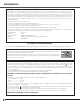
Antitheft Alarm Function How to Use the Antitheft Alarm Function Antitheft alarm function is provided to prevent the projector from being stolen. When this function is set to “On,” the alarm rings as an unauthorized person tries to move the projector. To activate the Alarm function for the first time after purchase, you must turn on the power once. ✔Note: •This function is not a guarantee against stealing.
Antitheft Alarm Function Other settings Change the PIN code 1 Press the F button and enter the four-digit PIN code number within about 10 seconds. The ALARM indicator blinks red for a few seconds and a high-pitched confirmation sound is produced. 2 While the indicator is blinking, enter a new PIN code, then you will hear a high-pitched confirmation sound and the ALARM indicator is turned off. Indicator ALARM indicator Terminal When you enter an incorrect PIN code, you will hear a low-pitched sound.
Antitheft Alarm Function Charge the built-in battery pack As long as the AC power cord is connected, the built-in battery for Alarm function is being charged at all times. While charging the battery, “Charging” is displayed in the menu. The “Charging” appears dimmed when the battery is fully charged or if charging malfunction occurs. Screw Replace the rechargeable battery pack Use only the specified battery for this projector. Using other types of battery may cause accident or fire hazard.
Antitheft Alarm Function SAFETY Precautions for SANYO Ni-MH BATTERY PACK Observe the following precautions when handling the built-in battery pack of the projector: ● MAKE SURE THAT THE BATTERY PACK IS INSTALLED IN THE PROJECTOR WHEN RECHARGING. USING THE CHARGERS OTHER THAN THE PROJECTOR MAY CAUSE EXPLOSION OR A FIRE. ● The rechargeable battery pack is for use exclusively with this projector. Do not use in other products or this may cause accident. ● Do not throw the battery into fire or heat it.
Maintenance and Cleaning Warning Indicator The WARNING indicator shows the state of the function which protects the projector. Check the state of the WARNING indicator and the POWER indicator to take proper maintenance. The projector is shut down and the WARNING indicator is blinking red. Indicators WARNING blinking red When the temperature inside the projector reaches a certain level, the projector is automatically shut down to avoid overheating.
Maintenance and Cleaning Cleaning the Air Filter The air filter prevents dust from accumulating on the surface of the optical elements inside the projector. Should the air filter become clogged with dust particles, it will reduce cooling fans’ effectiveness and may result in a buildup of internal heat and adversely affects the life of the projector. Clean the air filter by following the steps below. 1 Turn off the projector, and unplug the AC power cord from the AC outlet.
Maintenance and Cleaning Cleaning the Projection Window CAUTION This projector is equipped with a projection window. Do not rub the projection window with a hard fiber cloth or hit it with a something hard to prevent the projection window from scratching. Do not use a chemical cleaner (liquid and solid) to avoid deteriorating the projection window. Unplug the AC power cord before cleaning. First, remove the dust with a blower. Then gently wipe the projection window surface.
Maintenance and Cleaning Lamp Replacement When the projection lamp of the projector reaches its end of life, the Lamp replacement icon appears on the screen and LAMP REPLACE indicator lights yellow. Replace the lamp with a new one promptly. The timing when the LAMP REPLACE indicator should light is depending on the lamp mode.
Maintenance and Cleaning Lamp Replacement Counter Be sure to reset the Lamp replacement counter after the lamp is replaced. When the Lamp replacement counter is reset, the LAMP REPLACE indicator stops lighting. 1 Turn the projector on and press the MENU button to display the On-Screen Menu. Use the Point 7 8 buttons to move the red frame pointer to the Setting Menu icon. 2 Use the Point ed buttons to move the red frame pointer to Lamp counter and then press the SELECT button.
Appendix Troubleshooting Before calling your dealer or service center for assistance, check the items below once again. – Make sure you have properly connected the projector to peripheral equipment as described on pages 16-18. – Make sure all equipment is connected to the AC outlet and the power is turned on. – When you operate the projector with a computer and it does not project an image, restart the computer. Problem: – Solutions No power – Plug the power cord of the projector into the AC outlet.
Appendix Image is out of focus. – Adjust focus of the projector (see page 24). – Provide proper distance between the projector and the projection screen (see page 14). – Check the projection window to see if it needs cleaning (see page 62). – Moving the projector from a cool to warm place may result in moisture condensation on the projection lens. If this occurs, leave the projector off and wait until condensation evaporates.
Appendix – Check the batteries. – Make sure no obstruction is between the projector and the remote control. – Make sure you are not too far from the projector when using the remote The Remote Control does not work. control. Maximum operating range is 11.5’ (3.5 m). – Make sure the code of the remote control is conformed to that of the projector (see page 51). – Unlock the Key lock function for the remote control. (see page 51). Indicators blinks or lights. Alarm does not stop ringing.
Appendix Menu Tree Computer Input/Video Input Input Computer 1 RGB Go to System (1) RGB( Scart ) Quit Computer 2 Go to System (1) Video Auto Go to System (2) or (3) Video Go to System (3) S-Video Go to System (3) Component Go to System (2) Quit Wired See owner’s manual “Network Setup and Operation.” Wireless See owner’s manual “Network Setup and Operation.
Appendix Setting Setting Video Input System (2) Auto 1080i 1035i 720p 575p 480p 575i 480i System (3) Image Select Image Adjust 16 languages provided. Quit Zoom Reset / Store 1 / Store 2 Keystone Uniformity Adj. Store / Reset Reset / Store 1 / Store 2 Blue back On / Off Display Logo Off/ Countdown off / On Logo select Off Default User Capture Yes / No Logo PIN code lock Logo PIN code entry On / Off Auto PAL SECAM NTSC NTSC 4.
Appendix Indicators and Projector Condition Check the indicators for projector condition. For Alarm indicator, see pages 56-57. Indicators POWER WARNING red/green red Projector Condition LAMP REPLACE yellow The projector is off. (The AC power cord is unplugged.) ✽ ✽ The projector is preparing for stand-by or the projection lamp is being cooled down. The projector cannot be turned on until cooling is completed. The projector is ready to be turned on with the ON/STAND-BY button.
Appendix Compatible Computer Specifications Basically this projector can accept the signal from all computers with the V-, H-Frequency mentioned below and less than 140 MHz of Dot Clock. When these modes are selected, PC adjustment can be limited.
Appendix Technical Specifications Mechanical Information Projector Type Dimensions (W x H x D) Net Weight Feet Adjustment Multi-media Projector 14.72” x 7.75” x 19.49” (374.0 mm x 196.8 mm x 495.0 mm) (Not including protrusions) 16.9 lbs (7.7 kg) 0˚ to 1.0˚ Panel Resolution LCD Panel System Panel Resolution Number of Pixels 0.
Appendix Accessories Owner’s Manual (CD-ROM) Quick Reference Guide AC Power Cord Remote Control and Batteries VGA Cable PIN Code Label Alarm Label Stand Ferrite Core Cable Tie Network Application (CD-ROM) ● The specifications are subject to change without notice. ● LCD panels are manufactured to the highest possible standards. Even though 99.99% of the pixels are effective, a tiny fraction of the pixels (0.01% or less) may be ineffective by the characteristics of the LCD panels.
Appendix Configurations of Terminals COMPUTER INPUT / MONITOR OUTPUT TERMINAL (ANALOG) Terminal : Analog RGB (Mini D-sub 15 pin) 11 6 12 7 8 2 1 13 14 10 9 3 1 2 3 4 5 6 7 8 15 4 5 Red Input / Output Green Input / Output Blue Input / Output 9 10 11 12 13 14 15 ----Ground (Horiz.sync.) Ground (Red) Ground (Green) Ground (Blue) 5V / ----Ground (Vert.sync.) Ground / ----DDC data / ----Horiz. sync. Input/Output (Composite H/V sync.) Vert. sync.
Appendix PIN Code Number Memo Write down the PIN code number in the column below and keep it with this manual securely. If you forgot or lost the number and unable to operate the projector, contact the service station. PIN Code Lock No. Factory default set No: 1 2 3 4* Logo PIN Code Lock No. Factory default set No: 4 3 2 1* Alarm PIN Code No. Factory default set No: 1 1 1 1* *Should the four-digit number be changed, the factory set number will be invalid. While the projector is locked with the PIN code.
Appendix PJ Link Notice This projector is compliant with PJLink Standard Class 1 of JBMIA (Japan Business Machine and Information System Industries Association). The projector supports all commands defined by PJLink Class 1 and is verified conformance with PJLink Standard Class 1. For PJ Link password, see page 49 on the owner’s manual “Network Set-up and Operation.
KV7A SANYO Electric Co., Ltd.