
Projector User Manual

10
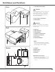
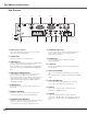
Part Names and Functions
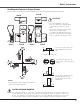
Side Terminal
q
w
e
r
o
!0
!2!1
!0 S-VIDEO IN
Connect the S-VIDEO output from video equipment to
this jack (p.17).
!4 AUDIO IN
Connect the audio output from video equipment
connected to
t, !0 or !3 to this jack. [When the audio
output is monaural, connect it to L (MONO) jack (pp.17-
18).
!2 AUDIO IN COMPUTER
Connect the audio output (stereo) from a computer
connected to e or r to this jack (pp.16, 18).
!3 VIDEO IN
Connect the composite video output from video
equipment to VIDEO jack (p.17).
r COMPUTER IN 2/MONITOR OUT
This terminal is switchable and can be used for input
from a computer or output to the other monitor.
Set the terminal up as either Computer input or Monitor
output properly. [Used for Monitor out, this terminal
outputs only incoming signal from COMPUTER IN 1
terminal (pp. 16, 49)].
!1 AUDIO OUT(VARIABLE)
Connect an external audio amplifier to this jack (pp.16-
18).
This terminal outputs sound from AUDIO IN terminal (!2
or !4).
w SERVICE PORT
This jack is used to service the projector.
e COMPUTER IN 1
Connect output signal from a computer, or RGB scart 21-
pin video output to this terminal (pp.16, 18).
When the cable is of the longer variety, it is advisable to
use this terminal and not COMPUTER IN 2/MONITOR
O U T.
!3
o ALARM buttons
Use these buttons when setting up the Alarm
function (pp.56-57).
t COMPONENT IN
Connect the component video output signal to these
jacks (p.18).
!4
q LAN Connection Terminal
Connect the LAN cable (refer to the owner’s manual
“Network Set-up and Operation”).
i SD MEMORY CARD SLOT
Insert the SD memory card (not supplied) for Memory
viewer operation (refer to the owner’s manual of
Memory Viewer function).
u SD MEMORY CARD INDICATOR
Display the status of SD memory card. When inserting
SD memory card, the indicator lights, and when
removing SD memory card, the indicator turns off.
y WIRELESS INDICATOR
Display the status of wireless network. Refer to the
owner’s manual “Network Set-up and Operation”.
t
y
u
i