Multimedia Projector MODEL PLC-HP7000L Projection lens is optional. Owner’s Manual Network Supported Refer to the Owner's Manual below for details about network function.
Features and Design This Multimedia Projector is designed with most advanced technology for portability, durability, and ease of use. This projector utilizes built-in multimedia features, a palette of 1.07 billion colors, and matrix liquid crystal display (LCD) technology. This projector employs Full HD LCD panels with 1,920x1,080 pixels, allowing it to project high resolution signals at their native resolution.
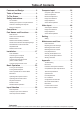
Table of Contents Features and Design . . . . . . . . . . . . . 2 Table of Contents . . . . . . . . . . . . . . . 3 To The Owner . . . . . . . . . . . . . . . . . . . 4 Safety Instructions . . . . . . . . . . . . . . 5 Computer Input . . . . . . . . . . . . . . . .
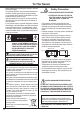
To The Owner Before installing and operating the projector, read this manual thoroughly. The projector provides many convenient features and functions. Operating the projector properly enables you to manage those features and maintains it in good condition for many years to come. Improper operation may result in not only shortening the product life, but also malfunctions, fire hazard, or other accidents.
Safety Instructions All the safety and operating instructions should be read before the product is operated. Read all of the instructions mentioned here and retain them for later use. Unplug this projector from AC power supply before cleaning. Do not use liquid or aerosol cleaners. Use a damp cloth for cleaning. Follow all warnings and instructions marked on the projector.
Safety Instructions Air Circulation Openings in the cabinet are provided for ventilation. To ensure reliable operation of the product and to protect it from overheating, these openings must not be blocked or covered. CAUTION Hot air is exhausted from the exhaust vent. When using or installing the projector, the following precautions should be taken. – D o not put any flammable object or spray can near the projector, as hot air is exhausted from the air vents.
Safety Instructions Installing the Projector in Proper Directions Use the projector properly in specified positions. Improper positioning may shorten the lamp life and result in severe accidents or fire hazard. This projector can project the picture in upward, downward, or inclined position in perpendicular direction to the horizontal plane. When installing the projector in downwardly inclined position, install the projector bottom side up.
Safety Instructions Moving the Projector Use the handle grip when moving the projector. Retract the adjustable feet to prevent damage to the lens and cabinet when carrying. When this projector is not in use for an extended period, put it into a suitable case to protect the projector. CAUTION IN CARRYING OR TRANSPORTING THE PROJECTOR – Do not drop or bump the projector, otherwise damages or malfunctions may result. – When carrying the projector, use a suitable carrying case.
Compliance Federal Communications Commission Notice This equipment has been tested and found to comply with the limits for a Class A digital device, pursuant to Part 15 of FCC Rules. These limits are designed to provide reasonable protection against harmful interference when the equipment is operated in a commercial environment.
Part Names and Functions Front ② ① ④ ⑤ Back ⑥ ⑦ ⑫ ⑪ ① Indicators ② Top Cover ③ Top Cover Release Button ④ Infrared Remote Receiver (Front) ⑤ Projection Lens (optional) ⑥ Light-Block Sheet ⑦ Adjustable Feet ⑧ Air Intake Vent ⑨ Filter Cover ⑩ Lamp Cover ⑪ Exhaust Vent ③ ⑧ ⑨ ⑩ CAUTION Hot air is exhausted from the exhaust vent. Do not put heat-sensitive objects near this side.
Part Names and Functions Rear Terminal ① ② ⑥ ⑦ ③ ⑧ ④ ⑨ ① HDMI TERMINAL Connect the HDMI signal from video equipment or the DVI signal from computer to this terminal (pp.20, 21). i s registered trademarks of HDMI Licensing, LLC. ② COMPUTER INPUT TERMINAL (ANALOG) Connect the computer (or RGB scart) output signal to this terminal (pp.20, 21). ③ COMPUTER INPUT TERMINAL (DIGITAL) Connect the computer output digital signal to this terminal.
Part Names and Functions Side Control and Indicators Side Control Indicators (on the top panel) ① ⑧ ② ⑦ ③ ⑥ ④ ⑨ ⑩ ⑪ ⑤ ① ON/STAND-BY button Turn the projector on or off (pp.23–24). ② INPUT button Select an input source (pp.32–34). ⑫ ⑧ POWER indicator – Light when in stand-by mode and during operations. – Blink in the Power management mode (p.63). ③ MENU button Open or close the On-Screen Menu (p.25). ⑨ LAMP/SHUTTER indicator Light red during operations.
Part Names and Functions Remote Control ② ① ③ ④ ⑫ ⑤ ⑪ ⑩ ⑥ ⑨ ⑦ ⑧ ① STAND-BY button Turn the projector off (p.24). ② Signal Emission indicator Light red while a signal is being sent from the remote control to the projector. ③ ON button Turn the projector on (p.23). ④ SHUTTER button Close and open up the built-in shutter (pp.27, 28). ⑤ MENU button Open or close the On-Screen Menu (p.25). ⑥ Point ▲▼◄► buttons – Select an item or adjust the value in the On-Screen Menu (p.25).
Part Names and Functions Remote Control ㉙ ㉘ ㉗ ⑬ ⑭ ㉖ ⑮ ㉕ ⑯ ㉚ For PIN code and remote control code. ㉔ ㉓ ㉒ ㉑ ⑰ ⑱ ⑲ ⑳ ⑬ P-TIMER button Operate the P-timer function (pp.29, 64). ㉒ FOCUS buttons Adjust the focus (p.28). ⑭ IMAGE SEL. button Operate the image selection function (pp.39, 47). ㉓ INFO. button Display the input source information (p.28). ⑮ FREEZE button Freeze the picture on the screen (p.29). ㉔ KEYSTONE button Correct keystone distortion (pp.30, 45, 52).
Part Names and Functions Remote Control Battery Installation 1 Open the battery compartment lid. 2 Install new batteries into the compartment. 3 Replace the compartment lid. Two AAA size batteries For correct polarity (+ and –), be sure battery terminals are in contact with pins in the compartment. To ensure safe operation, please observe the following precautions : ● Use two (2) AAA or LR03 type alkaline batteries. ● Always replace batteries in sets.
Part Names and Functions Remote Control Code The eight different remote control codes (Code 1–Code 8) are assigned to this projector. Switching the remote control codes prevents interference from other remote controls when several projectors or video equipment next to each other are being operated at the same time. Change the remote control code for the projector first before changing that for the remote control. See “Remote control” in the Setting Menu on page 62.
Installation Lens Installation When replacing the lens or using an optional lens, install the lens by following the instructions below. Ask the sales dealer for detailed information of the optional lens specifications. Removing the lens 1 Shift the lens to the center position by using the Lens shift function (p. 27). 2 Turn off the projector and unplug the AC power cord. 3 While pressing the top cover release button on the top cover, slide the top cover toward front to remove it.
Installation Attaching the lens to the projector 1 Turn off the projector and unplug the AC power cord. 2 Fit the lens to the projector. Make sure that the lens is fully inserted to the projector. 3 Push the Lens Lock Lever downward. Make sure that the lens is properly locked. 4 Slide the light-block sheet in the groove to mount. While pressing the top cover release button on the top cover, slide the top cover back to the projector.
Installation Focus correction Focus adjustment When the lens is attached to the projector and images are being projected onto the screen, the peripheral focus may be out of focus in some localized areas. If this happens, insert the one, of three sizes of spacers, in between the Lens Attachment and the lens to adjust the focus. Inserting the Spacer corrects the distance on the Lens Adjustment and improves the diagonal focus. The corrected distance is determined by the thickness of the used spacers.
Installation Connecting to a Computer (Digital and Analog RGB) Cables used for connection ( = Cables not supplied with this projector.) • VGA Cable • BNC cable • DVI-Digital cable • Serial Cross cable • HDMI-DVI cable • USB cable USB port Monitor Output BNC cable USB cable USB G B R H/V V DVI Output HDMIDVI cable HDMI Unplug the power cords of both the projector and external equipment from the AC outlet before connecting cables.
Installation Connecting to Video Equipment (Video, S-video, HDMI) Cables used for connection ( = Cables not supplied with this projector.) • Video cable (RCA x 1 or RCA x 3) • BNC cable (BNC x 1 or BNC x 3) • S-video cable Monitor Out Signal Table • HDMI cable Input Terminal Monitor Out • VGA Cable RGB (PC analog) YES (One cable is supplied.
Installation Connecting the AC Power Cord This projector uses nominal input voltages of 100–240 V AC and it automatically selects the correct input voltage. It is designed to work with single-phase power systems having a grounded neutral conductor. To reduce the risk of electrical shock, do not plug into any other type of power system. If you are not sure of the type of power being supplied, consult your authorized dealer or service center.
Basic Operation Turning On the Projector 1 Complete peripheral connections (with a computer, VCR, etc.) before turning on the projector. 2 Connect the projector’s AC power cord into an AC outlet. The LAMP/SHUTTER indicator lights red and the POWER indicator lights green. 3 Press the ON/STAND-BY button on the side control or the ON button on the remote control. The LAMP/ SHUTTER indicator dims and the cooling fans start to operate. The preparation display appears on the screen and the countdown starts.
Basic Operation What is PIN code? PIN (Personal Identification Number) code is a security code that allows the person who knows it to operate the projector. Setting a PIN code prevents unauthorized use of the projector. A PIN code consists of a four-digit number. Refer to the PIN code lock function in the Setting Menu on pages 65-66 for locking operation of the projector with your PIN code. CAUTION ON HANDLING PIN CODE If you forget your PIN code, the projector can no longer be started.
Basic Operation How to Operate the On-Screen Menu The projector can be adjusted or set via the On-Screen Menu. The menu has a hierarchical structure, with a main menu that is divided into submenus, which are further divided into other submenus. For each adjustment and setting procedure, refer to respective sections in this manual. 1 Press the MENU button on the side control or the remote control to display the On-Screen Menu. 2 Use the Point ▲▼ buttons to highlight or select a main menu item.
Basic Operation Main Menu For detailed functions of each menu, see “Menu Tree” on pages 81-83. Main Menu Sub-Menu Input Used to select an input source (Input 1, Input 2, Input 3 or Network) (p.32). Note: Network will not be displayed when optional PJ-Net Organizer is not attached. PC adjust Used to adjust the parameters to match with the input signal format (pp.36-38).
Basic Operation Operating with Projector Control Lens Operation Side Control The following lens operation can be made with the LENS button on the side control. LENS button Press the LENS button to enter each lens operation mode. The selected adjustment display appears on the screen. Zoom → Focus → Lens Shift → …… POINT buttons Zoom Adjustment Display Zoom on the screen. Use the Point ▲▼ buttons to zoom in and out the image. SHUTTER button Focus Adjustment Display Focus on the screen.
Basic Operation Operating with Remote Control Using the remote control for some frequently used operations is advisable. Just pressing one of the buttons enables you to make the desired operation quickly without calling up the On-Screen Menu. SHUTTER button See pages 27, 67 for details. IMAGE SEL. button Press the IMAGE SEL. button on the remote control, the last stored image will be displayed on the screen for about 4 seconds. For its further functions, see pages 39 and 47 for details. D.
Basic Operation MOUSE POINTER button Move the pointer on the screen with this button. Remote Control POINTER button Press POINTER button on the remote control to display the Pointer on the screen. (see pages 31, 64) P-TIMER button Press the P-TIMER button on the remote control to operate the Count up/Count down function. See page 64 for details of Setting for the P-timer function. To stop the count time, press the P-TIMER button.
Basic Operation Keystone Correction If a projected picture still has keystone distortion after pressing the AUTO PC button on the remote control, correct the image manually as follows: Press the KEYSTONE button on the remote control to switch the Standard (for Vertical/Horizontal) /Corner correction adjustment. The Standard or Corner correction adjustment dialog box appears. Use the Point ▲▼◄► buttons to correct the Standard or Corner distortion.
Basic Operation Pointer Function You can move the Pointer of the projector with the remote control to emphasize a part of the projected image. 1 Press the POINTER button to activate the Pointer function. MOUSE POINTER button 2 Use the MOUSE POINTER button to move the Pointer. POINTER button 3 To cancel the Pointer function, press the POINTER button again or press any other button. Finger Arrow Dot Note: You can choose the pattern of Pointer (Dot/Arrow/ Finger) in the Setting Menu (p.
Input Selection Direct Operation Side Control/Remote Control Operation Remote Control Side Control INPUT button* INPUT button* * Only the Input button function is set Mode 1 in the Setting menu, the INPUT button is used for switching input source. (p.53) The input source changes each time you press the INPUT button on the side control or the remote control as follows: Input 1→ Input 2→ Input 3 → ...
Input Selection Computer Input Source Selection Menu Operation 1 Press the MENU button to display the On-Screen Menu. Use the Point ▲▼ buttons to select Input and then press the Point ► or the SELECT button. 2 Use the Point ▲▼ buttons to select the desired input and then press the Point ► button to access the submenu items. 3 Use the Point ▲▼ buttons to select the desired source and then press the SELECT button.
Input Selection Video Input Source Selection Menu Operation 1 Press the MENU button to display the On-Screen 2 3 Menu. Use the Point ▲▼ buttons to select Input and then press the Point ► or the SELECT button. Use the Point ▲▼ buttons to select the desired input and then press the Point ► button to access the submenu items. Use the Point ▲▼ buttons to select the desired source and then press the SELECT button.
Computer Input Computer System Selection Automatic Multi-Scan System This projector automatically tunes to various types of computers with its Multi-scan system and Auto PC adjustment. If a computer is selected as a signal source, this projector automatically detects the signal format and tunes to project a proper image without any additional settings.
Computer Input Auto PC Adjustment Auto PC Adjustment function is provided to automatically adjust Fine sync, Total dots, Position H and Position V to conform to your computer. Direct Operation Remote Control The Auto PC adjustment function can be operated directly by pressing the AUTO PC button on the remote control. AUTO PC button Menu Operation Auto PC adj. 1 Press the MENU button to display the On-Screen PC adjust Menu Menu.
Computer Input Manual PC Adjustment Some computers employ special signal formats which may not be tuned by Multi-Scan system of this projector. Manual PC Adjustment enables you to precisely adjust several parameters to match those special signal formats. The projector has 10 independent memory areas to store those parameters manually adjusted. It allows you to recall the setting for a specific computer. 1 2 Press the MENU button to display the On-Screen Menu.
Computer Input Reset To reset the adjusted data, select Reset and press the SELECT button. A confirmation box appears and then select Yes. All adjustments will return to their previous figures. Mode free To clear the stored data, select Mode free and then press the Point ► or the SELECT button. Move the highlight to the Mode that you want to clear and then press the SELECT button. Mode free Store To store the adjusted data, select Store and then press the Point ► or the SELECT button.
Computer Input Image Level Selection Direct Operation The Image Selection function can be operated directly by pressing the IMAGE SEL. button on the remote control. the last stored image will be displayed on the screen for about 4 seconds. IMAGE SEL. button Menu Operation 1 Press the MENU button to display the On-Screen Menu. Use the Point ▲▼ buttons to select Image select and then press the Point ► or the SELECT button. The factory default setting is Standard.
Computer Input Image Adjustment 1 Press the MENU button to display the On-Screen Menu. Use the Point ▲▼ buttons to select Image adjust and then press the Point ► or the SELECT button. Image adjust Menu 2 Use the Point ▲▼ buttons to select the desired item and then press the SELECT button to display the adjustment dialog box. Use the Point ◄► buttons to adjust the setting value. Contrast Press the Point ◄ button to decrease the contrast; press the Point ► button to increase the contrast (from 0 to 63).
Computer Input MENU Return to the IMAGE ADJUST Menu. Any settings that have been changed will not be stored. To store the changed settings, be sure to select LIST and go to the COLOR MANAGEMENT LIST. COLOR SELECTION MODE Level and phase adjustment palette. Gamma adjustment palette. 4 In the COLOR MANAGEMENT LIST, the adjusted color data are checkmarked. You can decide whether or not to apply the adjusted color data in the list to the projected image (see below).
Computer Input Offset (Red/Green/Blue) Press the Point ◄ button to lighten red/green/blue tone of the black level of an image; press the Point ► button to deepen red/green/blue tone of the black level of an image. Auto picture control Use the Point ◄► buttons to select the desired Auto picture control option (Off, L1 or L2). Off ��������������� Auto picture control OFF position. L1 ���������������� Auto picture control LEVEL 1 position. L2 ���������������� Auto picture control LEVEL 2 position.
Computer Input Screen Size Adjustment Select the desired screen size that conforms to the input signal source. 1 Press the MENU button to display the On-Screen Menu. Use the Point ▲▼ buttons to select Screen and then press the Point ► or the SELECT button. 2 Use the Point ▲▼ buttons select the desired item and then press the SELECT button. SCREEN MENU Normal Provide the image within a screen size keeping its original aspect ratio. Full Provide the image to fit full screen size.
Computer Input Custom adj. Adjust the screen scale and position manually with this function. Press the Point ► button or the SELECT button at Custom adj. and Custom adj. is displayed on the screen, you can use the Point ▲▼ buttons to choose the item you want to adjust. Scale H/V �������� Adjust the Horizontal/Vertical screen scale. H&V ����������������� When set to On, the aspect ratio is fixed. Scale V appears dim and becomes unavailable.
Computer Input Keystone This function is used to adjust keystone distortion of the projected image. Use the Point ▲▼ buttons to choose the item you want to adjust. Keystone Standard Adjust the Horizontal/Vertical keystone distortion of the projected image. Corner correction Adjust the corner distortion of the projected image. Corner pattern Choose a Corner pattern mode among Red, White, Blue, and Off. Store Store..... Keep the keystone correction even when the AC power cord is unplugged.
Video Input Video System Selection 1 Press the MENU button to display the On-Screen Menu. Use the Point ▲▼ buttons to select Input and then press the Point ► or the SELECT button. 2 Use the Point ▲▼ buttons to select System and then press the Point ► or the SELECT button. 3 Use the Point ▲▼ buttons to select the desired system and then press the SELECT button.
Video Input Image Level Selection Direct Operation The Image Selection function can be operated directly by pressing the IMAGE SEL. button on the remote control. the last stored image will be displayed on the screen for about 4 seconds. IMAGE SEL. button Menu Operation 1 Press the MENU button to display the On-Screen Menu. Use the Point ▲▼ buttons to select Image select and then press the Point ► or the SELECT button.
Video Input Image Adjustment 1 Press the MENU button to display the On-Screen Menu. Use the Point ▲▼ buttons to select Image adjust and then press the Point ► or the SELECT button. 2 Use the Point ▲▼ buttons to select the desired item and then press the SELECT button to display the adjustment dialog box. Use the Point ◄► buttons to adjust the setting value. Image adjust Menu Contrast Press the Point ◄ button to decrease the contrast; press the Point ► button to increase the contrast (from 0 to 63).
Video Input Offset (Red/Green/Blue) Press the Point ◄ button to lighten red/green/blue tone of the black level of an image; press the Point ► button to deepen red/green/blue tone of the black level of an image (from 0 to 63). Auto picture control Use the Point ◄► buttons to select the desired Auto picture control option (Off, L1 or L2). Off ��������������� Auto picture control OFF position. L1 ���������������� Auto picture control LEVEL 1 position.
Video Input Noise reduction Noise interference on the screen can be reduced. Press the Point ◄► buttons to change the noise reduction mode. Off ������������� Noise reduction mode is Off. On ������������� Noise reduction mode is On. Progressive An interlaced video signal can be displayed in progressive mode. Press the Point ◄► buttons to change the progressive scan mode. Off ������������� Progressive scan mode is Off. On ������������� Progressive scan mode is On.
Video Input Screen Size Adjustment 1 Press the MENU button to display the On-Screen Menu. Use the Point ▲▼ buttons to select Screen and then press the Point ► or the SELECT button. 2 Use the Point ▲▼ buttons to select the desired item and then press the SELECT button. Normal Provide the image within a screen size keeping its original aspect ratio. Full Provide the image to fit full screen size. Wide (16:9) Provide the image at the 16:9 wide screen ratio. Custom adj.
Video Input Keystone This function is used to adjust keystone distortion of the projected image. Use the Point ▲▼ buttons to choose the item you want to adjust. Keystone Standard Adjust the Horizontal/Vertical keystone distortion of the projected image. Corner correction Adjust the corner distortion of the projected image. Corner pattern Choose a Corner pattern mode among Red, White, Blue, and Off. Store Store.... Keep the keystone correction even when the AC power cord is unplugged.
Setting Setting This projector has a Setting menu that allows you to set up the other various functions described below. Setting Menu 1 Press the MENU button to display the On-Screen 2 Menu. Press the Point ▲▼ buttons to select Setting and press the Point ► or the SELECT button to access the submenu items. Use the Point ▲▼ buttons to select the desired item and then press the Point ► or the SELECT button to access the selected item.
Setting Display This function decides whether to display On-Screen Displays. On ������������������������� Show all the On-Screen displays. Use this function when you want to project images after the lamp becomes bright enough. The factory default setting is in this option. Countdown Off ���� Show the input image instead of the countdown when turning on the projector. Use this function when you want to project the image as early as possible even when the lamp is not bright enough.
Setting Capture This function enables you to capture an image being projected to use it for a starting-up display or interval of presentations. Select Capture and press the SELECT button. A confirmation box appears and select Yes to capture the projected image. Capture After capturing the projected image, go to the Logo select function and set it to User. Then the captured image will be displayed the next time you turn on the projector.
Setting Enter a Logo PIN code Use the Point ▲▼ buttons on the side control or Number buttons on the remote control to enter a number. When using side control Use the Point ▲▼ buttons on the side control to select a number. Press the Point ► button to fix the number and move the red frame pointer to the next box. The number changes to . If you fix an incorrect number, use the Point ◄ button to move the pointer to the number you want to correct, and then enter the correct number.
Setting Picture in Picture This function is used to project two images simultaneously by placing a separate small sub screen within or next to the main screen. Use the Point ▲▼ buttons to select Picture in Picture and then press the SELECT button to display a dialog box. You can also display the dialog box by pressing and holding the PIP button on the remote control for more than 3 seconds.
Setting Frame lock Set the Frame Lock to Main picture or Sub picture. Reset Press the SELECT button at Reset to display a confirmation box. To reset, press the SELECT button at Yes. Mode free Delete the data stored in the Mode and return to Free. Use the Point ▲▼ buttons to select Mode free and press the SELECT button to show the Where to free? dialog box. Move the highlight to one of the mode (User 1 - 5) which you want to delete and press the SELECT button. Then the confirmation box appears.
Setting Color matching When displaying multiple screens, eliminates the difference in color between the images that are projected from the projectors. When multiple sets are used simultaneously, this projector allows the user to correct the difference of colors among the sets. Use the Point ▲▼ buttons to select Color matching and then press the SELECT button to display a dialog box. Use the Point ▲▼◄► buttons to adjust the setting value. Color matching......
Setting Advanced color matching Measured Information ..... When selecting Measured Information, the window shown right appears. Current image level is shown. To go back to the Advanced color matting window, press any key. Advanced color matching..... Press the POINT ▲▼ buttons to switch between On and Off. Selecting On displays the values which link to the Color Match values. Measured . ............. Displays the measured values of Red, Green, and Blue. Target . ...................
Setting Lamp control Lamp control This function allows you to change brightness of the screen. Auto �������� Brightness according to the input signal. Normal ���� Normal brightness. Eco 1 ������ Lower brightness and decrease of fan speed. Lower brightness reduces the lamp power consumption and extends the lamp life. Eco 2 ������ Lower brightness and increase of fan speed. Lower brightness reduces the lamp power consumption and extends the lamp life.
Setting Simple mode This function decides whether to activate the simple mode. Off ������ Simple mode function is off. On ������ Only the simple mode buttons are active. Note: Warning icon and Simple mode : On message appear on the screen for about 4 seconds when press the button which is not the simple mode button.
Setting Power management For reducing power consumption as well as maintaining the lamp life, the Power management function turns off the projection lamp when the projector is not operated for a certain period. Select one of the following options: Ready 1 ����������� When the lamp has been fully cooled down, the POWER indicator changes to green blinking.
Setting Pointer You can emphasize a part of the projected image with this function. Use the Point ▲▼ buttons to select a pattern of the Pointer (Dot, Arrow or Finger). (p.31) P-TIMER P-timer display. P-timer This function allows you to change the presentation of the P-timer and execute it.
Setting Security (Key lock and PIN code lock) This function allows you to use the Key lock and PIN code lock function to set the security for the projector operation. Key lock Key lock This function locks the side control and remote control buttons to prevent operation by unauthorized persons. …Unlocked. …Lock the operation of the side control. To unlock, use the remote control. … Lock the operation of the remote control. To unlock, use the side control.
Setting Enter a PIN code Use the Point ▲▼ buttons on the side control or Number buttons on the remote control to enter a number. When using side control Use the Point ▲▼ buttons on the side control to select a number. Press the Point ► button to fix the number and move the red frame pointer to the next box. The number changes to . If you fix an incorrect number, use the Point ◄ button to move the pointer to the number you want to correct, and then enter the correct number.
Setting Shutter Shutter function is available to block out light to the screen, so that the screen can be used for the other presenters. Protection Prohibit the shutter operation from the remote control and the projector's side control. Shutter …………… Permit the shutter operation from both the remote control and the projector's side control. …………… Prohibit the shutter operation from the remote control. …………… Prohibit the shutter operation from the side control.
Setting Closed caption Closed caption is a printed version of the program sound or other information displayed on the screen. If the input signal contains Closed captions, you can turn on the feature and switch the channels. Press the Point ▲▼ buttons to select Off, CC1, CC2, CC3 or CC4. If the Closed caption is not clear, you can change the text from Color to White. Closed caption Note: The Closed caption is available only under the situation below.
Setting Lamp counter Be sure to reset the Lamp replacement counter after the lamp is replaced. (p. 65) Press the Point ▲▼ buttons to choose the Lamp counter function and then press the Point ► or the SELECT button to access the submenu items. Lamp counter reset Lamp counter ����������������� This item shows the total accumulated time of the lamp usage.
Setting Filter counter This function is used to set a frequency for the filter replacement. Filter counter Use the Point ▲▼ buttons to select Filter counter and then press the Point ► or the SELECT button to access the submenu items. Filter counter…… Show the total accumulated time of the filter use timer setting. Timer…………… To set a timer, when the projector reaches the time, the Filter replacement icon (Fig.
Maintenance and Care Filter Instructions Filter prevents dust from accumulating on the optical elements inside the projector. Should the filter becomes clogged with dust particles, it will reduce cooling fans’ effectiveness and may result in internal heat buildup and adversely affect the life of the projector. This projector has an electrically operated filter which helps you to replace the filter easily.
Maintenance and Care Replacing the Filter Cartridge 1 Turn off the projector, and unplug the AC power cord from the AC outlet. 2 First, clean up the dust on the projector and around the air vents. 3 Press ▼ downwards on the filter cover to release the latch and open the filter cover. 4 Pull out the filter cartridge. When taking out the filter cartridge, put your finger on the filter cartridge’s tab and then pull. 5 Put the new one back into the position and close the filter cover.
Maintenance and Care Resetting the Filter Counter Be sure to reset the Filter counter after replacing the filter cartridge. 1 Press the MENU button to display the On-Screen Menu. Use the Point ▲▼ buttons to select Setting and then press the Point ► or the SELECT button. 2 Use the Point ▲▼ buttons to select Filter counter and then press the SELECT button. Use the Point ▲▼ buttons to select Filter counter reset and then press the SELECT button. Filter counter Reset? appears. Select Yes to continue.
Maintenance and Care Lamp Replacement When the projection lamp of the projector reaches its end of life, the Lamp replacement icon appears on the screen and LAMP REPLACE indicator lights orange. Replace the lamp with a new one promptly. The timing when the LAMP REPLACE indicator should light is depending on the lamp mode. Filter cover Top Panel Lamp cover Lamp replacement icon Screw LAMP REPLACE indicator Note: The Lamp replacement icon will not appear when the Display function is set to Off (p.
Maintenance and Care LAMP HANDLING PRECAUTIONS This projector uses a high-pressure lamp which must be handled carefully and properly. Improper handling may result in accidents, injury, or create a fire hazard. ● Lamp lifetime may differ from lamp to lamp and according to the environment of use. There is no guarantee of the same lifetime for each lamp. Some lamps may fail or terminate their lifetime in a shorter period of time than other similar lamps.
Maintenance and Care Cleaning the Projection Lens Unplug the AC power cord before cleaning. Gently wipe the projection lens with a cleaning cloth that contains a small amount of non-abrasive camera lens cleaner, or use a lens cleaning paper or commercially available air blower to clean the lens. Avoid using an excessive amount of cleaner. Abrasive cleaners, solvents, or other harsh chemicals might scratch the surface of the lens. Cleaning the Projector Cabinet Unplug the AC power cord before cleaning.
Maintenance and Care Warning Indicators The WARNING indicators show the state of the function which protects the projector. Check the state of the WARNING indicators and the POWER indicator to take proper maintenance. The projector is shut down and the WARNING TEMP. indicator is blinking red. Top Panel When the temperature inside the projector reaches a certain level, the projector will be automatically shut down to protect the inside of the projector.
Appendix Troubleshooting Before calling your dealer or service center for assistance, check the items below once again. 1. Make sure you have properly connected the projector to peripheral equipment as described on pages 20-21. 2. Check the cable connection. Make sure that all computers, video equipment, and power cords are properly connected. 3. Make sure that all power is switched on. 4. If the projector still does not produce an image, restart your computer. 5.
Appendix – Filter is out of scroll. Replace the filter cartridge with a new one promptly. (See pages 72-73) appears on the screen The image is out of focus. – Adjust the focus of the projector. – Check Projection Lens to see if it needs cleaning. Note: M oving the projector from a cool temperature location to a warm temperature location may result in moisture condensation on Projection Lens. In such cases, leave the projector OFF and wait until condensation evaporates.
Appendix – P ower management function runs by initial setting. Check “Setting” section on page 63. – If you continue to use the projector without replacing the air filter cartridge and resetting the filter counter after the filter cartridge replacement icon is displayed, the power will switch off automatically approximately 10 hours after projection starts in order to protect the optical parts.
Appendix Menu Tree Computer Input/HDMI Input/Video Input Input Input Information Input 1 RGB (PC analog) RGB (Scart) RGB (PC digital) RGB (AV HDCP) HDMI Input 2 Video Information Y, Pb/Cb,Pr/Cr RGB Input 3 Video Y, Pb/Cb,Pr/Cr S-video Network * * Network will be displayed only when an optional PJ-Net Organizer is attached. Image select Image select Computer Input SVGA1 System (1) Mode 1 Mode 10 SVGA 1 SVGA 2 SVGA 3 System displayed in the System Menu varies depending on the input signal.
Appendix HDMI Input/Video Input Screen Screen Normal Full Wide(16:9) Zoom True Custom Custom adj. Image adjust Image adjust H/V Scale On/Off H&V Position H / V Common Reset Digital zoom + Digital zoom Standard Keystone Corner correction Corner pattern Store Ceiling On/Off Rear On/Off Screen aspect Default(16:9)/16:10/4:3 Reset Video Input Contrast 0–63 Brightness 0–63 Color 0–63 Tint 0–63 Color mangement Color temp.
Appendix Computer Input/HDMI Input/Video Input Setting Setting Language Menu 12 languages provided Position Menu size Normal/Double Mode 1/Mode 2/Mode 3 On/Countdown Off/Off Blue/User/Black Logo select User Default Off Capture Yes/No Off/On Logo PIN code lock Logo PIN code change Input button Display Background Logo Picture in Picture Edge blending On/Off Left/Right Start Top/Bottom Start Left/Right Width Top/Bottom Width Black level All R/G/B On/Off Test pattern Menu off Reset Back Color matching
Appendix Direct on Pointer P-timer Security Shutter Closed caption Video delay control Lamp counter Filter counter Test pattern Factory default 84 On/Off Dot/Arrow/Finger Count up Count down Timer Start/Stop/Restart Reset Exit Key lock Off Projector Remote control PIN code lock Off/On 1/On 2 PIN code change Protection Off Remote control Projector Both Release key Any/SHUTTER Management 5 - 480 Min Closed caption Color Off/Low/Mid/High Lamp counter H Yes/No Lamp counter reset H Filter counter Off/400H
Appendix Indicators and Projector Condition Check the indicators for the projector condition. The projector is operating normally. Indicators POWER green Projector Condition LAMP WARNING WARNING LAMP/ SHUTTER REPLACE FILTER TEMP. red/blue orange orange red The projector is off. (The AC power cord is unplugged.) ❖ The projector is in stand-by mode. Press the ON/ STAND-BY button to turn on the projector. ❖ The projector is operating normally.
Appendix The projector is detecting abnormal condition. Indicators POWER green LAMP WARNING WARNING LAMP/ SHUTTER REPLACE FILTER TEMP. red/blue orange orange red ❖ The temperature inside the projector is elevated close to the abnormally high level. ❖ ❖ Projector Condition The temperature inside the projector is abnormally high. The projector cannot be turned on.
Appendix The projector is detecting abnormal condition. Indicators POWER green LAMP WARNING WARNING LAMP/ SHUTTER REPLACE FILTER TEMP. red/blue orange orange red Fig.2 F ilter replacement icon Fig.3 If the Filter counter reaches a time set in the timer setting, a Filter replacement icon (Fig.2) will appear on the screen and the WARNING FILTER indicator on the top panel will light up. Replace the filter as soon as possible.
Appendix Compatible Computer Specifications Basically this projector can accept the signal from all computers with the V- and H-Frequency mentioned below and less than 162 MHz of Dot Clock. When the input signal is Analog, refer to the chart below. ON-SCREEN DISPLAY VGA 1 VGA 2 VGA 3 VGA 4 VGA 5 VGA 6 VGA 7 MAC LC13 MAC 13 480p 575p 575i 480i 88 RESOLUTION 640x480 720x400 640x400 640x480 640x480 640x480 640x480 640x480 640x480 640x480 768x575 768x576 (Interlace) 640x480 (Interlace) H-Freq. (kHz) 31.
Appendix When the input signal is digital from HDMI/DVI-D terminal, refer to the chart below.
Appendix Technical Specifications Mechanical Information Projector Type Dimensions (W x H x D) Net Weight Feet Adjustment Multi-media Projector 14.56'' x 7.36'' x 17.32'' (370.0 mm x 187.0 mm x 439.9 mm) 35.5 lbs (16.1 kg) 0˚ to 6.5˚ Panel Resolution LCD Panel System Panel Resolution Number of Pixels 1.
Appendix Optional Parts The parts listed below are optionally available. When ordering those parts, specify the item name and Model No. to the sales dealer. Model No. Standard Zoom Lens Long Zoom Lens Ultra Long Zoom Lens Short Zoom Lens Short Fixed Lens PJ-Net Organizer Plus II : LNS-S32 : LNS-T34 : LNS-T32, LNS-T33 : LNS-W33 : LNS-W34 : POA-PN03A, POA-PN03C Lens Replacement The lens of this projector can be replaced with other optional lens.
Appendix Configurations of Terminals ANALOG/ ANALOG OUT (Mini D-sub 15 pin) Input 4 5 10 15 2 3 9 14 8 13 Red Input Green Input Blue Input No Connect Ground (Horiz.sync.) Ground (Red) Ground (Green) Ground (Blue) 9 10 11 12 13 14 15 +5V Power Ground (Vert.sync.) Ground DDC Data Horiz. sync. Input (Composite H/V sync.) Vert. sync. Input DDC Clock Output 1 Red Output 2 Green Output 3 Blue Output 4 No Connect 5 Ground (Horiz.sync.
Appendix PIN Code Number Memo Write down the PIN code number in the column below and keep it with this manual securely. If you forgot or lost the number and unable to operate the projector, contact the service center. PIN Code Lock No. Factory default set No: 1 2 3 4* Logo PIN Code Lock No. Factory default set No: 4 3 2 1* * Should the four-digit number be changed, the factory set number will be invalid. While the projector is locked with the PIN code...
Appendix Dimensions Unit: inch (mm) Screw Holes for Ceiling Mount Screw: M6 Depth: 0.393 (10.0) 7.36 (187) 4.33 (110) 4.33 (110) 5.75 (146) 13.58 (345) 17.32 (439.9) 2.05 (52) 6.5º MAX 3.94 (100) 14.57 (370) 5.20 (132) 4.13 (105) Screw Holes for Ceiling Mount Screw: M6 Depth: 0.393 (10.
Appendix List of Picture in Picture o : Picture in Picture combinations are enabled. x : Picture in Picture combinations are disabled. Note: • When the input signal(s) is/are incompatible, X mark will be displayed on the Main/Sub picture. • Depending on the frequency or signal type of PC/AV input, the display resolution may be lowered or images may not be displayed on the Main/Sub picture.
Appendix Functional Execution Command Format The command is sent from PC to the projector with the format below; 'C' [Command] 'CR' Command: two characters (refer to the command table below. - The projector decodes the command and returns the 'ACK' with the format below; 'ACK' 'CR' - When the projector can not decode the command, it returns with format below.
Appendix Status Read Command Format The command is sent from PC to the projector with the format below; 'CR' [Command] 'CR' Command: one character (refer to the command table below.
KY2AL