Multimedia Projector MODEL PLC-SE15 Owner’s Manual
TO THE OWNER Before operating this projector, read this manual thoroughly and operate the projector properly. This projector provides many convenient features and functions. Operating the projector properly enables you to manage those features and maintains it in better condition for a considerable time. Improper operation may result in not only shortening the product-life, but also malfunctions, fire hazard, or other accidents.
SAFETY INSTRUCTIONS All the safety and operating instructions should be read before the product is operated. Read all of the instructions given here and retain them for later use. Unplug this projector from AC power supply before cleaning. Do not use liquid or aerosol cleaners. Use a damp cloth for cleaning. This projector should be operated only from the type of power source indicated on the marking label.
COMPLIANCES Federal Communication Commission Notice Note : This equipment has been tested and found to comply with the limits for a Class B digital device, pursuant to part 15 of the FCC Rules. These limits are designed to provide reasonable protection against harmful interference in a residential installation. This equipment generates, uses and can radiate radio frequency energy and, if not installed and used in accordance with the instructions, may cause harmful interference to radio communications.
TABLE OF CONTENTS FEATURES AND DESIGN PREPARATION 6 7 COMPUTER INPUT (RGB Scart 21-Pin Video Input) 22 SELECTING INPUT SOURCE SELECTING COMPUTER SYSTEM COMPATIBLE COMPUTER SPECIFICATIONS PC ADJUSTMENT NAME OF EACH PART OF PROJECTOR SETTING-UP PROJECTOR CONNECTING AC POWER CORD POSITIONING PROJECTOR ADJUSTABLE FEET INSTALLING PROJECTOR IN PROPER POSITION MOVING PROJECTOR 7 8 8 9 9 10 10 CONNECTING PROJECTOR 11 TERMINALS OF PROJECTOR CONNECTING TO COMPUTER CONNECTING TO VIDEO EQUIPMENT 11 12 13 AUTO
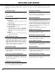
FEATURES AND DESIGN This Multimedia Projector is designed with the most advanced technology for portability, durability, and ease of use. This projector utilizes built-in multimedia features, a palette of 16.77 million colors, and matrix liquid crystal display (LCD) technology. ◆ Compact Design This projector is extremely compact in size and weight. It is designed to be carried and work anywhere you wish to use.
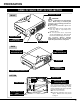
PREPARATION NAME OF EACH PART OF PROJECTOR EXHAUST VENTS FRONT CAUTION Hot air is exhausted from the exhaust vents. When using or installing the projector, the following precautions should be taken. ● Do not put any flammable objects near these vents. ● Keep front grills at least 3’(1m) away from any objects, especially heatsensitive objects. ● Do not touch this area, especially screws and metallic part. This area will become hot while the projector is used.
PREPARATION SETTING-UP PROJECTOR CONNECTING AC POWER CORD This projector uses nominal input voltages of 100-120 V or 200-240 V AC. This projector automatically selects the correct input voltage. It is designed to work with single-phase power systems having a grounded neutral conductor. To reduce risk of electrical shock, do not plug into any other type of power system. Consult your authorized dealer or service station if you are not sure of the type of power being supplied.
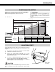
PREPARATION POSITIONING PROJECTOR ● This projector is designed to project on a flat projection surface. ● The projector can be focused from 5.9’(1.8m) ~ 45.9’(14.0m). ● Refer to the figure below to adjust a screen size. ROOM LIGHT The brightness in a room has a great influence on picture quality. It is recommended to limit ambient lighting in order to provide the best image. H1 : H2 = 26 : 1 45.9' (14.0m) 300” 30.5' (9.3m) 23.0' (7.0m) 200” 15.1' (4.6m) Max. Zoom 230” 150” Min. Zoom 153” 5.
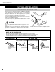
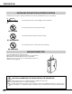
PREPARATION INSTALLING PROJECTOR IN PROPER POSITION Install the projector properly. Improper installation may reduce the lamp lifetime and cause a fire hazard. 20˚ Do not tilt the projector more than 20 degrees above and below. 20˚ Do not point the projector up to project an image. NO UPWARD Do not point the projector down to project an image. NO DOWNWARD Do not put the projector on either side to project an image. NO SIDEWAYS MOVING PROJECTOR Use Carry Handle when moving the projector.
CONNECTING PROJECTOR TERMINALS OF PROJECTOR This projector has input and output terminals on its back for connecting computers and video equipment. Refer to figures on pages 11 to 13 and connect properly. S-VIDEO INPUT JACK AUDIO INPUT JACKS VIDEO INPUT JACKS AUDIO OUTPUT JACKS Connect the S-VIDEO output from video equipment to this jack. (Refer to P13.) Connect the audio output from video equipment to these jacks. (Refer to P13.) ● When the audio output is monaural, connect it to L (MONO) jack.
CONNECTING PROJECTOR CONNECTING TO COMPUTER Cables used for connection (✽ = Cable or adapter is not supplied with this projector.) • VGA Cable (HDB 15 pin) • Control Cable for Serial Port ✽ or ADB Port ✽ • USB Cable ✽ • Control Cable for PS/2 Port • MAC Adapter (When connecting to Macintosh computer) • DVI-VGA Cable (HDB 15 pin) ✽ • DVI-Digital Cable (for Single Link T.M.D.S.
CONNECTING PROJECTOR CONNECTING TO VIDEO EQUIPMENT Cables used for connection • Video Cable (RCA x 1 or RCA x 3) ✽ • S-VIDEO Cable ✽ • Audio Cable (RCA x 2) ✽ (✽ = Cable is not supplied with this projector.) • Scart-VGA Cable ✽ Video Source (example) Component video output equipment.
BEFORE OPERATION OPERATION OF REMOTE CONTROL LASER POINTER (Drag ON) INDICATOR Left Side POWER ON-OFF BUTTON Used to turn the projector on or off. (P19) ON The indicator lights red while the laser beam is emitted from Laser Light Window. It lights green in drag ON position. (P40) AUTO PC ON-OFF D.ZOOM FREEZE NO SHOW ALL OFF LOCK MUTE IMAGE VOLUME- SELECT VOLUME+ MUTE BUTTON Used to mute sound.
BEFORE OPERATION D.ZOOM BUTTON Operating Range Used to select DIGITAL ZOOM +/– mode and resize image. (P30) AUTO PC ON-OFF D.ZOOM FREEZE NO SHOW SELECT BUTTON LOCK Used to execute the item selected, or to expand or compress image in DIGITAL ZOOM +/- mode. (P30) MUTE IMAGE VOLUME- SELECT VOLUME+ KEYSTONE MENU NO SHOW BUTTON Used to turn the picture into black image. (P21) FREEZE BUTTON Point the Remote Control toward projector (Infrared Remote Receiver) whenever pressing any button.
BEFORE OPERATION TOP CONTROLS AND INDICATORS This projector has CONTROL BUTTONS (TOP CONTROLS) and INDICATORS on its top. POWER ON–OFF BUTTON Used to turn the projector on or off. (P19) WARNING TEMP. INDICATOR READY INDICATOR Flashes red when the internal projector temperature is too high. (P41) Lights green when the projector is ready to be turned on. And it flashes green in Power Management mode.
BEFORE OPERATION OPERATING ON-SCREEN MENU HOW TO OPERATE ON-SCREEN MENU You can control and adjust this projector through the ON-SCREEN MENU. Refer to the following pages to operate each adjustment on the ON-SCREEN MENU. AUTO PC ON-OFF Remote Control D.ZOOM FREEZE NO SHOW LOCK 1 DISPLAY MENU Press the MENU button to display the ON-SCREEN MENU.
BEFORE OPERATION MENU BAR FOR PC SOURCE Press the MENU BUTTON while connecting to PC input source. GUIDE WINDOW PC SYSTEM MENU Shows the selected item of the ONSCREEN MENU. Used to select computer system. (Refer to P22- 24) IMAGE SELECT MENU SCREEN MENU SETTING MENU Used to select an image level among Standard, Real and Image 1 ~ 4. (Refer to P28) Used to adjust size of image.
BASIC OPERATION TURNING ON / OFF PROJECTOR TURNING ON PROJECTOR 1 Complete peripheral connections (with Computer, VCR, etc.) before turning on the projector. (Refer to "CONNECTING PROJECTOR" on page 11~13.) 2 Connect the projector's AC Power Cord into an AC outlet. The LAMP Indicator lights red, and the READY Indicator lights green. NOTE : When “On start” function is ON, this projector is turned on automatically by connecting AC Power Cord to an AC outlet. (Refer to the menu item "On start" on page 37.
BASIC OPERATION ADJUSTING SCREEN ZOOM ADJUSTMENT 1 Press the ZOOM button on the Top Control or the ZOOM ▲/▼ button on Remote Control. The message “Zoom” is displayed. 2 Press the ZOOM ▲ button or POINT UP button to make image larger, and press the ZOOM ▼ button or the POINT DOWN button to make image smaller. Zoom The message disappears after 4 seconds. FOCUS ADJUSTMENT 1 Press the FOCUS button on the Top Control or the FOCUS ▲/▼ button on the Remote Control. The message “Focus” is displayed.
BASIC OPERATION NO SHOW FUNCTION Press the NO SHOW button on the Remote Control to black out the image. To restore to normal, press the NO SHOW button again or press any other button. No show The message disappears after 4 seconds. P-TIMER FUNCTION Press the P-TIMER button on the Remote Control. The timer display “00 : 00” appears on the screen and the timer starts to count time (00 : 00 ~ 59 : 59). To stop the P-TIMER display, press the P-TIMER button.
COMPUTER INPUT (RGB Scart 21-Pin Video Input) SELECTING INPUT SOURCE DIRECT OPERATION Choose either Computer 1 or Computer 2 by pressing the INPUT button on the Top Control or press the COMPUTER button on the Remote Control. If the projector cannot reproduce proper image, select correct input source through MENU OPERATION (see below).
COMPUTER INPUT SELECTING COMPUTER SYSTEM This projector automatically tunes to most different types of computers based on VGA, SVGA, XGA, or SXGA (refer to the “COMPATIBLE COMPUTER SPECIFICATIONS” on page 24). When selecting Computer, this projector automatically tunes to incoming signal and projects proper image without any special setting. (Some computers need setting manually.) The projector displays one of the Auto, - - -, Mode 1/2/3/4/5, or the system provided in the projector.
COMPUTER INPUT COMPATIBLE COMPUTER SPECIFICATIONS Basically this projector can accept the signal from all computers with the V, H-Frequency below mentioned and less than 100 MHz of Dot Clock.
COMPUTER INPUT PC ADJUSTMENT AUTO PC ADJUSTMENT Auto PC Adjustment function is provided to automatically adjust Fine sync, Total dots, Horizontal, and Vertical to conform to your computer. Auto PC Adjustment function can be operated as follows. Auto PC Adj. 1 Press the MENU button and the ON-SCREEN MENU will appear. Press the POINT LEFT/RIGHT button to move the red frame pointer to the PC ADJUST Menu icon. 2 Press the POINT DOWN button to move the red frame pointer to the AUTO PC Adj.
COMPUTER INPUT MANUAL PC ADJUSTMENT This projector can automatically tune to the display signals from most personal computers currently distributed. However, some computers employ special signal formats which are different from the standard ones and may not be tuned by MultiScan system of this projector. If this happens, the projector cannot reproduce a proper image and the image may be recognized as a flickering picture, a non-synchronized picture, a non-centered picture or a skewed picture.
COMPUTER INPUT Display area Selects the area displayed by this projector. Select the resolution at the Display area dialog box. Press the SELECT button at the Display area icon and the Display area dialog box appears. Display area H Adjustment of the horizontal area displayed by this projector. Press the POINT LEFT/RIGHT button(s) to decrease/increase value and then press the SELECT button. Display area Display area V Adjustment of the vertical area displayed by this projector.
COMPUTER INPUT PICTURE IMAGE ADJUSTMENTS IMAGE LEVEL SELECT (DIRECT) Select an image level among Standard, Real, Image 1, Image 2, Image 3, and Image 4 by pressing the IMAGE button on the Top Control or on the Remote Control. IMAGE button Standard Real Standard Normal picture level preset on this projector. Image 1 Real Picture level with improved halftone for graphics. Image 2 IMAGE 1~4 User preset picture adjustment in the IMAGE ADJUST Menu (P29, 30).
COMPUTER INPUT IMAGE LEVEL ADJUSTMENT 1 Press the MENU button and the ON-SCREEN MENU will appear. Press the POINT LEFT/RIGHT buttons to move the red frame pointer to the IMAGE ADJUST Menu icon. 2 Press the POINT DOWN button to move the red frame pointer to the item that you want to adjust, and then press the SELECT button. The level of each item is displayed. Adjust each level by pressing the POINT LEFT/RIGHT button(s).
COMPUTER INPUT 3 Store To store manually preset image, move the red frame pointer to the Store icon and press the SELECT button. The Image Level Menu will appear. Move the red frame pointer to the Image 1 to 4 where you want to set and then press the SELECT button. Other icons operate as follows. Reset Reset all adjustment to their previous levels. Quit Closes the IMAGE MENU.
VIDEO INPUT SELECTING INPUT SOURCE DIRECT OPERATION Choose Video by pressing the INPUT button on the Top Control or on the Remote Control. If the projector cannot reproduce proper video source, select correct input source through MENU OPERATION (see below). INPUT button Video Computer 1 RGB Scart Input To select RGB Scart 21-Pin video input through the COMPUTER IN 2 / MONITOR OUT terminal, see "COMPUTER INPUT (RGB Scart 21Pin Video Input)" on page 22.
VIDEO INPUT SELECTING VIDEO SYSTEM 1 Press the MENU button and the ON-SCREEN MENU will appear. Press the POINT LEFT/RIGHT buttons to move the red frame pointer to the AV SYSTEM Menu icon. 2 Press the POINT DOWN button to move the red arrow pointer to the system that you want to select and then press the SELECT button. VIDEO JACK OR S-VIDEO JACK AV SYSTEM MENU (VIDEO OR S-VIDEO) Auto The projector automatically detects incoming Video system, and adjusts itself to optimize its performance.
VIDEO INPUT PICTURE IMAGE ADJUSTMENTS IMAGE LEVEL SELECT (DIRECT) Select an image level among Standard, Cinema, Image 1, Image 2, Image 3, and Image 4 by pressing the IMAGE button on the Top Control or on the Remote Control. IMAGE button Standard Cinema Standard Normal picture level preset on this projector. Image 1 Cinema Picture level adjusted for the picture with fine tone. Image 2 IMAGE 1~4 User preset picture adjustment in the IMAGE ADJUST Menu (P34, 35).
VIDEO INPUT IMAGE LEVEL ADJUSTMENT 1 Press the MENU button and the ON-SCREEN MENU will appear. Press the POINT LEFT/RIGHT button(s) to move the red frame pointer to the IMAGE ADJUST Menu icon. 2 Press the POINT DOWN button to move the red frame pointer to the item that you want to adjust and then press the SELECT button. The level of each item is displayed. Adjust each level by pressing the POINT LEFT/RIGHT button(s).
VIDEO INPUT 3 Store To store the adjustment data, move the red frame pointer to the Store icon and press the SELECT button. The Image Level Menu will appear. Move the red frame pointer to the Image Level 1 to 4 and then press the SELECT button. Image Level Menu Move the red frame pointer to the image icon to be set and then press the SELECT button. Other icons operate as follows. Reset Reset all adjustment to their previous figure. Quit Closes the IMAGE MENU.
SETTING SETTING MENU 1 Press the MENU button and the ON-SCREEN MENU will appear. Press the POINT LEFT/RIGHT button(s) to move the red frame pointer to the SETTING Menu icon. 2 Press the POINT DOWN button to move the red frame pointer to the item that you want to set and then press the SELECT button. The Setting dialog box appears. SETTING MENU Set the red frame pointer to the item and press the SELECT button.
SETTING Power management This function turns the Projection Lamp off when this projector detects signal interruption and is not used for a certain period in order to reduce power consumption and maintain the Lamp-life. (This projector is shipped with this function ON.) The Power Management function operates to turn the Projection Lamp off when the input signal is interrupted and any button is not pressed over 5 minutes. This function operates as follows; 1.
APPENDIX LAMP REPLACEMENT ON -- OFF LAMP REPLACE When the life of the Projection Lamp of this projector draws to an end, the LAMP REPLACE indicator lights yellow. If this indicator lights yellow, replace the projection lamp with a new one promptly. TOP CONTROL WARNING TEMP. This indicator lights yellow when the life of the projection lamp draws to an end. Replace the Projection Lamp with a new one promptly.
APPENDIX LAMP REPLACE COUNTER Be sure to reset the Lamp Replace Counter after the Lamp Assembly is replaced. When the Lamp Replace Counter is reset, the LAMP REPLACE Indicator stops lighting. 1 Turn the projector on, press the MENU button and the ONSCREEN MENU will appear. Press the POINT LEFT/RIGHT button(s) to move the red frame pointer to the SETTING Menu icon (refer to page 36, 37). 2 Press the POINT DOWN button to move the red frame pointer to “Lamp counter reset” and then press the SELECT button.
APPENDIX OPERATING WIRELESS MOUSE The Remote Control is not only able to operate this projector but also usable as a wireless mouse for most Personal Computers. The POINT button, drag ON/OFF button and two CLICK buttons are used for wireless mouse operation. This Wireless Mouse function is available only when PC mouse pointer is displayed on a projected screen. INSTALLATION To use the Remote Control as Wireless Mouse for a Personal Computer, installation of the mouse driver (not supplied) is required.
APPENDIX MAINTENANCE WARNING TEMP. INDICATOR The WARNING TEMP. indicator flashes red when an internal temperature of the projector exceeds the normal temperature. The projector cannot be turned on while the WARNING TEMP. indicator is flashing with the READY indicator off. When the temperature inside the projector returns to normal, the READY indicator lights green. Then youONcan -- OFF turn the projector back on. The WARNING TEMP indicator stops flashing after turning the projector on.
APPENDIX TROUBLESHOOTING Before calling your dealer or service center for assistance, check the items below once again. ● Make sure you have connected the projector to peripheral equipment as described properly in the section "CONNECTING PROJECTOR" on pages 11 ~ 13. ● Verify that all computer, video and power cord are properly connected and turn the equipment on. ● When you are operating the projector with a computer and it does not produce an image, restart the computer. ● Select the other input source.
APPENDIX Problem: Try these Solutions Remote Control does not work. ● ● ● ● Wireless Mouse function does not work. ● Check cable connection between the projector and your computer. ● Check the mouse setting on your computer. ● Turn the projector on before turning on the computer. Check the batteries. Check ALL-OFF switch on the Remote Control is set to “ON.” Make sure there is no obstructions between the projector and the Remote Control.
APPENDIX INDICATORS AND PROJECTOR CONDITION Check the Indicators for projector condition. Indicators LAMP REPLACE yellow WARNING TEMP. red READY LAMP green red Projector Condition The projector is OFF. (The AC Power Cord is unplugged.) ✽ The projector is READY to be turned on with the POWER ON-OFF button. ✽ The projector is operating normally. ✽ The temperature inside the projector is abnormally high. The projector cannot be turned on.
APPENDIX TECHNICAL SPECIFICATIONS Projector Type Dimensions (W x H x D) Net Weight LCD Panel System Panel Resolution Number of Pixels Color System High Definition TV Signal Scanning Frequency Projection Image size (Diagonal) Projection Lens Throw Distance Projection Lamp Video Input Jacks Audio Input Jacks Computer Input Terminal Computer Input / Monitor Output Terminal Computer Audio Input Jack Control Port Connector USB Connector Audio Output Jacks Internal Audio Amp Built-in Speaker Feet Adjustment Volt
APPENDIX CONFIGURATIONS OF TERMINALS COMPUTER INPUT/MONITOR OUTPUT TERMINAL (ANALOG) Terminal : HDB15-PIN Pin Configuration 4 5 10 15 14 2 3 9 8 13 1 7 12 1 2 3 4 5 6 7 8 6 11 Red Input Green Input Blue Input Sense 2 Ground (Horiz.sync.) Ground (Red) Ground (Green) Ground (Blue) 9 10 11 12 13 14 15 +5V Power Ground (Vert.sync.) Sense 0 DDC Data Horiz. sync. Vert. sync.
APPENDIX CONTROL PORT CONNECTOR Terminal : Mini DIN 8-PIN Pin Configuration 8 5 7 6 4 3 2 1 1 2 3 4 5 6 7 8 PS/2 ----CLK DATA GND --------GND ----- 1 2 3 4 Vcc - Data + Data Ground Serial RXD --------GND RTS / CTS TXD GND GND ADB ----ADB ----GND ------------GND USB CONNECTOR (Series B) Pin Configuration 2 1 3 4 OPTIONAL PARTS The parts listed below are optionally supplied. When ordering those parts, give the name and Type No. to the sales dealer. ● Control Cable (Serial Port) Type No.
Printed in Japan Part No. 610 306 6097 (1AA6P1P3996-- MK7A) SANYO Electric Co., Ltd.