Multimedia Projector MODEL PLC-XR201 PLC-XR251 Owner’s Manual Network Supported Ƒ :LUHG /$1 %DVH 7; %DVH 7 5HIHU WR WKH 2ZQHU V 0DQXDOV EHORZ IRU GHWDLOV DERXW QHWZRUN IXQFWLRQ Ƒ 1HWZRUN 6HW XS DQG 2SHUDWLRQ Ƒ 3- 1HWZRUN 0DQDJHU
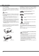
Features and Design 7KLV 0XOWLPHGLD 3URMHFWRU LV GHVLJQHG ZLWK WKH PRVW DGYDQFHG WHFKQRORJ\ IRU SRUWDELOLW\ GXUDELOLW\ DQG HDVH RI XVH 7KLV SURMHFWRU XWLOL]HV EXLOW LQ PXOWLPHGLD IHDWXUHV D SDOHWWH RI PLOOLRQ FRORUV DQG PDWUL[ OLTXLG FU\VWDO GLVSOD\ /&' WHFKQRORJ\ Ƈ Ƈ Compact Design 7KLV SURMHFWRU LV GHVLJQHG FRPSDFW LQ VL]H DQG ZHLJKW ,W LV HDV\ WR FDUU\ DQG LQVWDOOHG DQ\ZKHUH \RX ZLVK WR XVH Ƈ Simple Computer System Setting 7KH SURMHFWRU KDV WKH 0XOWL VFDQ V\VWH
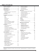
Table of Contents Features and Design . . . . . . . . . . . . . . . . . . .2 Table of Contents . . . . . . . . . . . . . . . . . . . . . .3 To the Owner. . . . . . . . . . . . . . . . . . . . . . . . . .4 Safety Instructions . . . . . . . . . . . . . . . . . . . . .5 $LU &LUFXODWLRQ ,QVWDOOLQJ WKH 3URMHFWRU LQ 3URSHU 3RVLWLRQ 0RYLQJ WKH 3URMHFWRU Compliance . . . . . . . . . . . . . . . . . . . . . . . . . . .7 Part Names and Functions . . . . . . . . . . . . . .
To the Owner %HIRUH LQVWDOOLQJ DQG RSHUDWLQJ WKLV SURMHFWRU UHDG WKLV PDQXDO WKRURXJKO\ 7KLV SURMHFWRU SURYLGHV PDQ\ FRQYHQLHQW IHDWXUHV DQG IXQFWLRQV 2SHUDWLQJ WKH SURMHFWRU SURSHUO\ HQDEOHV \RX WR PDQDJH WKRVH IHDWXUHV DQG PDLQWDLQV LW LQ JRRG FRQGLWLRQ IRU PDQ\ \HDUV WR FRPH ,PSURSHU RSHUDWLRQ PD\ UHVXOW LQ QRW RQO\ VKRUWHQLQJ WKH SURGXFW OLIH EXW DOVR PDOIXQFWLRQV ILUH KD]DUG RU RWKHU DFFLGHQWV ,I \RXU SURMHFWRU VHHPV WR RSHUDWH LPSURSHUO\ UHDG WKLV PDQXDO DJDLQ FKHFN RSHUDWLRQV DQG FDE
Safety Instructions $OO WKH VDIHW\ DQG RSHUDWLQJ LQVWUXFWLRQV VKRXOG EH UHDG EHIRUH WKH SURGXFW LV RSHUDWHG 'R QRW LQVWDOO WKH SURMHFWRU QHDU WKH YHQWLODWLRQ GXFW RI DLU FRQGLWLRQLQJ HTXLSPHQW 5HDG DOO RI WKH LQVWUXFWLRQV JLYHQ KHUH DQG UHWDLQ WKHP IRU ODWHU XVH 8QSOXJ WKLV SURMHFWRU IURP $& SRZHU VXSSO\ EHIRUH FOHDQLQJ 'R QRW XVH OLTXLG RU DHURVRO FOHDQHUV 8VH D GDPS FORWK IRU FOHDQLQJ 7KLV SURMHFWRU VKRXOG EH RSHUDWHG RQO\ IURP WKH W\SH RI SRZHU V
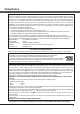
Safety Instructions Air Circulation Installing the Projector in Proper Position 2SHQLQJV LQ WKH FDELQHW DUH SURYLGHG IRU YHQWLODWLRQ 7R HQVXUH UHOLDEOH RSHUDWLRQ RI WKH SURGXFW DQG WR SURWHFW LW IURP RYHUKHDWLQJ WKHVH RSHQLQJV PXVW QRW EH EORFNHG RU FRYHUHG ,QVWDOO WKH SURMHFWRU SURSHUO\ ,PSURSHU ,QVWDOODWLRQ PD\ UHGXFH WKH ODPS OLIH DQG FDXVH D ILUH KD]DUG CAUTION +RW DLU LV H[KDXVWHG IURP WKH H[KDXVW YHQW :KHQ XVLQJ RU LQVWDOOLQJ WKH SURMHFWRU WKH IROORZLQJ SUH
Compliance Federal Communications Commission Notice 1RWH 7KLV HTXLSPHQW KDV EHHQ WHVWHG DQG IRXQG WR FRPSO\ ZLWK WKH OLPLWV IRU D &ODVV % GLJLWDO GHYLFH SXUVXDQW WR 3DUW RI WKH )&& 5XOHV 7KHVH OLPLWV DUH GHVLJQHG WR SURYLGH UHDVRQDEOH SURWHFWLRQ DJDLQVW KDUPIXO LQWHUIHUHQFH LQ D UHVLGHQWLDO LQVWDOODWLRQ 7KLV HTXLSPHQW JHQHUDWHV XVHV DQG FDQ UDGLDWH UDGLR IUHTXHQF\ HQHUJ\ DQG LI QRW LQVWDOOHG DQG XVHG LQ DFFRUGDQFH ZLWK WKH LQVWUXFWLRQV PD\ FDXVH KDUPI
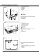
Part Names and Functions ① Top controls and Indicators ② Zoom Ring Front ② ① ③ Focus Ring ④ Speaker ③ ⑤ Infrared Remote Receiver ⑥ Projection Lens ⑦ Lens Cap 6HH SDJH IRU DWWDFKLQJ CAUTION 'R QRW WXUQ RQ D SURMHFWRU ZLWK OHQV FDS DWWDFKHG +LJK WHPSHUDWXUH IURP OLJKW EHDP PD\ GDPDJH OHQV FDS DQG UHVXOW LQ ILUH KD]DUG ⑧ Air Intake Vent ④ ⑤ ⑥ ⑦ ⑧ ⑨ Lamp Cover Back ⑨ ⑩ ⑪ ⑩ Terminals and Connectors ⑪ LAN Connection Terminal ⑫ Power Cord Connector ⑬ Exhaust Vents CAUTION +RW DLU LV H[K
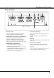
Part Names and Functions Rear Terminal ① ② ③ ④ ⑤ ⑥ ⑦ ① CONTROL PORT :KHQ WKH SURMHFWRU LV FRQWUROOHG E\ D FRPSXWHU FRQQHFW WR WKLV MDFN ZLWK VHULDO FRQWURO FDEOH ② COMPUTER IN 1 /S-VIDEO IN / COMPONENT IN &RQQHFW DQDORJ 5*% RXWSXW VLJQDO IURP D FRPSXWHU 6 9,'(2 RXWSXW VLJQDO IURP YLGHR HTXLSPHQW RU 5*% VFDUW SLQ YLGHR RXWSXW RU FRPSRQHQW YLGHR RXWSXW WR WKLV WHUPLQDO SS ③ COMPUTER IN 2 / MONITOR OUT ± &RQQHFW DQDORJ 5*% RXWSXW VLJQDO IURP D FRPSXWHU WR WKLV WHUPLQD
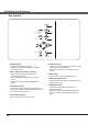
Part Names and Functions Top Control ⑤ ⑧ ④ ⑦ ③ ② ⑥ ① SELECT button ± ([HFXWH WKH VHOHFWHG LWHP S ± ([SDQG RU FRPSUHVV WKH LPDJH LQ WKH 'LJLWDO ]RRP PRGH S ② POINT ŸźŻŹ (VOLUME +/–) buttons ± 6HOHFW DQ LWHP RU DGMXVW WKH YDOXH LQ WKH 2Q 6FUHHQ 0HQX S ± 3DQ WKH LPDJH LQ WKH 'LJLWDO ]RRP PRGH S ± $GMXVW WKH YROXPH OHYHO 3RLQW ŻŹEXWWRQV S ③ AUTO SETUP button ([HFXWH WKH VHWWLQJ RI $XWR VHWXS LQFOXGHV ,QSXW VHDUFK $XWR 3& DGM DQG $XWR .
Part Names and Functions Remote Control ① ON/STAND-BY button 7XUQ WKH SURMHFWRU RQ RU RII SS ② AUTO SET button ([HFXWH WKH VHWWLQJ RI $XWR VHWXS LQFOXGHV ,QSXW VHDUFK $XWR 3& DGM DQG $XWR .
Part Names and Functions Remote Control Battery Installation 1 2SHQ WKH EDWWHU\ FRPSDUWPHQW OLG 2 ,QVWDOO QHZ EDWWHULHV LQWR WKH FRPSDUWPHQW 3 5HSODFH WKH FRPSDUWPHQW OLG Two AAA size batteries )RU FRUUHFW SRODULW\ DQG ± EH VXUH EDWWHU\ WHUPLQDOV DUH LQ FRQWDFW ZLWK SLQV LQ FRPSDUWPHQW 7R HQVXUH VDIH RSHUDWLRQ SOHDVH REVHUYH WKH IROORZLQJ SUHFDXWLRQV Ɣ 8VH WZR $$$ RU /5 W\SH DONDOLQH EDWWHULHV Ɣ $OZD\V UHSODFH EDWWHULHV LQ VHWV Ɣ 'R QRW XVH D QHZ EDWWHU\ ZLWK D XVH
Installation Positioning the Projector )RU SURMHFWRU SRVLWLRQLQJ VHH WKH ILJXUHV EHORZ 7KH SURMHFWRU VKRXOG EH VHW SHUSHQGLFXODUO\ WR WKH SODQH RI WKH VFUHHQ 3Note: 7KH EULJKWQHVV LQ WKH URRP KDV D JUHDW LQIOXHQFH RQ SLFWXUH TXDOLW\ ,W LV UHFRPPHQGHG WR OLPLW DPELHQW OLJKWLQJ LQ RUGHU WR REWDLQ WKH EHVW LPDJH $OO PHDVXUHPHQWV DUH DSSUR[LPDWH DQG PD\ YDU\ IURP WKH DFWXDO VL]HV 38.7'(11.80m) A:B = 6:1 (Inch Diagonal) 32.3'(9.84m) 300"(tele ) 300"(wide) 21.5'(6.55m) Max.
Installation Connecting to a Computer Cables used for connection 9*$ &DEOHV 0LQL ' VXE SLQ 2QO\ RQH FDEOH LV VXSSOLHG $XGLR &DEOHV ( 2QH FDEOH LV VXSSOLHG RWKHU FDEOHV DUH QRW VXSSOLHG ZLWK WKH SURMHFWRU $XGLR 2XWSXW 0RQLWRU 2XWSXW 0RQLWRU ,QSXW RU 0RQLWRU 2XWSXW ([WHUQDO $XGLR (TXLSPHQW 9*$ FDEOH 9*$ FDEOH $XGLR FDEOH VWHUHR $XGLR ,QSXW &20387(5 ,1 6 9,'(2 ,1 &20321(17 ,1 &20387(5 ,1 021,725 287 7KLV WHUPLQDO LV VZLWFKDEOH 6HW XS WKH WHUPLQDO DV HLWKH
Installation Connecting to Video Equipment Cables used for connection 9LGHR &DEOH 6 9LGHR &DEOH 6 9LGHR 9*$ &DEOH $XGLR &DEOHV 0LQL 3OXJ VWHUHR &DEOHV DUH QRW VXSSOLHG ZLWK WKH SURMHFWRU ([WHUQDO $XGLR (TXLSPHQW 6 9LGHR 2XWSXW $XGLR 2XWSXW $XGLR ,QSXW &RPSRVLWH 9LGHR DQG $XGLR 2XWSXW 6 9LGHR FDEOH $XGLR FDEOH $XGLR FDEOH VWHUHR VWHUHR 9LGHR FDEOH 6 9LGHR 9*$ FDEOH &20387(5 ,1 6 9,'(2 ,1 &20321(17 ,1 $8',2 ,1 $8',2 287 VWHUHR 9,'(2 ,1 3Note: :KHQ WKH $8',2 287
Installation Connecting to Component Video and RGB ( Scart) Equipment Cables used for connection $XGLR &DEOHV 0LQL 3OXJ VWHUHR 6FDUW 9*$ &DEOH &RPSRQHQW &DEOH &RPSRQHQW 9*$ &DEOH &DEOHV DUH QRW VXSSOLHG ZLWK WKLV SURMHFWRU $XGLR 2XWSXW &RPSRQHQW 9LGHR 2XWSXW < 3E &E 3U &U 5*% 6FDUW SLQ 2XWSXW &RPSRQHQW FDEOH $XGLR ,QSXW ([WHUQDO $XGLR (TXLSPHQW 6FDUW 9*$ FDEOH &RPSRQHQW 9*$ FDEOH $XGLR FDEOH VWHUHR &20387(5 ,1 6 9,'(2 ,1 &20321(17 ,1 $XGLR FDEOH VWHUHR $8',2
Installation Connecting the AC Power Cord 7KLV SURMHFWRU XVHV QRPLQDO LQSXW YROWDJHV RI 9 RU ± 9 $& DQG LW DXWRPDWLFDOO\ VHOHFWV WKH FRUUHFW LQSXW YROWDJH ,W LV GHVLJQHG WR ZRUN ZLWK VLQJOH SKDVH SRZHU V\VWHPV KDYLQJ D JURXQGHG QHXWUDO FRQGXFWRU 7R UHGXFH WKH ULVN RI HOHFWULFDO VKRFN GR QRW SOXJ LQWR DQ\ RWKHU W\SH RI SRZHU V\VWHP ,I \RX DUH QRW VXUH RI WKH W\SH RI SRZHU EHLQJ VXSSOLHG FRQVXOW \RXU DXWKRUL]HG GHDOHU RU VHUYLFH VWDWLRQ &RQQHFW WKH
Basic Operation Turning On the Projector 1 &RPSOHWH SHULSKHUDO FRQQHFWLRQV ZLWK D FRPSXWHU 9&5 HWF EHIRUH WXUQLQJ RQ WKH SURMHFWRU 2 &RQQHFW WKH SURMHFWRU¶V $& SRZHU FRUG LQWR DQ $& RXWOHW 7KH 32:(5 LQGLFDWRU OLJKWV UHG 2SHQ WKH OHQV FDS VHH SDJHV 3 3UHVV WKH 21 6<$1' %< EXWWRQ RQ WKH WRS FRQWURO RU RQ WKH UHPRWH FRQWURO 7KH 32:(5 LQGLFDWRU OLJKWV JUHHQ DQG WKH FRROLQJ IDQV VWDUW WR RSHUDWH 7KH SUHSDUDWLRQ GLVSOD\ DSSHDUV RQ WKH VFUHHQ DQG WKH FRXQWGRZQ VWDUWV 4 5 $IWHU
Basic Operation Enter a PIN code 8VH WKH 3RLQW Ÿź EXWWRQV WR HQWHU D QXPEHU 3UHVV WKH 3RLQW Ż Ź EXWWRQV WR IL[ WKH QXPEHU DQG PRYH WKH UHG IUDPH SRLQWHU WR WKH QH[W ER[ 7KH QXPEHU FKDQJHV WR ³¼´ ,I \RX IL[HG DQ LQFRUUHFW QXPEHU XVH WKH 3RLQW Ż Ź EXWWRQV WR PRYH WKH SRLQWHU WR WKH QXPEHU \RX ZDQW WR FRUUHFW DQG WKHQ HQWHU WKH FRUUHFW QXPEHU 5HSHDW WKLV VWHS WR FRPSOHWH HQWHULQJ D IRXU GLJLW QXPEHU $IWHU HQWHULQJ WKH IRXU GLJLW QXPEHU PRYH WKH SRLQWHU WR Set 3UHVV WKH 6(/(&7 EXWWRQ VR WKDW \RX
Basic Operation Turning Off the Projector 1 3UHVV WKH 21 67$1' %< EXWWRQ RQ WKH WRS FRQWURO RU RQ WKH UHPRWH FRQWURO DQG Power off? DSSHDUV RQ WKH VFUHHQ 2 3UHVV WKH 21 67$1' %< EXWWRQ DJDLQ WR WXUQ RII WKH SURMHFWRU 7KH 32:(5 LQGLFDWRU VWDUWV WR EOLQN UHG DQG WKH FRROLQJ IDQV NHHS UXQQLQJ
Basic Operation How to Operate the On-Screen Menu 7KH SURMHFWRU FDQ EH DGMXVWHG RU VHW YLD WKH 2Q 6FUHHQ 0HQX 7KH PHQXV KDYH D KLHUDUFKLFDO VWUXFWXUH ZLWK D PDLQ PHQX WKDW LV GLYLGHG LQWR VXEPHQXV ZKLFK DUH IXUWKHU GLYLGHG LQWR RWKHU VXEPHQXV )RU HDFK DGMXVWPHQW DQG VHWWLQJ SURFHGXUH UHIHU WR UHVSHFWLYH VHFWLRQV LQ WKLV PDQXDO 1 Top Control POINT buttons (arrowhead) 3UHVV WKH 0(18 EXWWRQ RQ WKH WRS FRQWURO RU WKH UHPRWH FRQWURO WR GLVSOD\ WKH 2Q 6FUHHQ 0HQX SELECT button 2 8VH WKH 3RLQW
Basic Operation Menu Bar )RU GHWDLOHG IXQFWLRQV RI HDFK PHQX VHH ³0HQX 7UHH´ RQ SDJHV 0DLQ 0HQX 6XE 0HQX ① ② ③ ④ ⑤ ⑥ ⑦ ⑧ ⑨ ⑩ ① Input 8VHG WR VHOHFW DQ LQSXW VRXUFH IURP Computer 1 Computer 2 RU Video SS ② PC adjust 6HOHFW Auto PC adj.
Basic Operation Zoom and Focus Adjustment 5RWDWH WKH =RRP 5LQJ WR ]RRP LQ DQG RXW 5RWDWH WKH )RFXV 5LQJ WR DGMXVW WKH IRFXV RI WKH LPDJH =RRP 5LQJ Auto Setup Function $XWR VHWXS IXQFWLRQ LV SURYLGHG WR DXWRPDWLFDOO\ H[HFXWH WKH VHWWLQJ RI $XWR VHWXS LQFOXGHV ,QSXW VHDUFK $XWR 3& DGM DQG $XWR .
Basic Operation Sound Adjustment Direct Operation Top Control VOLUME+/buttons Volume 3UHVV WKH 92/80( ± EXWWRQV RQ WKH WRS FRQWURO RU RQ WKH UHPRWH FRQWURO WR DGMXVW WKH YROXPH 7KH YROXPH GLDORJ ER[ DSSHDUV RQ WKH VFUHHQ IRU D IHZ VHFRQGV Mute Remote Control 3UHVV WKH 087( EXWWRQ RQ WKH UHPRWH FRQWURO WR VHOHFW On WR WHPSRUDULO\ WXUQ RII WKH VRXQG 7R WXUQ WKH VRXQG EDFN RQ SUHVV WKH 087( EXWWRQ DJDLQ WR VHOHFW Off RU SUHVV WKH 92/80( ± EXWWRQV 7KH 0XWH IXQFWLRQ LV DOVR HIIHFWLYH
Basic Operation Remote Control Operation 8VLQJ WKH UHPRWH FRQWURO IRU VRPH IUHTXHQWO\ XVHG RSHUDWLRQV LV DGYLVDEOH -XVW SUHVVLQJ RQH RI WKH EXWWRQV HQDEOHV \RX WR PDNH WKH GHVLUHG RSHUDWLRQ TXLFNO\ ZLWKRXW FDOOLQJ XS WKH 2Q 6FUHHQ 0HQX COMPUTER 1/2, VIDEO, S-VIDEO and COMPONENT buttons 3UHVV WKH &20387(5 9,'(2 6 9,'(2 DQG &20321(17 EXWWRQV RQ WKH UHPRWH FRQWURO WR VHOHFW WKH LQSXW VRXUFH 6HH SDJHV IRU GHWDLOV FREEZE button 3UHVV WKH )5((=( EXWWRQ RQ WKH UHPRWH FRQWURO WR IUHH]H WKH
Basic Operation NO SHOW button 3UHVV WKH 12 6+2: EXWWRQ RQ WKH UHPRWH FRQWURO WR EODFN RXW WKH LPDJH 7R UHVWRUH WR QRUPDO SUHVV WKH 12 6+2: EXWWRQ DJDLQ RU SUHVV DQ\ RWKHU EXWWRQ 7KH VFUHHQ FKDQJHV HDFK WLPH \RX SUHVV WKH 12 6+2: EXWWRQ DV IROORZV EODFN RXW ĺ QRUPDO ĺ EODFN RXW ĺ QRUPDO No show GLVDSSHDUV DIWHU VHFRQGV P-TIMER button 3UHVV WKH 3 7,0(5 EXWWRQ RQ WKH UHPRWH FRQWURO 7KH 3 7LPHU GLVSOD\ 00:00 DSSHDUV RQ WKH VFUHHQ DQG WKH FRXQWGRZQ VWDUWV ± 7R V
Computer Input Input Source Selection (RGB: Computer 1/Computer 2) Direct Operation &KRRVH HLWKHU Computer 1(RGB) RU Computer 2(RGB) E\ SUHVVLQJ WKH &20387(5 RU &RPSXWHU EXWWRQ RQ WKH UHPRWH FRQWURO %HIRUH XVLQJ WKHVH EXWWRQV FRUUHFW LQSXW VRXUFH VKRXOG EH VHOHFWHG WKURXJK 0HQX RSHUDWLRQ DV GHVFULEHG EHORZ Remote Control COMPUTER 1 button Computer 1(RGB) Computer 1(Scart) COMPUTER 2 button Computer 2 (RGB) Input Menu Menu Operation 1 3UHVV WKH 0(18 EXWWRQ WR GLVSOD\ WKH 2Q 6FUHHQ
Computer Input Computer System Selection 7KLV SURMHFWRU DXWRPDWLFDOO\ WXQHV WR YDULRXV W\SHV RI FRPSXWHUV EDVHG RQ 9*$ 69*$ ;*$ 6;*$ :;*$ RU :8;*$ ZLWK LWV 0XOWL VFDQ V\VWHP DQG $XWR 3& $GMXVWPHQW ,I D FRPSXWHU LV VHOHFWHG DV D VLJQDO VRXUFH WKLV SURMHFWRU DXWRPDWLFDOO\ GHWHFWV WKH VLJQDO IRUPDW DQG WXQHV WR SURMHFW D SURSHU LPDJH ZLWKRXW DQ\ DGGLWLRQDO VHWWLQJV 6LJQDO IRUPDWV SURYLGHG LQ WKLV SURMHFWRU DUH VKRZQ RQ SDJH 2QH RI WKH IROORZLQJ PHVVDJHV PD\ DSSHDU ZKHQ Auto 7KH SURMHFWRU FDQQR
Computer Input Auto PC Adjustment $XWR 3& $GMXVWPHQW IXQFWLRQ LV SURYLGHG WR DXWRPDWLFDOO\ DGMXVW Fine sync Total dots Horizontal DQG Vertical SRVLWLRQV WR FRQIRUP WR \RXU FRPSXWHU Menu Operation PC adjust Menu Auto PC adj. 1 3UHVV WKH 0(18 EXWWRQ WR GLVSOD\ WKH 2Q 6FUHHQ 0HQX 8VH WKH 3RLQW Ÿź EXWWRQV WR VHOHFW PC adjust DQG WKHQ SUHVV WKH 3RLQW Ź RU WKH 6(/(&7 EXWWRQ 2 8VH WKH 3RLQW Ÿź EXWWRQV WR VHOHFW Auto PC adj.
Computer Input Manual PC Adjustment 6RPH FRPSXWHUV HPSOR\ VSHFLDO VLJQDO IRUPDWV ZKLFK PD\ QRW EH WXQHG E\ 0XOWL VFDQ V\VWHP RI WKLV SURMHFWRU 0DQXDO 3& $GMXVWPHQW HQDEOHV \RX WR SUHFLVHO\ DGMXVW VHYHUDO SDUDPHWHUV WR PDWFK WKRVH VLJQDO IRUPDWV 7KH SURMHFWRU KDV ILYH LQGHSHQGHQW PHPRU\ DUHDV WR VWRUH WKRVH SDUDPHWHUV PDQXDOO\ DGMXVWHG ,W DOORZV \RX WR UHFDOO WKH VHWWLQJ IRU D VSHFLILF FRPSXWHU 1 3UHVV WKH 0(18 EXWWRQ WR GLVSOD\ WKH 2Q 6FUHHQ 0HQX 8VH WKH 3RLQW Ÿź EXWWRQV WR VHOHF
Computer Input Reset 7R UHVHW WKH DGMXVWHG GDWD VHOHFW Reset DQG SUHVV WKH 6(/(&7 EXWWRQ $ FRQILUPDWLRQ ER[ DSSHDUV DQG WKHQ VHOHFW Yes $OO DGMXVWPHQWV ZLOO UHWXUQ WR WKHLU SUHYLRXV ILJXUHV Mode free Mode free 7R FOHDU WKH VWRUHG GDWD VHOHFW Mode free DQG WKHQ SUHVV WKH 3RLQW Ź RU WKH 6(/(&7 EXWWRQ 0RYH WKH KLJKOLJKW WR WKH 0RGH WKDW \RX ZDQW WR FOHDU DQG WKHQ SUHVV WKH 6(/(&7 EXWWRQ 7KLV 0RGH KDV VWRUHG SDUDPHWHUV Store 7R VWRUH WKH DGMXVWHG GDWD VHOHFW Store DQG WKHQ SUHVV WK
Computer Input Image Mode Selection Direct Operation Remote Control 6HOHFW WKH GHVLUHG LPDJH PRGH DPRQJ Dynamic Standard Real Blackboard (Green) Colorboard Image 1 Image 2 Image 3 DQG Image 4 E\ SUHVVLQJ WKH ,0$*( EXWWRQ RQ WKH UHPRWH FRQWURO IMAGE button Dynamic Standard Real Blackboard(Green) IMAGE button Colorboard Image 1 Image 2 Menu Operation 1 2 Image 4 8VH WKH 3RLQW Ÿź EXWWRQV WR VHOHFW WKH GHVLUHG LWHP DQG WKHQ SUHVV WKH 6(/(&7 EXWWRQ Dynamic )RU YLHZLQJ SLFWXUHV LQ D EULJKW
Computer Input Image Adjustment 1 3UHVV WKH 0(18 EXWWRQ WR GLVSOD\ WKH 2Q 6FUHHQ 0HQX 8VH WKH 3RLQW Ÿź EXWWRQV WR VHOHFW Image adjust DQG WKHQ SUHVV WKH 3RLQW ŹRU WKH 6(/(&7 EXWWRQ 2 8VH WKH 3RLQW Ÿź EXWWRQV VHOHFW WKH GHVLUHG LWHP DQG WKHQ SUHVV WKH 6(/(&7 EXWWRQ WR GLVSOD\ WKH DGMXVWPHQW GLDORJ ER[ 8VH WKH 3RLQW ŻŹ EXWWRQV WR DGMXVW WKH VHWWLQJ YDOXH Image Adjust Menu Contrast 3UHVV WKH 3RLQW Ż EXWWRQ WR GHFUHDVH WKH FRQWUDVW SUHVV WKH 3RLQW ŹEXWWRQ WR LQFUHDVH WKH FRQWUDVW IURP WR
Computer Input Store 7R VWRUH WKH DGMXVWHG GDWD VHOHFW Store DQG SUHVV WKH 3RLQW ŹRU WKH 6(/(&7 EXWWRQ 8VH WKH 3RLQW Ÿź EXWWRQV WR VHOHFW RQH IURP Image 1 WR 4 DQG SUHVV WKH 6(/(&7 EXWWRQ $ FRQILUPDWLRQ ER[ DSSHDUV DQG WKHQ VHOHFW Yes 6WRUHG GDWD FDQ EH FDOOHG XS E\ VHOHFWLQJ DQ Image (1–4) LQ WKH ,PDJH 0RGH 6HOHFWLRQ RQ SDJH $ FRQILUPDWLRQ ER[ DSSHDUV DQG WKHQ VHOHFW Yes Screen Size Adjustment 7KLV SURMHFWRU KDV WKH SLFWXUH VFUHHQ UHVL]H IXQFWLRQ ZKLFK HQDEOHV \RX WR FXVWRPL]H WKH LPDJH
Computer Input Custom $GMXVW WKH VFUHHQ VFDOH DQG SRVLWLRQ PDQXDOO\ ZLWK WKLV IXQFWLRQ 3UHVV WKH 3RLQW ŹEXWWRQ DW Custom DQG WKH Custom LV GLVSOD\HG RQ WKH VFUHHQ \RX FDQ XVH WKH 3RLQW Ÿź EXWWRQV WR FKRRVH WKH LWHP \RX ZDQW WR DGMXVW Scale H/V $GMXVW WKH +RUL]RQWDO 9HUWLFDO VFUHHQ VFDOH H&V :KHQ VHW WR On WKH DVSHFW UDWLR LV IL[HG 7KH Scale V DSSHDUV GLPPHG DQG EHFRPHV XQDYDLODEOH $GMXVW Scale H WKHQ WKH VFUHHQ VFDOH LV DXWRPDWLFDOO\ PRGLILHG EDV
Video Input Input Source Selection (Video, S-video) Direct Operation &KRRVH Video RU S-video E\ SUHVVLQJ WKH 9,'(2 RU WKH 6 9,'(2 EXWWRQ RQ WKH UHPRWH FRQWURO %HIRUH XVLQJ WKHVH EXWWRQV FRUUHFW LQSXW VRXUFH VKRXOG EH VHOHFWHG WKURXJK PHQX RSHUDWLRQ DV GHVFULEHG EHORZ Remote Control VIDEO button Video S-VIDEO button S-video Menu Operation 1 3UHVV WKH 0(18 EXWWRQ WR GLVSOD\ WKH 2Q 6FUHHQ 0HQX 8VH WKH 3RLQW Ÿź EXWWRQV WR VHOHFW Input DQG WKHQ SUHVV WKH 3RLQW Ź RU WKH 6(/(&7 EXWWRQ
Video Input Input Source Selection (Component, RGB Scart 21-pin) Direct Operation &KRRVH Computer 1(Component) RU Computer 1(Scart) E\ SUHVVLQJ WKH &20321(17 RU WKH &20387(5 EXWWRQ RQ WKH UHPRWH FRQWURO %HIRUH XVLQJ WKHVH EXWWRQV FRUUHFW LQSXW VRXUFH VKRXOG EH VHOHFWHG WKURXJK 0HQX RSHUDWLRQ DV GHVFULEHG EHORZ Remote Control COMPUTER 1 button Computer 1(RGB) Computer 1(Scart) COMPONENT button Computer 1(Component) Menu Operation 1 3UHVV WKH 0(18 EXWWRQ WR GLVSOD\ WKH 2Q 6FUHHQ 0HQX 8VH WKH 3RLQ
Video Input Video System Selection 1 3UHVV WKH 0(18 EXWWRQ WR GLVSOD\ WKH 2Q 6FUHHQ 0HQX 8VH WKH 3RLQW Ÿź EXWWRQV WR VHOHFW Input DQG WKHQ SUHVV WKH 3RLQW Ź RU WKH 6(/(&7 EXWWRQ 2 6HOHFW Video S-video RU Computer 1(Component) LQSXW VRXUFH 6HH SDJHV 3 8VH WKH 3RLQW Ÿź EXWWRQV WR VHOHFW System DQG WKHQ SUHVV WKH 3RLQW Ź RU WKH 6(/(&7 EXWWRQ 8VH WKH 3RLQW Ÿź EXWWRQV WR VHOHFW WKH GHVLUHG V\VWHP DQG WKHQ SUHVV WKH 6(/(&7 EXWWRQ AV System Menu (Video or S-video) Video or S-video Aut
Video Input Image Mode Selection Direct Operation Remote Control IMAGE button Dynamic 6HOHFW WKH GHVLUHG LPDJH PRGH DPRQJ Dynamic Standard Cinema Blackboard (Green) Colorboard Image 1 Image 2 Image 3 DQG Image 4 E\ SUHVVLQJ WKH ,0$*( EXWWRQ RQ WKH UHPRWH FRQWURO Standard Cinema Menu Operation 1 2 3UHVV WKH 0(18 EXWWRQ WR GLVSOD\ WKH 2Q 6FUHHQ 0HQX 8VH WKH 3RLQW Ÿź EXWWRQV WR VHOHFW Image select DQG WKHQ SUHVV WKH 3RLQW Ź RU WKH 6(/(&7 EXWWRQ Blackboard (Green) IMAGE button 8VH WKH 3
Video Input Image Adjustment 1 3UHVV WKH 0(18 EXWWRQ WR GLVSOD\ WKH 2Q 6FUHHQ 0HQX 8VH WKH 3RLQW Ÿź EXWWRQV WR VHOHFW Image adjust DQG WKHQ SUHVV WKH 3RLQW Ź RU WKH 6(/(&7 EXWWRQ 2 8VH WKH 3RLQW Ÿź EXWWRQV VHOHFW WKH GHVLUHG LWHP DQG WKHQ SUHVV WKH 6(/(&7 EXWWRQ WR GLVSOD\ WKH DGMXVWPHQW GLDORJ ER[ 8VH WKH 3RLQW ŻŹ EXWWRQV WR DGMXVW WKH VHWWLQJ YDOXH Image Adjust Menu Reset Contrast 3UHVV WKH 3RLQW Ż EXWWRQ WR GHFUHDVH WKH FRQWUDVW SUHVV WKH 3RLQW Ź EXWWRQ WR LQFUHDVH WKH FRQWUDVW IURP
Video Input Sharpness 3UHVV WKH 3RLQW Ż EXWWRQ WR GHFUHDVH WKH VKDUSQHVV RI WKH LPDJH SUHVV WKH 3RLQW Ź EXWWRQ WR LQFUHDVH WKH VKDUSQHVV RI WKH LPDJH IURP WR Gamma 8VH WKH 3RLQW ŻŹ EXWWRQV WR DGMXVW WKH JDPPD YDOXH WR REWDLQ D EHWWHU EDODQFH RI FRQWUDVW IURP WR Noise reduction 1RLVH LQWHUIHUHQFH RQ WKH VFUHHQ FDQ EH UHGXFHG 6HOHFW RQH RI WKH IROORZLQJ RSWLRQV WR JHW VPRRWKHU LPDJHV Off 'LVDEOHG L1 /RZHU UHGXFWLRQ L2 +LJKHU UHG
Video Input Screen Size Adjustment 7KLV SURMHFWRU KDV WKH SLFWXUH VFUHHQ UHVL]H IXQFWLRQ ZKLFK HQDEOHV \RX WR FXVWRPL]H WKH LPDJH VL]H 1 3UHVV WKH 0(18 EXWWRQ WR GLVSOD\ WKH 2Q 6FUHHQ 0HQX 8VH WKH 3RLQW Ÿź EXWWRQV WR VHOHFW Screen DQG WKHQ SUHVV WKH 3RLQW Ź RU WKH 6(/(&7 EXWWRQ 2 8VH WKH 3RLQW Ÿź EXWWRQV VHOHFW WKH GHVLUHG LWHP DQG WKHQ SUHVV WKH 6(/(&7 EXWWRQ Screen Menu Normal 3URYLGH WKH LPDJH DW WKH QRUPDO YLGHR DVSHFW UDWLR Wide 3URYLGH WKH LPDJH DW WKH ZLGH VFUHHQ UDWLR Cust
Setting Setting 7KLV SURMHFWRU KDV D 6HWWLQJ PHQX WKDW DOORZV \RX WR VHW XS WKH RWKHU YDULRXV IXQFWLRQV GHVFULEHG EHORZ 1 3UHVV WKH 0(18 EXWWRQ WR GLVSOD\ WKH 2Q 6FUHHQ 0HQX 3UHVV WKH 3RLQW Ÿź EXWWRQV WR VHOHFW Setting DQG SUHVV WKH 3RLQW Ź RU WKH 6(/(&7 EXWWRQ WR DFFHVV WKH VXEPHQX LWHPV 2 8VH WKH 3RLQW Ÿź EXWWRQV WR VHOHFW WKH GHVLUHG LWHP DQG WKHQ SUHVV WKH 3RLQW Ź RU WKH 6(/(&7 EXWWRQ WR DFFHVV WKH VHOHFWHG LWHP 3 8VH WKH 3RLQW Ÿź EXWWRQV VHOHFW WKH GHVLUHG LWHP DQG WKHQ SUHVV WKH 6(/(&
Setting Auto setup 7KLV IXQFWLRQ HQDEOHV ,QSXW VHDUFK $XWR .
Setting Keystone 7KLV IXQFWLRQ LV XVHG WR VWRUH RU UHVHW WKH NH\VWRQH FRUUHFWLRQ ZKHQ WKH $& SRZHU FRUG LV XQSOXJJHG Keystone Store .
Setting Logo (Logo and Logo PIN code lock settings) 7KLV IXQFWLRQ DOORZV \RX WR FXVWRPL]H WKH VFUHHQ ORJR ZLWK Logo select capture Logo PIN code lock DQG Logo PIN code change IXQFWLRQV Logo select 3Note: :KHQ On LV VHOHFWHG LQ WKH /RJR 3,1 FRGH ORFN IXQFWLRQ Logo select DQG Capture IXQFWLRQV FDQQRW EH VHOHFWHG Logo select 7KLV IXQFWLRQ GHFLGHV RQ WKH VWDUWLQJ XS GLVSOD\ IURP DPRQJ IROORZLQJ RSWLRQV User 6KRZ WKH LPDJH \RX FDSWXUHG Default 6KRZ WKH IDFWRU\ VHW ORJR
Setting Capture 7KLV IXQFWLRQ HQDEOHV \RX WR FDSWXUH DQ LPDJH EHLQJ SURMHFWHG WR XVH LW IRU D VWDUWLQJ XS GLVSOD\ RU LQWHUYDO RI SUHVHQWDWLRQV Capture 6HOHFW Capture DQG SUHVV WKH 6(/(&7 EXWWRQ $ FRQILUPDWLRQ ER[ DSSHDUV DQG VHOHFW Yes WR FDSWXUH WKH SURMHFWHG LPDJH $IWHU FDSWXULQJ WKH SURMHFWHG LPDJH JR WR WKH /RJR VHOHFW IXQFWLRQ DQG VHW LW WR User 7KHQ WKH FDSWXUHG LPDJH ZLOO EH GLVSOD\HG WKH QH[W WLPH \RX WXUQ RQ WKH SURMHFWRU 7R FDQFHO WKH FDSWXUH IXQFWLRQ VHOHFW Yes LQ WKH 4
Setting Enter a Logo PIN code 8VH WKH 3RLQW Ÿź EXWWRQV WR HQWHU D QXPEHU 3UHVV WKH 3RLQW ŻŹ EXWWRQV WR IL[ WKH QXPEHU DQG PRYH WKH UHG IUDPH SRLQWHU WR WKH QH[W ER[ 7KH QXPEHU FKDQJHV WR ¼ ,I \RX IL[HG DQ LQFRUUHFW QXPEHU XVH WKH 3RLQW ŻŹ EXWWRQV WR PRYH WKH SRLQWHU WR WKH QXPEHU \RX ZDQW WR FRUUHFW DQG WKHQ HQWHU WKH FRUUHFW QXPEHU 5HSHDW WKLV VWHS WR FRPSOHWH HQWHULQJ D IRXU GLJLW QXPEHU Enter a Logo PIN code $IWHU D FRUUHFW /RJR 3,1 FRGH LV HQWHUHG WKH IROORZLQJ GLDORJ ER[ DSSHDUV Ch
Setting Ceiling Ceiling :KHQ WKLV IXQFWLRQ LV VHW WR On WKH SLFWXUH ZLOO EH WRS ERWWRP DQG OHIW ULJKW UHYHUVHG 7KLV IXQFWLRQ LV XVHG WR SURMHFW WKH LPDJH IURP D FHLOLQJ PRXQWHG SURMHFWRU Rear :KHQ WKLV IXQFWLRQ LV VHW WR On WKH SLFWXUH ZLOO EH OHIW ULJKW UHYHUVHG 7KLV IXQFWLRQ LV XVHG WR SURMHFW WKH LPDJH IURP UHDU RI WKH VFUHHQ Rear Terminal 7KH &20387(5 ,1 021,725 287 WHUPLQDO RQ WKH EDFN RI WKH SURMHFWRU LV VZLWFKDEOH IRU FRPSXWHU LQSXW RU PRQLWRU R
Setting Power management Power management )RU UHGXFLQJ SRZHU FRQVXPSWLRQ DV ZHOO DV PDLQWDLQLQJ WKH ODPS OLIH WKH 3RZHU PDQDJHPHQW IXQFWLRQ WXUQV RII WKH SURMHFWLRQ ODPS ZKHQ WKH SURMHFWRU LV QRW RSHUDWHG IRU D FHUWDLQ SHULRG 6HOHFW RQH RI WKH IROORZLQJ RSWLRQV Ready :KHQ WKH ODPS KDV EHHQ IXOO\ FRROHG GRZQ WKH 32:(5 LQGLFDWRU FKDQJHV WR JUHHQ EOLQNLQJ ,Q WKLV FRQGLWLRQ WKH SURMHFWLRQ ODPS ZLOO EH WXUQHG RQ LI WKH LQSXW VLJQDO LV UHFRQQHFWHG RU DQ\ EXWWRQ RQ WKH WRS FRQWUR
Setting Standby mode 7KLV IXQFWLRQ LV DYDLODEOH ZKHQ RSHUDWLQJ WKH SURMHFWRU YLD QHWZRUN Network 6XSSO\ WKH SRZHU WR WKH QHWZRUN IXQFWLRQ HYHQ DIWHU WXUQLQJ RII WKH SURMHFWRU E\ SUHVVLQJ WKH 21 67$1' %< EXWWRQ RQ WKH UHPRWH FRQWURO
Setting Lamp control Lamp life control Lamp control 7KLV IXQFWLRQ DOORZV \RX WR FKDQJH EULJKWQHVV RI WKH VFUHHQ High %ULJKWHU WKDQ WKH 1RUPDO PRGH Normal 1RUPDO EULJKWQHVV Eco /RZHU EULJKWQHVV UHGXFHV WKH ODPS SRZHU FRQVXPSWLRQ DQG H[WHQGV WKH ODPS OLIH Lamp life control 6HOHFW WKH ODPS RSHUDWLRQ ZKHQ WKH WRWDO OLJKWLQJ WLPH RI D ODPS H[FHHGV WKH UHFRPPHQGHG WRWDO KRXUV RI XVH Mode 1 7KH ODPS FDQ EH WXUQHG RQ HYHQ DIWHU H[FHHGLQJ WKH UHFRPPHQGHG
Setting Security (Key lock and PIN code lock) Key lock 7KLV IXQFWLRQ DOORZV \RX WR XVH WKH .
Setting Enter a PIN code 8VH WKH 3RLQW Ÿź EXWWRQV WR HQWHU D QXPEHU 3UHVV WKH 3RLQW Ż Ź EXWWRQV WR IL[ WKH QXPEHU DQG PRYH WKH UHG IUDPH SRLQWHU WR WKH QH[W ER[ 7KH QXPEHU FKDQJHV WR ¼ ,I \RX IL[HG DQ LQFRUUHFW QXPEHU XVH WKH 3RLQW Ż Ź EXWWRQV WR PRYH WKH SRLQWHU WR WKH QXPEHU \RX ZDQW WR FRUUHFW DQG WKHQ HQWHU WKH FRUUHFW QXPEHU Enter a PIN code 5HSHDW WKLV VWHS WR FRPSOHWH HQWHULQJ D IRXU GLJLW QXPEHU $IWHU HQWHULQJ WKH IRXU GLJLW QXPEHU PRYH WKH SRLQWHU WR Set 3UHVV WKH 6(/(&7 EXWWRQ V
Setting Fan 7KLV IXQFWLRQ SURYLGHV WKH IROORZLQJ RSWLRQV LQ WKH FRROLQJ IDQV¶ RSHUDWLRQ ZKHQ WKH SURMHFWRU LV WXUQHG RII S L1 1RUPDO RSHUDWLRQ L2 6ORZHU DQG ORZHU VRXQG WKDQ WKH QRUPDO RSHUDWLRQ (L1 EXW LW WDNHV PRUH WLPH WR FRRO WKH SURMHFWRU GRZQ Fan control 7KLV SURMHFWRU SURYLGHV )DQ FRQWURO IXQFWLRQ LQ WKH 6HWWLQJ PHQX &KRRVH WKH UXQQLQJ VSHHG RI FRROLQJ IDQV IURP WKH IROORZLQJ RSWLRQV DFFRUGLQJ WR WKH JURXQG HOHYDWLRQ XQGHU ZKLFK \RX XVH WKH SURMHFWR
Setting Filter counter Filter counter 7KLV IXQFWLRQ LV XVHG WR VHW D IUHTXHQF\ IRU WKH ILOWHU FOHDQLQJ Filter counter reset :KHQ WKH SURMHFWRU UHDFKHG D VSHFLILHG WLPH EHWZHHQ FOHDQLQJV D )LOWHU ZDUQLQJ LFRQ DSSHDUV RQ WKH VFUHHQ QRWLI\LQJ WKH FOHDQLQJ LV QHFHVVDU\ $IWHU FOHDQLQJ WKH ILOWHU EH VXUH WR VHOHFW Reset DQG VHW WKH WLPHU 7KH )LOWHU ZDUQLQJ LFRQ ZLOO QRW WXUQ RII XQWLO WKH ILOWHU FRXQWHU LV UHVHW )RU GHWDLOV DERXW UHVHWWLQJ WKH WLPHU UHIHU WR ³5HVHWWLQJ WKH )LOWHU &RXQWHU´ RQ SDJ
Information Input Source Information Display 7KH ,QIRUPDWLRQ 0HQX LV XVHG IRU FKHFNLQJ WKH VWDWXV RI WKH LPDJH VLJQDO EHLQJ SURMHFWHG DQG WKH RSHUDWLRQ RI WKH SURMHFWRU Direct Operation 3UHVV WKH ,1)2 EXWWRQ RQ WKH UHPRWH FRQWURO WR GLVSOD\ WKH ,QIRUPDWLRQ 0HQX Remote Control INFO.
Maintenance and Cleaning WARNING indicator 7KH :$51,1* LQGLFDWRU VKRZV WKH VWDWH RI WKH IXQFWLRQ ZKLFK SURWHFWV WKH SURMHFWRU &KHFN WKH VWDWH RI WKH :$51,1* LQGLFDWRU DQG WKH 32:(5 LQGLFDWRU WR WDNH SURSHU PDLQWHQDQFH The projector is shut down and the WARNING indicator is blinking red.
Maintenance and Cleaning Cleaning the Filters )LOWHU SUHYHQWV GXVW IURP DFFXPXODWLQJ RQ WKH RSWLFDO HOHPHQWV LQVLGH WKH SURMHFWRU 6KRXOG WKH ILOWHUV EHFRPH FORJJHG ZLWK GXVW SDUWLFOHV LW ZLOO UHGXFH FRROLQJ IDQV¶ HIIHFWLYHQHVV DQG PD\ UHVXOW LQ LQWHUQDO KHDW EXLOGXS DQG DGYHUVHO\ DIIHFW WKH OLIH RI WKH SURMHFWRU ,I D ³)LOWHU ZDUQLQJ´ LFRQ DSSHDUV RQ WKH VFUHHQ FOHDQ WKH ILOWHUV LPPHGLDWHO\ &OHDQ WKH ILOWHUV E\ IROORZLQJ WKH VWHSV EHORZ 1 7XUQ RII WKH SURMHFWRU DQG XQSOXJ WKH $& SRZHU FRU
Maintenance and Cleaning Attaching the Lens Cap :KHQ PRYLQJ WKLV SURMHFWRU RU ZKLOH QRW XVLQJ LW RYHU DQ H[WHQGHG SHULRG RI WLPH UHSODFH WKH OHQV FDS $WWDFK WKH OHQV FDS DFFRUGLQJ WR WKH IROORZLQJ SURFHGXUHV 1 7KUHDG WKH VWULQJ WKURXJK WKH KROH RQ WKH OHQV FDS DQG WKHQ WLH D NQRW LQ WKH VWULQJ WR VHFXUH LW LQ SODFH 2 7R SDVV WKH RWKHU HQG RI WKH VWULQJ LQWR WKH KROH RQ WKH ERWWRP RI WKH SURMHFWRU DQG SXOO DW LW Cleaning the Projection Lens 8QSOXJ WKH $& SRZHU FRUG EHIRUH FOHDQLQJ *HQ
Maintenance and Cleaning Lamp Replacement :KHQ WKH SURMHFWLRQ ODPS RI WKH SURMHFWRU UHDFKHV LWV HQG RI OLIH WKH /DPS UHSODFHPHQW LFRQ DSSHDUV RQ WKH VFUHHQ DQG /$03 5(3/$&( LQGLFDWRU OLJKWV \HOORZ 5HSODFH WKH ODPS ZLWK D QHZ RQH SURPSWO\ 7KH WLPLQJ ZKHQ WKH /$03 5(3/$&( LQGLFDWRU VKRXOG OLJKW LV GHSHQGLQJ RQ WKH ODPS PRGH Top Control LAMP REPLACE indicator Lamp replacement icon 3Note: :KHQ Mode 2 LV VHOHFWHG LQ WKH /DPS OLIH FRQWURO PHQX LI WKH SURMHFWLRQ ODPS RI WKH SURMHFWRU UHDFKHV LWV
Maintenance and Cleaning ORDER REPLACEMENT LAMP 5HSODFHPHQW ODPS FDQ EH RUGHUHG WKURXJK \RXU GHDOHU :KHQ RUGHULQJ D SURMHFWLRQ ODPS JLYH WKH IROORZLQJ LQIRUPDWLRQ WR WKH GHDOHU Ɣ Model No. of your projector Ɣ Replacement Lamp Type No.
Appendix Troubleshooting %HIRUH FDOOLQJ \RXU GHDOHU RU VHUYLFH FHQWHU IRU DVVLVWDQFH FKHFN WKH LWHPV EHORZ RQFH DJDLQ ± 0DNH VXUH \RX KDYH SURSHUO\ FRQQHFWHG WKH SURMHFWRU WR SHULSKHUDO HTXLSPHQW DV GHVFULEHG RQ SDJHV ± 0DNH VXUH DOO HTXLSPHQW LV FRQQHFWHG WR $& RXWOHW DQG WKH SRZHU LV WXUQHG RQ ± :KHQ WKH SURMHFWRU GRHV QRW SURMHFW DQ LPDJH IURP WKH FRQQHFWHG FRPSXWHU UHVWDUW WKH FRPSXWHU Problem: ± 6ROXWLRQV ± 3OXJ WKH SRZHU FRUG RI WKH SURMHFWRU LQWR WKH $& RXWOHW ± 6HH L
Appendix ± &KHFN WKH FRQQHFWLRQ EHWZHHQ \RXU FRPSXWHU RU YLGHR HTXLSPHQW DQG WKH SURMHFWRU 6HH SDJHV ± 6HH LI WKH LQSXW VLJQDO LV FRUUHFWO\ RXWSXW IURP \RXU FRPSXWHU 6RPH ODSWRS FRPSXWHUV PD\ QHHG WR FKDQJH WKH VHWWLQJ IRU PRQLWRU RXWSXW ZKHQ FRQQHFWLQJ WR D SURMHFWRU 6HH \RXU FRPSXWHU¶V LQVWUXFWLRQ PDQXDO IRU WKH VHWWLQJ ± ,W WDNHV DERXW VHFRQGV WR GLVSOD\ DQ LPDJH DIWHU WXUQLQJ RQ WKH SURMHFWRU 6HH SDJH ± &KHFN WKH ,QSXW VLJQDO FRORU V\VWHP YLGHR
Appendix The image is distorted or runs off. ± &KHFN PC adjust PHQX RU Screen PHQX DQG DGMXVW WKHP 6HH SDJHV PIN code dialog box appears at start-up. ± 3,1 FRGH ORFN LV EHLQJ VHW (QWHU D 3,1 FRGH WKH ³ ´ RU QXPEHUV \RX KDYH VHW 6HH SDJHV The Remote Control does not work.
Appendix WARNING : High voltages are used to operate this projector. Do not attempt to open the cabinet.
Appendix Menu Tree Computer Input/Video Input Input ,QSXW 5*% &RPSXWHU &RPSRQHQW 5*% 6FDUW 6 YLGHR 5*% &RPSXWHU 9LGHR Sound 9ROXPH 0XWH Sound ± 2Q 2II Computer Input System Image select '\QDPLF 6WDQGDUG 5HDO %ODFNERDUG *UHHQ 5HG %OXH
Appendix Video Input System System Image select Setting Setting $XWR L L S S S L L ODQJXDJHV SURYLGHG 0HQX SRVLWLRQ $XWR VHWXS $XWR 3$/ 6(&$0 176& 176& 3$/ 0 3$/ 1 /DQJXDJH .
Appendix Indicators and Projector Condition &KHFN WKH LQGLFDWRUV IRU SURMHFWRU FRQGLWLRQ Indicators 32:(5 :$51,1* red/green red Projector Condition /$03 5(3/$&( yellow 7KH SURMHFWRU LV RII 7KH $& SRZHU FRUG LV XQSOXJJHG Â 7KH SURMHFWRU LV LQ VWDQG E\ PRGH 3UHVV WKH 21 67$1' %< EXWWRQ WR WXUQ RQ WKH SURMHFWRU Â 7KH SURMHFWRU LV RSHUDWLQJ QRUPDOO\ Â 7KH SURMHFWRU LV SUHSDULQJ IRU VWDQG E\ RU WKH SURMHFWLRQ ODPS LV EHLQJ FRROHG GRZQ 7KH SURMHFWRU FDQ
Appendix Compatible Computer Specifications %DVLFDOO\ WKLV SURMHFWRU FDQ DFFHSW WKH VLJQDO IURP DOO FRPSXWHUV ZLWK WKH 9 + )UHTXHQF\ PHQWLRQHG EHORZ DQG OHVV WKDQ 0+] RI 'RW &ORFN :KHQ VHOHFWLQJ WKHVH PRGHV 3& DGMXVWPHQW FDQ EH OLPLWHG ON-SCREEN DISPLAY 9*$ 9*$ 9*$ 9*$ 9*$ 9*$ 9*$ 0$& /& 0$& S S L L 69*$ 69*$ 69*$ 69*$ 69*$ 69*$ 69*$ 69*$ 69*$ 69*$ 69*$ 0$& 0$& ;*$ ;*$ ;*$ ;*$ ;*$ ;*$ ;*$ ;*$ ;*$ ;*$ ;*$ ;*$
Appendix Technical Specifications Mechanical Information 3URMHFWRU 7\SH 'LPHQVLRQV : [ + [ ' 1HW :HLJKW 0XOWL PHGLD 3URMHFWRU [ [ PP [ PP [ PP 1RW LQFOXGLQJ SURWUXVLRQV OEV NJ )RRW $GMXVWPHQW Û WR Û Panel Resolution /&' 3DQHO 6\VWHP 3DQHO 5HVROXWLRQ 1XPEHU RI 3L[HOV 7)7 $FWLYH 0DWUL[ W\SH SDQHOV [ GRWV [ [ SDQHOV
Appendix Accessories 2ZQHU¶V 0DQXDO &' 520 4XLFN 5HIHUHQFH *XLGH 6DIHW\ 0DQXDO $& 3RZHU &RUG 5HPRWH &RQWURO DQG %DWWHULHV 9*$ &DEOH /HQV &DS ZLWK 6WULQJ 3,1 &RGH /DEHO 1HWZRUN $SSOLFDWLRQ &' 520 Ɣ 7KH VSHFLILFDWLRQV DUH VXEMHFW WR FKDQJH ZLWKRXW QRWLFH /&' SDQHOV DUH PDQXIDFWXUHG WR WKH KLJKHVW SRVVLEOH VWDQGDUGV (YHQ WKRXJK RI WKH SL[HOV DUH HIIHFWLYH D WLQ\ IUDFWLRQ RI WKH SL[HOV RU OHVV PD\ EH LQHIIHFWLYH E\ WKH FKDUDFWHULVWLFV RI WKH /&' SDQHOV Ɣ
Appendix PJ Link Notice 7KLV SURMHFWRU LV FRPSOLDQW ZLWK 3-/LQN 6WDQGDUG &ODVV RI -%0,$ -DSDQ %XVLQHVV 0DFKLQH DQG ,QIRUPDWLRQ 6\VWHP ,QGXVWULHV $VVRFLDWLRQ 7KLV SURMHFWRU VXSSRUWV DOO FRPPDQGV GHILQHG E\ 3-/LQN &ODVV DQG LV YHULILHG FRQIRUPDQFH ZLWK 3-/LQN 6WDQGDUG &ODVV )RU 3- /LQN SDVVZRUG VHH WKH RZQHU¶V PDQXDO RI ³1HWZRUN 6HW XS DQG 2SHUDWLRQ ´ 3URMHFWRU ,QSXW &RPSXWHU &RPSXWHU 9LGHR 3-/LQN ,QSXW 3DUDPHWHU 5*% 5*% &RPSRQHQW 5*% 5*% 6FDUW 5*% 6 YLGHR 5*%
Appendix Configurations of Terminals COMPUTER IN 1 /COMPONENT IN /MONITOR OUT (ANALOG) Terminal: Analog RGB (Mini D-sub 15 pin) 4 5 10 15 9 14 2 3 8 13 7 12 1 2 3 4 5 6 7 8 1 6 11 5HG &U 6 & ,QSXW 2XWSXW *UHHQ < 6 < ,QSXW 2XWSXW %OXH &E ,QSXW 2XWSXW *URXQG *URXQG *URXQG *URXQG +RUL] V\QF 5HG *UHHQ %OXH LAN TERMINAL 1 2 3 4 74 7; 7; ± 5; 5 6 7 8 5; ± 9 10 11 12 13 14 15 9 3RZHU *URXQG 9HUW V\QF *URXQG ''& 'DWD +RUL] V\QF
Appendix PIN Code Number Memo :ULWH GRZQ WKH 3,1 FRGH QXPEHU LQ WKH FROXPQ EHORZ DQG NHHS LW ZLWK WKLV PDQXDO VHFXUHO\ ,I \RX IRUJRW RU ORVW WKH QXPEHU DQG XQDEOH WR RSHUDWH WKH SURMHFWRU FRQWDFW WKH VHUYLFH VWDWLRQ PIN Code Lock No. )DFWRU\ GHIDXOW VHW 1R Logo PIN Code Lock No.
Appendix Dimensions 8QLW PP LQFK 6FUHZ +ROHV IRU &HLOLQJ 0RXQW 6FUHZ 0 'HSWK 1 1 1 1 1 1 1 1 º 1 6 1 1 1 76
/5 $' SANYO Electric Co., Ltd.
Owner’s Manual Network Set-up and Operation Wired Setting Projector Set-up and Operation This is the manual for the Network function. Read this manual thoroughly to operate the Network function. First, read the owner's manual of the projector to understand the basic operation of the projector and the safety instructions. The safety instructions in the owner's manuals should be followed strictly.
Compliance Federal Communications Commission Notice This equipment has been tested and found to comply with the limits for a Class B digital device, pursuant to part 15 of the FCC Rules. These limits are designed to provide reasonable protection against harmful interference in a residential installation. This equipment generates, uses and can radiate radio frequency energy and, if not installed and used in accordance with the instructions, may cause harmful interference to radio communications.
Safety instructions CAUTION IN USING THE PROJECTOR VIA NETWORKS L When you find a problem with the projector, remove the power cable immediately and inspect the unit. Using the projector with failure may cause fire or other accidents. L If you remotely use the projector via networks, carry out a safety check regularly and take particular care to its environment. Incorrect installation may cause fire or other accidents. CAUTION IN USING NETWORK FUNCTION ENGLISH L SANYO Electric Co., Ltd.
Table of contents Compliance ..........................................................................................................................................................................2 Federal Communications Commission Notice ....................................................................................2 Safety instructions ...........................................................................................................................................................
Chapter 1 Preparation 1 ENGLISH Describes features and operating environment of this projector.
Chapter 1 Preparation Features Web Management function ( p.31) With this func tion, you can monitor projector functions such as power status, lamp s t at us , inp u t m o d e, si gna l condition, lamp-use time, etc. through the network by using the web browser installed on your computer. PC1 PC2 PC3 PC4 PJ2 PJ1 PC6 PC5 Turn ON PJ2 E-Mail Alert function ( p.
Features Required operating environment for computers When operating the projector via networks, computers should meet the operating environment below. Operating System Windows 98, Windows Me, Windows NT4.0 Windows 2000, Windows XP, Windows Vista (32bit version) Mac OS X v 10.4 or later Computer environment Recommended CPU Windows: Higher than Pentium III 900MHz Macintosh : 800 MHz PowerPC G4 or faster,or 1.
Chapter 1 Preparation The limitation*1 of connection between the projector and hub or computer Suitable LAN cables are limited by length and type as follows; Connection Type of usable LAN cable Maximum length Projector - Hub UTP Straight Cable with category 3 or 5 *2 100m Projector - Computer UTP Cross Cable with category 3 or 5*2 100m *1 There may be other limitations depending on your network environment or LAN specification. Please consult your network administrator for further details.
Flow of installation Flow of installation To use the projector via the networks, follow the setup procedures below. STEP 1 Connect the LAN and set the configuration. Decide depending on the LAN environment. “2. Setup Procedures” (pp.11–16). Detailed LAN configurations need to be done with a browser later. First, complete the Wired LAN connection between computers and projectors, then start browser configurations. “3. Basic setting and operation” (pp.17–30). STEP 2 Network Configuration has completed.
Chapter 1 Preparation 10
Chapter 2 Setup Procedures 2 ENGLISH Describes how to configure the network.
Chapter 2 Setup Procedures Setting procedures and contents differ depending on the LAN installation location. When installing, consult your system administrator to set up the LAN appropriately. Connecting to the LAN line Connect the LAN cable to the LAN connection terminal of the projector. LAN Connection Terminal ACT Lamp (Orange) Blink orange when the projector is sending or receiving the data. LINK Lamp (Green) Light green when the projector is connected to the network correctly.
Network configuration 3. Select "Network setting" in the Network menu and press SELECT button, and then the LAN setting screen will appear and selected LAN settings will be displayed. Adjust each item to the setting environment. Consult your system administrator about the detailed settings. Press SELECT button in a row where you want to adjust, and adjust the figures with the Point ! buttons and move among the items with the Point buttons, and then press SELECT button to fix.
Chapter 2 Setup Procedures Network PIN code The Network PIN code is to restrict the access from the networks to the projector. After setting the Network PIN code, you need to enter it to operate the projector via the networks. 1. Select "Network PIN code" in the Network menu, and press SELECT button. The Network PIN code screen will appear. 2. Set the Network PIN code. Set the figures with the Point ! buttons and move to the next items with the Point buttons. Select “Set” and press SELECT button to set.
Network factory default Network factory default ENGLISH 1. Select “Network factory default” in the Network menu and press SELECT button. 2. A confirmation box appears and select "Yes" and then press SELECT button. 3. Another confirmation box appears and select "Yes" and then press SELECT button. 4. All the wired LAN settings will go back to the factory default settings. For details, refer to “Wired LAN factory default settings” (p.16).
Chapter 2 Setup Procedures Wired LAN factory default settings SELECTED LAN Parameter 16 LAN 1 LAN 2 LAN 3 IP CONFIGURATION MANUAL DHCP MANUAL IP ADDRESS 169.254.100.100 192.168.100.100 192.168.100.100 SUBNET MASK 255.255.0.0 255.255.255.0 255.255.255.0 GATEWAY ADDRESS 255.255.255.255 255.255.255.255 255.255.255.255 DNS ADDRESS 255.255.255.255 255.255.255.255 255.255.255.
Chapter 3 Basic Setting and Operation 3 ENGLISH Describes basic operations and settings for controlling the projector by using the web browser. It is required that computer and projector is connected to the network and the network address is properly configured.
Chapter 3 Basic Setting and Operation Login the setting page of the projector [1] Enter the IP address Launch the web browser installed in your computer, enter the IP address into the "Address" on the browser and then press "Enter" key. Enter the address that you configured in item "Network configuration" ( p.12). [2] Login If the setting page has set the password, the authentication window will appear.
Login the setting page of the projector [3] Display of main setting page The following main setting page will be displayed according to your display mode selection. Perform various kinds of settings through this page. Click on the menus to display the control and setting pages. Main setting page in the display Sub menu tab Switches the sub menu tab. Setting page Displays the control and setting items according to the selected menu.
Chapter 3 Basic Setting and Operation How to use the setting page To control and set up the projector, use the setting menus on the web browser. Describes the basic operation and procedures commonly used on this manual. Example of the setting page The setting menu appears when clicking the sub menu tab. * Each item has a valid setting range respectively. Types of setting Text box setting Enter a number or text and then click Set button. or Change a value with – or + button.
How to use the setting page Radio button setting Select an item by selecting a radio button. Check box setting ENGLISH Select items by ticking on check boxes.
Chapter 3 Basic Setting and Operation Initial setting After installing the projector, perform the following basic initial setting. Click Initial Setting on the main menu to display the initial setting page. Item Description Language..............Switches display language on the setting page. English or Japanese. Model name .......Indicates the model name of the projector Network PIN code ......Sets the Network PIN code to login the setting page ( p.23) PJLink.......................
Initial setting Network PIN code setting This is to set the Network PIN code to restrict the access from an unauthorized person through the network. Enter a 4-digit number as the Network PIN code onto the text box and click Set button. The projector begins restarting and it takes about 10 seconds. Close (Quit) the web browser and access to the login page again in 10 seconds. This is to perform the login authentication firmly. The default Network PIN code [0000] means no Network PIN code is set.
Chapter 3 Basic Setting and Operation Network configuration Click Network on the main menu. The following setting page is displayed. The IP Address, Subnet Mask, Default Gateway, DNS (Domain Name Server) and projector name are set up on this menu. The IP address and Subnet Mask have been configured already in chapter "Installation". If you want to change them or configure default gateway or DNS, perform them in this page. If you change them, the projector begins restarting and it takes about 10 seconds.
E-mail setting E-mail setting This projector has an E-mail function which can send an alert message to users or an administrator if it detects an abnormality on the projector or run out of the life span of the lamp. Click E-mail Setting on the main menu and follow the below steps. Item .................................Description SMTP server*1........................Sets server name or IP address of the SMTP server Administrator address....Sets e-mail address of administrator Add address..................
Chapter 3 Basic Setting and Operation 2 Registering and deleting E-mail addresses Click "Add address" and type the e-mail address onto the text box and click Set button. To check the registered addresses, click Check/Delete sub menu tab. The addresses are listed as the figure on the right. Up to 10 E-mail addresses can be registered. Check / Delete To delete the registered addresses, check the address you want to delete and click Delete button.
E-mail setting Examples: Type and contents of alert mail When the projector has an abnormality, the following alert messages are sent to the registered E-mail address according to your selected condition. Administrator or user can take an efficient action quickly by receiving this message. This is very useful to maintain and service the projector. The following are examples of received messages.
Chapter 3 Basic Setting and Operation L When PJ lamp replacement time is reached: TITLE: Message from projector Projector Model Name: model name TCP/IP: 192.168.1.201 Projector Name: Proj05 It sends you following message. *The projector lamp has reached replacement time. Lamp ON 2000 h Replace it with a new lamp immediately and reset the lamp counter. If the projector is used without resetting the lamp counter, the alert mail is sent to users in every poweron of the projector.
SNMP setting SNMP setting This projector provides a SNMP (Simple Network Management Protocol) agent function. The SNMP consists of a manager and agents. The group which communicates information each other with SNMP is called "Community". There are two access modes in a community, Refer (read only) and Set (readwrite). This projector allows to use Refer (read only) only. The SNMP message informs the projector status called "Trap" to an administrator. Click SNMP Setting on the main menu and set up each item.
Chapter 3 Basic Setting and Operation Trap check/delete Check and delete the trap address Checking the registered trap address and deleting the address. To delete the address, tick check box in front of the IP address and click Delete button. Up to 10 trap addresses can be registered. Trap option Trap option setting Tick check boxes in front of the condition item to send the trap. Click Set button if you tick or un-tick the check box on a page.
Chapter 4 Controlling the Projector 4 ENGLISH Describes controlling and setting of the projector by using the web browser.
Chapter 4 Controlling the Projector Power control and status check Click Power & Status on the main menu. The control page will be displayed. By clicking ON or Standby button on the page, the power of the projector can be controlled. Confirmation window as shown in the below appears when the Standby button is pressed. Popup confirmation window Item Description PJ status Power .........................Displays the status of the lamp. (ON, OFF, On starting up, On cooling down) Status ......................
Power control and status check About projector condition Status Description Normal............................................................... Projector is operating normally. Power management in operation........... Power management is operating Lamp failure................................................... Lamp failure is occurring Abnormal Temperature......................... The temperature of the projector became too high Standby after Abnormal Temp......... Projector detects abnormal temp.
Chapter 4 Controlling the Projector Control Click Control on the main menu. The setting method differs depending on the contents of the page. Click on the page number to change pages and select desired setting items. Please see the owner's manual of the projector to have the further information of each control item. Input This function is to select the input mode and source mode of the projector. Click Set button after selecting the input and source mode. Item Description Input........................
Control System This function is to select the system of signal input to the projector. The available system mode are listed on the pull-down menu button according to the input signal. Select a system and then click Set button. Available selection at the RGB input Item Description XGA1 ........................It automatically switches to the proper computer system of the input signal. * The computer system modes (VGA, SVGA, XGA. SXGA, UXGA, WXGA...) which meet the input signal are listed.
Chapter 4 Controlling the Projector Sound This function is to adjust the sound of the projector. The values in the text box represent the current control value or status. Item Description Volume ...................Adjusts the sound volume from the speaker. (0 ~ 31) Mute.........................Suppresses the sound.
Control Image adjustment This function is to adjust the projected picture image and save the image mode. To store the adjusted value, click Store button, and to load the adjusted value, click Load button. Item Description Contrast .............................. Adjusts picture contrast (0~ 63) Brightness ......................... Adjusts picture brightness (0~ 63) Color...................................... Adjusts picture color saturation (0~ 63) Tint .........................................
Chapter 4 Controlling the Projector PC adjustment Click PC Adj. on the main menu. This function is to adjust the signal from the computer connected to the projector to obtain the proper picture image on the screen. Item Description Current mode......Displays a current mode like VGA, SVGA, XGA. SXGA, UXGA, WXGA, etc. or Mode1 - Mode5 which are the customized mode created by using the "Mode Store" function described below. Auto PC adj..........Performs automatic adjustment. Fine sync. ..............
Setting up the projector Setting up the projector Click Setting on the main menu. This function is to set up the projector. Select the sub menu [Screen setting] or [Setting] and then set up each setting. Screen setting This function is to adjust the screen mode of the projector. The values in the text box represent the current screen status. Item Description Screen .....................Switches the screen mode.
Chapter 4 Controlling the Projector Setting 1 Item Description Language..............Sets the language display of projector's on-screen display menu. Auto setup ...........Executes the Auto PC Adj, and Input Search function below according to the each setting after clicking Start button. Auto PC Adj. .....Sets Auto PC Adjustment mode. (ON, OFF) Input search .....Sets the auto-input signal detection mode. (ON1, ON2, OFF) Auto keystone ....Sets Auto Keystone mode. (Auto, Manual, OFF) Background.........
Setting up the projector Setting 3 Item Description ENGLISH Key lock..................Sets the prohibition of controls either Projector or Remote control. (OFF, Projector keys, Remote control) Fan control ............. Sets the fan control speed. OFF Normal mode ON1 Highland mode 1 ON2 Highland mode 2 Lamp Corres. Value(h)..................Displays the lamp use time (Corresponding value) . Reset the time after lamp replacement.
Chapter 4 Controlling the Projector Information This page is to display the basic information of the projector status. Click Information on the main menu. Click this button to update the information. Items Description Input System Signal Screen Lamp status Security PJ time(h) Lamp Corres. Value(h) Filter time(h) Displays selected input and source. Displays selected signal system. Input signal status (Yes, No) Displays screen mode. Displays lamp status with an animation.
Chapter 5 Appendix 5 Connection examples Use of telnet Web browser setting Technical data ENGLISH Q&A 43
Chapter 5 Appendix Examples of connection Peer-To-Peer connection Connecting the projector (PJ01) to the control computer (PC05) directly. * UTP cross cable Computer Name: PC05 IP Address : 192.168.0.5 Subnet Mask : 255.255.255.0 Default Gateway : DNS : Projector Name: PJ01 IP Address : 192.168.0.2 Subnet Mask : 255.255.255.0 Default Gateway : 0.0.0.0 DNS : 0.0.0.0 Connecting the projector (PJ01) to the control computer (PC05) via the hub. Hub To another network Computer Name: PC05 IP Address : 192.
Examples of connection The gateway (Router) installed in the network Connecting the projector (PJ01) to the control computer (PC05) via the gateway. Entrance hall Computer Name IP Address Subnet Mask Default Gateway DNS : PC205 : 192.168.200.5 : 255.255.255.0 : 192.168.200.1 : 192.168.201.1 Projector Name: PJ01 IP Address Subnet Mask Default Gateway DNS : 192.168.200.15 : 255.255.255.0 : 192.168.200.1 : 192.168.201.1 Hub Network Group: 192.168.200.
Chapter 5 Appendix Use of telnet You can control the projector by using the telnet application*1 installed on your computer. Normally, the telnet application is available on your computer. * The telnet 10000 port is used to control the projector. Control (For example, in case of using the telnet application of Windows XP Professional.) 1. Select Run... submenu from Start menu on the computer. Type "telnet" onto the Open text area on the displayed window and press OK button.
Use of telnet 3. When communication is established correctly, the word "PASSWORD:" appears on the window. Type the login password (Network PIN code*2) for the projector and then press "Enter" key on the keyboard. If you do not set up the Network PIN code, just press "Enter" key. When the word "Hello" is replied, login has been succeeded. * The password "1234" is used for the example. 4. Type the commands, refer to below table, to control the projector and then press "Enter" key for termination.
Chapter 5 Appendix Web browser setting This projector is designed to be set up and controlled from an Internet web browser. Depending on the preference settings of the web browser, some control functions may not be available. Please make sure that the following functions are set up properly in the web browser. Active Script/JavaScript enable There are some control items used with the JavaScript function in the setting pages.
Web browser setting Examples: OS/Browsers Windows XP Professional Internet Explorer v.6.0 ActiveScript setting ENGLISH Select Internet Options from Tools menu on the web browser and then select Security tab and click Customize Level… button. On the security setting window, scroll down and find the Scripting item, make sure that "Enable" is selected in item Active Scripting.
Chapter 5 Appendix Proxy setting Select Internet Options from Tools menu on the web browser and then select Connection tab and click LAN Settings button. Properly set up your web browser's the proxy server settings according to the local area network environment to which the projector is connected. - Using proxy server To use an external internet connection from the local area network, check the item Use a proxy server and enter the proxy server address and port correctly in the proxy settings window.
Web browser setting Netscape Navigator v.7.1 JavaScript Setting Select Preference from Edit menu on the web browser and then selec t the item Advanced/Scripts & Plugins in the Category column. Make sure that the Enable JavaScript for Navigator is checked. Proxy setting Select Preference from Edit menu on the web browser and then select the item Advanced/ Proxies in the Category column.
Chapter 5 Appendix MAC OS X v 10.4 Safari v.3.2.1 JavaScript enable setting Selec t Preferences... from Safari on the web browser and then select Security tab and check Enable JavaScript. Proxy setting 1 Open Preferences... from Safari menu on the web browser Safari. The preference menu appears. 2 Select Advanced icon and then click Proxies: Change Settings ....
Q&A Q&A Installation/Access Q Why doesn’t the setting page appear in my web browser? A Following causes are possible. Please check them. 1. The projector does not connect to the network. Check LED indicators status ( p.12). - Check the connection of LAN cable if the LINK Lamp does not light green. - Check the network configuration of the projector if the ACT Lamp does not blink orange. 2. Wrong network configuration of the computer. Check the network configuration of the computer. 3.
Chapter 5 Appendix Q We use the DHCP/BOOTP server to assign the IP address. Is it possible to use the projector in this network environment? A Possible. This projector supports the DHCP/BOOTP server. To use this projector in this network environment, set it up so that the DHCP/BOOTP server does not assign the IP address configured to this projector for another device on the network. Please consult your network administrator ( pp.13, 24).
Q&A Operation Q Why can't be turned on/off with web browser? A Please make sure the settings of the projector are correct to use the projector. Please set the Standby mode of the projector's Setting menu to "Normal". Refer to "4. Controlling the Projector" "Power control and status check" ( pp.32 - 33). Q Why can't I change the controls in the setting page with web browser? A Please make sure the projector is turned on. If it is in the standby mode, the setting is not effective to the projector.
Chapter 5 Appendix Others Q What are the rules for IP address assignment? A If the network is constructed with TCP/IP protocol, a unique IP address is required for each piece of network equipment. The following are basic rules of the assignment. Rule1 Do not configure the same IP address to the network equipment in the same network group. Each piece of equipment must be assigned a unique IP address. If the IP address is set [192.168.x.x], the Subnet Mask should be set [255.255.255.0] for example.
Q&A Q Can I update the firmware of the projector. It is possible to update the firmware through the network. It is required to have a special tool for the updating. For further information please consult your local dealer. The version number of the firmware is indicated on the lower part of the "Initial setting" page.
NETWORK OWNER'S MANUAL SO-KR5AC SANYO Electric Co., Ltd.
Owner's Manual PJ Network Manager for Windows This is the manual for the PJ Network Manager software. This software is Windows-compliant, but non-Mac-compliant. Read this manual thoroughly to operate the PJ Network Manager software. First, read the owner's manual of the projector to understand the basic operation of the projector and the safety instructions. The safety instructions in the owner's manuals should be followed strictly.
Contents Chapter 1 Introducing .......................................................... 3 Introducing......................................................................................................................................................3 SNMP ...................................................................................................................................................................3 Trademarks.............................................................................
Chapter 1 Introducing Introducing This PJ Network Manager is a SNMP manager software for the network equipment which supports the private MIB (Management Information Base). By installing the PJ Network Manager to the computer, you can monitor the equipment simply such as the projector, the projection monitor and the flat display monitor connected to the network. * The PJ Network Manager can handle our products which has a SNMP agent function.
Chapter 1 Introducing Operating Environment Item Minimum Recommended CPU Pentium III 400MHz or higher Pentium 4 2.0GHz or higher for Windows XP Pentium 4 3.
Chapter 2 Set up 2 PJ NETWORK MANAGER OWNER'S MANUAL 5
Chapter 2 Set up PJ Network Manager installation 1 Set the supplied CD-ROM into the CD-ROM drive of your computer. Double click SetupTool. exe icon in the "PJ Network Manager" folder in the CD-ROM. 2 Select "[English [United States]" from the pull- down menu on the "Choose Setup Language" window and click OK button to start installing and then follow the installation wizards.
Chapter 3 Basic Operation 3 PJ NETWORK MANAGER OWNER'S MANUAL 7
Chapter 3 Basic Operation Launching and quitting PJ Network Manager To launch PJ Network Manager, take one of the following. - Select "PJ Network Manager" from the menu "Start" - "All programs". - Double click a management file*1. Name of status window Tool bar Menu Status column Target Polling times indication Status bar Event indication Status list * With double clicking the target name, the web browser is launching and displays login window of the target.( p.31) Items Description Menu.........
Quitting PJ Network Manager [Note] * The PJ Network Manager cannot open multiple status windows at the same time. Quitting PJ Network Manager To quit the PJ Network Manager, click the close box on top right of the status window, or select "Exit" from the "File" menu Menu tree Menu Sub menu Operation File New Open Save Save As Exit Creates a new management file. Opens an existing management file. Saves the active management file. Saves the active management file with a new file name.
Chapter 3 Basic Operation Name of the button on the tool bar The following commands are assigned to the buttons on the tool bar. New Save Open Button Target display Target monitoring Start/Stop Event log display Alert display Command history display Operation New.................................................. Creates a new management file. Open ............................................... Opens an existing management file. Save .................................................
Addition of the target Addition of the target 1 Select Target Addition from Target menu. The target information registering window appears. Items Description Name ......................... Enter a management name of the target equipment. IP address ............... Enter IP address of the target equipment. Community ........... Enter a community name in the network. Default name is "public". System information.....
Chapter 3 Basic Operation Setting up the warning value PJ Network Manager provides a function to display the alert when the use time of the setting item reaches a specified setting time. The available setting items (use time) are depending on the target equipment. 1 Select a target on the status list with right click. When setting multiple targets together, select targets with pressing "Shift" or "Control" key. 2 Select Warning value setting on the popup menu.
When happens the alert on the target When happens the alert on the target If the abnormality or connection error happens on the target, PJ Network Manager indicates target name, icon and status column item with red color to let you know the abnormality. When PJ Network Manager cannot acquire the MIB information of the target equipment, it indicates as Connection Error. The interval of target monitoring is according to the setting of Monitoring interval on System default setting from System menu. ( p.
Chapter 3 Basic Operation Stopping monitoring the target To stop monitoring the target, click button again on the tool bar. Displaying all the status information of the target Select a target and click button on the tool bar. The following status window appears and displays all the available status information of the target. The target name and item which have an abnormality or connection error happening are indicated with red.
Setting up the password of Telnet Setting up the password of Telnet The password of telnet can be set up by the procedure below. It is necessary to make a password, same as the network password. 1 Select a target which you want to set up the password of telnet from the status list. You can select multiple targets. 2 Select Telnet setting from Target menu, Telnet setting dialog box will appear as the below figure. Set a password and click OK button.
Chapter 3 Basic Operation Commands batch processing : Available Command Items Description Power ON/OFF .........................Sets up the Power ON or Power OFF. Input,Source .............................. Sets up the Input and Source. Selects Input and Source. Screen.......................................Sets up the screen size. Resizes the picture screen. Background ............................... Sets up the background. Selects the background screen for when no input signal is detected. Display .....
Setting up default setting Setting up default setting The monitoring information and e-mail information can be set up by the procedure below. 1 Select System default setting from System menu. The setting window will appear. 2 Switch by clicking Monitoring information or E-mail information tab for each setting. Monitoring information Monitoring information Items Description Monitoring interval ................Sets up the interval of the polling in minute unit.
Chapter 3 Basic Operation E-mail information E-mail information Items Description SMTP server .....................Sets up the IP address of SMTP mail server or server host name. Administrator's mail address...................... Sets up the e-mail address of administrator Destination mail address................................Sets up the destination mail address when the event (ALERT, TRAP, SYSERR) happens on the target. The mail address entering window appears when clicking Add button.
Customizing the status list Customizing the status list Changing the status column indication 1 Select Column selection from System menu. The column selection window will appear. 2 On the window, check the column name to be indicated on the status list. The mark [*] next to the column name indicates alert item. 3 To change the order of the display column on the status list, select a column you intend to change the order and click To up or To down button. 4 Click OK to close setting.
Chapter 3 Basic Operation Column Description *Error info....................................Error information (Not available for the projector) IP address ....................................IP address of the network equipment Community ................................Community name of the network equipment (public) Introduction date*1...............Date of the network equipment installed Timer...............................................Timer information Product info...............................
Customizing the status list To change order or width of the column Drag the status column name you want to change the order and move it on a new place and drop it. To change column width, set a mouse cursor onto the right edge of the column to change, drag the mouse on it and adjust the column width. Sorting the status list The order of the targets on the status list can be changed by clicking the column name which you want to sort.
Chapter 3 Basic Operation Viewing the alert information 1 Click button on the tool bar. The alert display window appears and the alert information of all the targets which are having an alert is listed on this window as the below. 2 To export the alert information as text file (CSV file), click Export button. Column width can be changed with dragging the right edge of the column. The column order can be changed with drag and drop the column. Column can not be deleted.
Viewing the event log Viewing the event log 1 Click button on the tool bar. The event log display window appears and the events which have been happened on the targets are listed on this window as the below. 2 To export these events as text file (CSV file), click Export button. 3 To delete the event log, select the accrual date item you intend to delete by clicking and then click Delete button. On the confirmation dialog, click Yes to execute deletion.
Chapter 3 Basic Operation Description of Event, Type, Warning column, Warning value Event ALERT Type ON : Abnormality has happened OFF : Abnormality has been cleared Warning Column Warning Value Connect Un-connected Connected Acquisition error Power status PowerFailure TemperatureError Normal (AfterTempError) RS232CFailure Power management Shutter management LampFailure Input status SignalsInterrupted SignalsInputted Description Inside Temperature status (A to C) Abnormal External Temperature
Description of Event, Type, Warning column, Warning value Description of warning value Warning Column Warning Value Description Connect Un-connected Connected * Acquisition error Power status Power failure TemperatureError Normal (AfterTempError) RS232CFailure Power management LampFailure Normal(Standby) * Normal(OnCoolingDown) * Projector has been disconnected from the network Projector has been connected to the network PJ Network Manager could not acquire the MIB information from the equipment Pro
Chapter 3 Basic Operation About event treatment If the PJ Network Manager receives an event, it executes following event treatment items which are selected in the system default setting. P Sound warning alarm P Send e-mail P Display warning dialog Sound warning alarm If the PJ Network Manager receives an event, the computer beeps an alarm sound. The alarm sound is depending on your computer sound setting.
About event treatment Display warning dialog Following dialog window appears on the screen if event occurs. Viewing the command history 1 Click button on the tool bar. Command history window appears and the command history is listed on the window as shown below. 2 To export the command history as text file (CSV file), click Export button. 3 To delete the command history, select the item of Executed date/time which you want to delete, and then click Delete button.
Chapter 3 Basic Operation Storing the management file When you monitor the network equipment with the PJ Network Manager, you can save the registered target information, system setting and event log information into the management file with a free file name. It is useful if you manage multiple equipment in the network. Click button on the tool bar and save it with free file name. The extension is ".pnm". The management file contains following information. Items Description Header ......................
Registering the target information from the defined file at once Registering the target information from the defined file at once The PJ Network Manager provides a function to import the target information from the defined file at once. Prepare the defined file (CSV data format) in which the target information is written along the format shown below. 1 Select Target batch registration from System menu. The target batch registration window appears.
Chapter 3 Basic Operation Format of the defined file The defined file is a CSV data file created by the spreadsheet application and is defined as follows; Column Description (example) Target name.......... Name of target equipment (Proj_01, Proj_03, PDP_01, etc.) IP address ............... IP address (192.168.0.1, etc.) Community ........... Name of SNMP community.
Login to the target equipment Login to the target equipment After double clicking the target name on the status list, the computer launches web browser and displays the login window of the target equipment. You can control and set up the projector remotely by using the web browser. For the further information of instruction, see the separated network owner's manual. Login by double clicking An example of the login page.
PM-KF5AC PJ NETWORK MANAGER OWNER'S MANUAL FOR WINDOWS SANYO Electric Co., Ltd.