FILE NO. SERVICE MANUAL Multimedia Projector Model No. PLC-XU45 PLC-XU46 U.S.A., Canada, Europe, Asia, Africa U.K Original Version PLC-XU46 PLC-XU45 Chassis No. ME3-XU4500 MF3-XU4600 NOTE: Match the Chassis No. on the unit’s back cover with the Chassis No. in the Service Manual. If the Original Version Service Manual Chassis No. does not match the unit’s, additional Service Literature is required.You must refer to “Notices” to the Original Service Manual prior to servicing the unit.
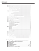
■ Contents ■ Contents________________________________________________________2 ■ Safety Instructions ________________________________________________3 PRODUCT SAFETY NOTICE ____________________________________3 SERVICE PERSONNEL WARNING ______________________________3 SAFETY PRECAUTIONS ______________________________________3 ■ Specifications ____________________________________________________4 ■ Adjustments after Parts Replacement ________________________________5 ■ Circuit Protections ___________________
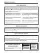
■ Safety Instructions SAFETY PRECAUTIONS WARNING: The chassis of this projector is isolated (COLD) from AC line by using the converter transformer. Primary side of the converter and lamp power supply unit circuit is connected to the AC line and it is hot, which hot circuit is identified with the line ( ) in the schematic diagram. For continued product safety and protection of personnel injury, servicing should be made with qualified personnel. The following precautions must be observed.
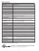
■ Specifications Projector Type Multi-media Projector Dimensions (W x H x D) 13.11” x 3.52” x 9.96” (333mm x 89.5mm x 253mm) Net Weight 9.3 lbs (4.2 kg) (PLC-XU45), 9.8 lbs (4.4 kg) (PLC-XU46) LCD Panel System 0.9” TFT Active Matrix type, 3 panels Panel Resolution 1024 x 768 dots Number of Pixels 2,359,296 (1024 x 768 x 3 panels) Color System 6 color system (PAL, SECAM, NTSC, NTSC4.43, PAL-M and PAL-N) High Definition TV SIgnals 480i, 480p, 575i, 575p, 720p.
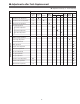
■ Adjustments after Parts Replacement ● : Adjustment necessary ❍ : Check necessary Optical Adjustments Disassembly / Replaced Parts LCD/ Prism Ass’y Condenser Lens Condenser lens adjustment ❍ ● Condenser lens-out adjustment ❍ Relay lens-out adjustment ❍ Condenser Lens-Out Relay Lens-Out Polarized glass R G B P. F.
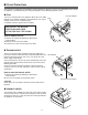
■ Circuit Protections This projector is equipped with the following circuit protections to operate in safety. If the abnormality occurs inside the projector, it will automatically turn off by operating one of the following protection circuits. ● Fuse The fuse is located inside of the projector. When either the LAMP Fuse indicator or the READY indicator is not illuminated, fuse may be opened. Check the fuse as following steps.
Circuit Protections ● Warning temperature and power failure protection The TEMP WARNING indicator flashes red and the projector will automatically turn off when the internal temperature of the projector exceeds the normal temperature or when stopping cooling fans or when the internal power supply lines are failed. Check the following possible causes and wait until stopping the TEMP WARNING indicator flashing. Possible causes - Air filter is clogged with dust particles.
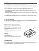
■ Mechanical Disassemblies Mechanical disassemble should be made following procedures in numerical order. Following steps show the basic procedures, therefore unnecessary step may be ignored. Caution: The parts and screws should be placed exactly the same position as the original otherwise it may cause loss of performance and product safety. Screws Expression (Type Diameter x Length) mm z Cabinet Top and Control Panel removal 1 Remove 4 screws A (M3x6) to take the Cabinet Top Ass’y upward off.
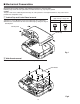
Mechanical Disassemblies c AV, DVI, Temp Board and Speaker removal 1 Remove 1 screw A (M4x8) to release grounding wires. 2 Pull the Rear Panel ass’y upward. 3 Remove 4 screws B (T3x6) and remove the AV Board. 4 Remove 4 screws C (T3x6) and remove the DVI Board. 5 Remove 4 screws D (T2.6x6) and remove the speaker. 6 Remove 1 screws E (T3x8) and remove the Sensor Board. Temp board E DVI board C B C B B B C AV board D D A Speaker Fig.
Mechanical Disassemblies b Lamp Ballast Unit removal 1 Remove 1 screw A (M3x4) and remove SW902, and then remove 1 screw B (M3x6) and disconnect the Lamp Socket. 2 Remove 2 screws C (M3x6) to take the Lamp Ballast ass’y upward off. 3 Remove 2 screws D (T2x6) to take the isolation sheet off. 4 Remove 4 screws E (T3x6) to take the lamp ballast board off. C D D E C E E Isolation sheet E B Lamp ballast board Lamp ballast socket A SW902 Fig.
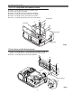
Mechanical Disassemblies m Power Box Cover and Fans(FN901, FN906) removal 1 Remove 4 screws A (M3x12) to take the Fan(FN901) off. 2 Remove 4 screws B (M3x8) to take the Fan(FN906) off. 3 Remove 3 screws C (M3x6) to take the Power Box Cover A upward off. A FN906 A A C B B B B C C Power box cover FN901 Fig.7 , Optical Unit removal (1) 1 Remove 1 screw A (M3x6) to take the Lamp Cover off. 2 Loosen 3 screws B to take the Lamp assembly by pulling the handle. Step to next procedure.
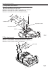
Mechanical Disassemblies , Optical Unit removal (2) Step from previous procedure. 3 Remove 6 screws C (M3x8) to take the Optical Unit upward upward off. To mount optical unit, mount optical unit first then mount the Lamp assembly and Lamp Cover. C C C C C C Optical unit Fig.8-2 . Power and P.F. Board removal 1 Remove 4 screws A (T3x6), 4 screws B (T3x8) to take the Power Board ass’y upward off. 2 Remove 4 screws C (M3x6) to take the P. F. Board from the Power Board.
Mechanical Disassemblies ⁄0 Fan (FN905) removal 1 Remove 1 screw A (M3x6) and take a Washer, A Spring and Interlock Switch lever. 2 Pull the Fan and duct ass’y upward, then remove the Interlock switch lever 2 screws B (M3x6) to take the Fan (FN905) off. B B FN905 Fig.10 ⁄1 Fans (FN902, FN903, FN904) removal A A 1 Remove 8 screws A (T3x8) and to take the Fan A Duct Top off and remove the Fans (FN902, FN903, FN904).
■ Optical Parts Disassemblies Before taking this procedure, remove Cabinet Top and Main Board following to the “Mechanical Disassemblies”. Disassembly requires a 2.0mm hex wrench and a screwdriver. z Projection Lens removal 1 Remove the Front Panel following to “Front Panel Removal” on “Mechanical Disassemblies”. 2 Remove 4 screws (M3x10) to take the Projection Lens ass’y off. Fig.1 x Integrator Lens-In disassembly 1 Remove 2 screws A (M2.5x6) and pull the Integrator Lens-In ass’y upward.
Optical Pats Disassemblies c Condenser lens disassembly 1 Remove 2 screws A (M2.5x6) and pull the Condenser Lens ass’y upward. 2 Remove 4 screws B (M2x4) to take the Lens off from the holder. A A B Condenser Lens Holder B B B * Lens should be placed as the flat surface side comes to the holder side. Fig.3-2 Fig.3-1 v Condenser Lens-Out disassembly 1 Remove 2 screws A (M2.5x6) and pull the Condenser Lens-Out ass’y upward. 2 Remove 2 screws B (M2x4) to take the Lens off from the holder.
Optical Parts Disassemblies b Relay Lens-Out disassembly 1 Remove 2 screws A (M2.5x6) and pull the Relay Lens-Out ass’y upward. 2 Remove 2 screws B (M2x4) to take the Lens off from the holder. Note: There is no mounting direction of the lens. A B A Holder B Relay Lens-Out Fig.5-2 Fig.5-1 n Polarized Glass-In removal 1 Remove each screw (M2.5x6) and pull the Polarized Glass-In ass’y upward. 2 Unhook the stoppers and take the glass off upward.
Optical Parts Disassemblies m Polarized Glass-Out/Pre-Polarized Glass removal 1 Remove 4 screws A (M2.5x4) and take the LCD/Prism ass’y off upward from the optical unit. 2 Remove each screw B and take the glass off upward. A Note: Do not replace the LCD panel separately otherwise it can not obtain proper picture. A A LCD Panel/ Prism Ass’y LCD Panel/Prism Ass’y Polarized Glass-Out B Optical filter LCD Panel * Glasses should be placed as the film attached side comes to the LCD panel side. Fig.
Optical Parts Disassemblies Locations and Directions Key No. When mounting or assembling the optical parts in the optical unit, the parts must be mounted in the specified location and direction as shown in figure below.
■ LCD Panel/Prism Ass’y Replacement IMPORTANT NOTICE on LCD Panel/Prism Ass'y Replacement LCD panels used for this model can not be replaced separately. Do not disassemble the LCD Panel/Prism Ass’y. These LCD panels are installed with precision at the factory. When replacing the LCD panel, should be replaced whole of the LCD panels and prism ass’y at once. After replacing LCD Panel/Prism ass’y, please check the following adjustments.
■ Lamp Replacement WARNING: ORDER REPLACEMENT LAMP - For continued safety, replace with a lamp assembly of the Type No. Service Parts No. Model same type. POA-LMP63 610 304 5214 PLC-XU45 - Allow the projector to cool for at least 45 minutes before you PLC-XU46 open the lamp cover. The inside of the projector can become POA-LMP56 610 305 8801 very hot. - Do not drop the lamp module or touch the glass bulb! The glass can shatter and cause injury.
■ Optical Adjustments Before taking optical adjustments below, remove the Cabinet Top and Main Board following to the “Mechanical Disassemblies” Adjustments require a 2.0mm hex wrench and a slot screwdriver. When you adjust Condenser lens, Condenser lens-out or Relay lens adjustment, you need to disconnect some connectors and FPC cables of LCD panels on the main board.
Optical Adjustments Condenser Lens adjustment 1 Turn the projector on by a state of without FPC cables. 2 Project only green light on the screen. 3 Adjust the adjustment base of condenser lens assy to make color 4 uniformity in green. 1) If the shading appears on the left or right of the screen as shown in Fig.2-1, loosen 2 screws A with the 2.0mm hex driver, and adjust the slot B to make color uniformity in green by using a slot screwdriver.
Optical Adjustments Condenser Lens-Out adjustment 1 Turn the projector on by a state of without FPC cables. 2 Project green and blue lights on the screen. 3 Adjust the adjustment base of condenser lens-out assy to make color uniformity in cyan. 1) If the shading appears on the left or right of the screen as shown in Fig.3-1, loosen 1 screw A with the 2.0mm hex driver, and adjust the slot B to make color uniformity in cyan by using a slot screwdriver.
Optical Adjustments Relay lens-Out adjustment 1 Turn the projector on by a state of without FPC cables. 2 Project all of lights on the screen. 3 Adjust the adjustment base of relay lens assy to make color uniformity in white. 1) If the shading appears on the left or right of the screen as shown in Fig.4-1, loosen 1 screw A with the 2.0mm hex driver, and adjust the slot B to make color uniformity in white by using a slot screwdriver.
■ Electrical Adjustments ● Service Adjustment Menu Operation To enter the service mode To enter the “Service Mode”, press and hold the MENU and IMAGE button on the projector at the same time for more than 3 seconds. The service menu appears on the screen as follows. To adjust service data Select the adjustment group no. by pressing the MENU (+) or IMAGE (-) button, and select the adjustment item no.
Electrical Adjustments ● Circuit Adjustments CAUTION: The each circuit has been made by the fine adjustment at factory. Do not attempt to adjust the following adjustments except requiring the readjustments in servicing otherwise it may cause loss of performance and product safety. [Adjustment Condition] ● Input signal Video signal .......................... 1.0Vp-p/75Ω terminated, 16 steps gray scale (Composite video signal) Computer signal .................... 0.
Electrical Adjustments 12x Pedestal adjustment 12v Signal Center adjustment 1. Receive the 16-step grey scale video signal. 2. Set to VIDEO mode. 3. Enter the service mode. 4. Connect an oscilloscope to test point “TP201R” (+) and chassis ground (-). 5. Select group no. “3”, item no. “14” and change data value to adjust the pedestal level and black level to be the same level. 6. Connect an oscilloscope to test point “TP201G” (+) and chassis ground (-). 7. Select group no. “3”, item no.
Electrical Adjustments n PC Offset adjustment , AV Gain adjustment 1. Receive the 16-step gray scale computer signal. 2. Set to COMPUTER mode. 3. Enter the service mode. 4. Connect an oscilloscope to test point “TP25R1” (+) and chassis ground (-). 5. Select group no. “3”, item no. “11” and change data value to adjust the waveform “a” (black portion ) to be maximum amplitude. 6. Connect an oscilloscope to test point “TP25G1” (+) and chassis ground (-). 7. Select group no. “3”, item no.
Electrical Adjustments 1⁄0 Gamma Shift adjustment [PC-GAMMA OFF ADJUSTMENT] 1. Receive the 16-step gray scale computer signal. 2. Set to COMPUTER mode. 3. Enter the service mode, select group no. “2”, item no. “6” and change data value to reproduce the proper gray scale picture on the screen. [AV-GAMMA OFF ADJUSTMENT] 4. Receive the 16-step gray scale video signal. 5. Set to VIDEO mode. 6. Enter the service mode, select group no. “2”, item no.
Electrical Adjustments ● Service Adjustment Data Table No. Adjustment Item Group: 0 TB1274 0 TINT 1 SHP_EQ 2 SHP_FO 3 SHP_GAIN 4 Y_OUT_LEVEL 5 C_OUT_LEVEL 6 Y_DELAY 7 COL_SYS 8 X'TAL 9 NOISE_DET 10 V_FREQ 11 Vert.
Electrical Adjustments No.
Electrical Adjustments No.
Electrical Adjustments No.
Electrical Adjustments Test Points and Locations ● MAIN BOARD TP52R TP11SC TP52G TP52B TP11SY TP62V TP62H TP11CV TP25G1 TP201G TP11PB TP201B TP11PR TP25G2 TP201R TP3551 IC4101 TP205 K25R K25B K25G IC301 TP25B2 TP25R1 TP25B1 TP25R2 TPDVS TPDCLK TP12V2 TP3581 IC401 IC801 K8P TP12V1 TPDHS -34-
■ Troubleshooting No Power The possible causes of No Power are listed below. Please check following and refer to power supply and protection circuits diagram in the figure opposite. 1. Stop the operation of power supply circuit due to detection of abnormality. - Detected the abnormality on the secondary power supply lines. Power failure detection diodes detect an abnormal voltage on the power supply. Check the shortage of secondary circuits, ICs, condensers, etc.
Troubleshooting Power supply drive and protection diagrams and locations SW902 IC2881 F601 SW904 SW902 Thermal sw. Interlock sw. F601 Fuse AC IN IC4881 SW904 1 1 3 3 TSW611 4 1 3 5 TEMP. SENSOR BOARD K6E 7 1 4 7 FN905 FN906 K6F 1 4 2 1 K8B K8H 3 1 5 K6J 2 LAMP_ERR IC671 6V K6K K6M K6L K8E K8S 15.
Troubleshooting No Picture 3. No picture from DVI source. The possible causes of No Picture are listed below. Please check following and refer to video signal processing diagrams in the figure opposite. 1. No picture from Video source Composite Video Input Check composite video signal at pins 45 and 46 of K10U on the AV Board and K3U on the Main Board. Check Y, C signals at pins 7 and 9 of IC2101.
VIDEO/Y Pb/Cb Pr/Cr S-VIDEO IC5161 33 34 35 36 45 46 49 50 51 52 39 41 80 | 90 22 1 3 5 CG1/CG2 16 18 20 16 8 9 CG1/CG2 Cr Cb CV CV/Y TP11CV TP11PB TP11PR Y/C 5 2 3 13 14 11 13 9 4 2 19 Y 7 7 C C_SWIN IC2101 DIGITAL COMB FILTER 9 5 23 22 IC1101 VIDEO 18 DECODER 21 17 43 44 MAIN BOARD 5 11 B R G R G B Cr Cb Y 16 18 20 8 12 V H 1 5 13 11 12 10 4 8 Y Pb Pr HS_OUT VS_OUT IC6101 INVERTER 5 1 2 2 4 6 V H IC6171 AFC 16 DET TP52B TP
Troubleshooting No Sound 1. No audio signals at AV input circuit. Check MUTE signal at pin 1 of IC001. Mute On : Low Check MUTE signal at pin 7 of IC1831, pins 7 and 13 of IC1881, and peripheral circuit. Mute On : High Check sound volume signal at pin 4 of IC001, and pin 14 of IC1831.Check IC IC001, IC1831 and peripheral circuit. Volume Min.: Low Check audio signals at pins14 and 15 of IC5011 on the AV Board. Check IC5011 and peripheral circuits. 2. Incorrect operation of VIDEO/COMPUTER mode switching.
■ Control Port Functions ● System Control & I/O Port Table (IC801) Pin No.
Control Port Functions Pin No.
Control Port Functions ● IIC Bus I/O Expander (IC1851) Port Functions Pin No. 1 2 3 4 5 6 7 8 9 10 11 12 13 14 15 16 Name S SCL SDA D0 D1 D2 D3 VSS D4 D5 D6 D7 VDD CS2 CS1 CS0 Function Action Reset IIC SCL IIC SDA CARD_IN VIEWER_ON SCDT1 TURBO_LED GND WARNING_LED LAMPREP_LED READY_LED Not used 5V Chip Select 2 Chip Select 1 Chip Select 0 Open Active “L” Active “L” L: CARD H: No CARD L: VIEWER Unit exist DVI Sync.
Control Port Functions ● IIC Bus DA Converter (IC2161) Port Functions Pin No.
■ Waveform VIDEO-IN Y-IN C-IN Y-OUT CB-OUT CR-OUT H-SYNC OUT V-SYNC OUT R-OUT G-OUT B-OUT R-DRIVE G-DRIVE B-DRIVE -44-
Waveform H-SYNC OUT V-SYNC OUT H-SYNC IN H-SYNC DRIVE V-SYNC DRIVE DHS DVS NRS R-S&H OUT G-S&H OUT BALLAST SW -45- B-S&H OUT
■ Cleaning After long periods of use, dust and other particles will accumulate on the LCD panel, prism, mirror, polarized glass, lens, etc., causing the picture to darken or color to blur. If this occurs, clean the inside of optical unit. Remove dust and other particles using air spray. If dirt cannot be removed by air spray, disassemble and clean the optical unit. Cleaning with air spray Disassembly Cleaning 1. Remove the cabinet top following to “Mechanical Disassemblies”. 2.
■ IC Block Diagrams ● AD8183ARU, AD8185ARU ● BA6287F -47-
IC Block Diagrams ● BA7078AF ● CXA2101AQ -48-
IC Block Diagrams ● CXD2064Q ● L3E01031 -49-
IC Block Diagrams ● L3E06070 ● L3E07050 -50-
IC Block Diagrams ● ML60851 ● M62393 -51-
IC Block Diagrams ● TB1274AF
IC Block Diagrams ● FA7612CA ● STR-Z2156 -53-
-54-
■ Electrical Parts List ME3-XU4500, MF3-XU4600 Product safety should be considered when a component replacement is made in any area of a projector. Components indicated by a ! mark in this parts list and the circuit diagram show components whose value have special significance to product safety. It is particularly recommended that only parts specified on the following parts list be used for components replacement pointed out by the mark.
ME3-XU4500, MF3-XU4600 Electrical Parts List Note: Parts order must contain Chassis No., Part No., and Descriptions. ● OUT OF CIRCUIT BOARD A901 Ballast Board Key SW Board P.F.
ME3-XU4500, MF3-XU4600 Electrical Parts List Key No. Part No. Description ASSEMBLIED BOARDS (ME3-XU4500, PLC-XU45) ! ! ! ! ! ! ! ! ! 610 610 610 610 610 610 610 610 610 292 299 299 301 301 301 301 304 304 5609 7330 7347 0939 0946 0953 0960 8925 8932 ASSY,PWB,KEY SW MS6A ASSY,PWB,AV MK8A ASSY,PWB,DVI MK8A ASSY,PWB,POWER MK8A * ASSY,PWB,P.F.
ME3-XU4500, MF3-XU4600 Electrical Parts List Key No. Part No. SW6812 Description 645 026 2791 Key No.
ME3-XU4500, MF3-XU4600 Electrical Parts List Key No. C012 C013 C1041 C1042 C1061 C2023 C2811 C2812 C2813 C3011 C3012 C3013 C3017 C3018 C3019 C3041 C5001 C5002 C5011 C5012 C5013 C5014 C5021 C5022 C5031 C5051 C5061 C5101 C5102 C5108 C5111 C5121 C5131 C5141 C5151 C5161 RESISTOR RC2811 R001 R011 R012 R013 R014 R016 R017 R1016 R1017 R1018 R1021 R1023 R1024 R1026 R1041 R1042 R1043 R1044 R1061 R1065 R1066 Part No. Description Key No.
ME3-XU4500, MF3-XU4600 Electrical Parts List Key No. Part No. Description Key No.
ME3-XU4500, MF3-XU4600 Electrical Parts List Key No. Part No.
ME3-XU4500, MF3-XU4600 Electrical Parts List Key No. Q65C Q651 Q66A Q661 Q662 Q67A Q67P Q671 Q672 Q68A Q68P Part No.
ME3-XU4500, MF3-XU4600 Electrical Parts List Key No. C686 C69Z C691 C692 C693 C694 C695 RESISTOR R5501 R5502 R5503 R5504 R5505 R5506 R5551 R5552 R5553 R5554 R5555 R5556 R63B R63C R63D R63E R632 !R633 R634 R635 R636 R637 R638 R643 R645 R65A R65B R65C R65E R65G R65H R65J R65K R65L R65P R65Q R65V R65W R65X R65Y R651 R652 R653 R654 R655 R656 R657 R658 R659 R66A R66B R66C R660 R661 R662 R663 R664 R67A R67B Part No. Description Key No.
ME3-XU4500, MF3-XU4600 Electrical Parts List Key No. Part No. L694 L695 Description 645 001 4512 645 020 1776 DIODE (ME3-XU4500, PLC-XU45) D5501 407 206 6308 407 179 1706 D5551 407 222 5903 407 179 6305 (MF3-XU4600, PLC-XU46) D5501 407 209 4509 407 187 7806 D5551 407 209 4509 407 187 7806 D631 D633 D636 D65A D65B D651 D652 D653 D654 D661 D67P INDUCTOR,10U K INDUCTOR,3.3U M ZD UDZS-TE-176.8B ZENER DIODE UDZ6.8B-TE-17 ZD UDZS-TE-176.8B ZENER DIODE UDZ6.
ME3-XU4500, MF3-XU4600 Electrical Parts List Key No. R62R R620 R623 Part No. Description 401 177 2208 401 259 9002 401 105 5301 VARIABLE RESISTOR VR611 645 002 3460 MT-GLAZE MT-GLAZE MT-GLAZE Key No. 5.6M JA 1/16W 150K FA 1/2W 4.
ME3-XU4500, MF3-XU4600 Electrical Parts List Key No. Q1161 Q131 Q132 Q151 Q152 Q171 Q172 Q1816 Q1817 Q1818 Q1819 Q2506 Q2516 Part No.
ME3-XU4500, MF3-XU4600 Electrical Parts List Key No. Q3113 Q3162 Q3163 Q3171 Q3172 Q3181 Q3182 Q3591 Q3592 Q4171 Q4172 Q6126 Q6127 Q6137 Q8101 Q8102 Q8141 Part No.
ME3-XU4500, MF3-XU4600 Electrical Parts List Key No. IC401 IC4101 IC4186 IC501 IC5211 IC5241 IC5251 IC5261 IC5271 IC5281 IC5291 IC531 IC561 IC6101 IC6121 IC6141 IC6171 IC6201 IC6241 IC6251 IC6261 IC6271 IC6281 IC6621 IC6631 IC6641 IC6651 IC6661 IC6671 IC8001 IC8002 IC801 IC8051 IC8061 IC8071 IC8081 IC8101 IC8111 IC841 IC9801 CAPACITOR C1101 C1102 C1103 C1104 C1105 C1106 C1107 C1108 C111 C1111 C1112 C1113 C1114 C1115 C1116 C1117 C1118 C1119 C112 Part No. Description Key No.
ME3-XU4500, MF3-XU4600 Electrical Parts List Key No. C1539 C154 C1541 C1542 C1543 C1561 C1562 C1563 C1564 C1566 C1567 C1568 C1569 C1571 C1572 C1573 C1581 C1582 C1583 C171 C1801 C1811 C1812 C1821 C1826 C1831 C1832 C1833 C1834 C1861 C1871 C1881 C201 C202 C203 C204 C205 C206 C2101 C2102 C2103 C2104 C2105 C2106 C211 C2111 C2112 C2113 C2117 C2118 C2119 C2121 C2124 C2126 C2127 C213 C2161 C2162 C2163 Part No.
ME3-XU4500, MF3-XU4600 Electrical Parts List Key No. C3127 C313 C3132 C314 C3142 C316 C3161 C317 C318 C319 C321 C322 C323 C324 C3532 C3533 C3534 C3536 C3538 C3539 C3551 C3552 C3553 C3562 C3563 C3564 C3566 C3568 C3569 C3581 C3582 C3583 C3584 C3592 C3801 C3802 C3803 C3804 C3806 C3821 C3831 C3841 C3842 C3843 C3844 C401 C402 C403 C404 C406 C407 C408 C409 C4102 C4103 C4104 C4105 C4106 C411 Part No.
ME3-XU4500, MF3-XU4600 Electrical Parts List Key No. C5217 C5218 C5219 C522 C5231 C5232 C5233 C5241 C5242 C5243 C5244 C5246 C5247 C5248 C5251 C5252 C5253 C5256 C5257 C5258 C5259 C5261 C5271 C5272 C5273 C5274 C5276 C5277 C5278 C5286 C5287 C5288 C5296 C5297 C5298 C531 C532 C533 C534 C536 C537 C538 C539 C541 C542 C543 C551 C552 C561 C562 C563 C564 C566 C567 C568 C569 C571 C572 C573 C581 C582 C6101 Part No.
ME3-XU4500, MF3-XU4600 Electrical Parts List Key No. C6633 C6634 C6642 C6643 C6644 C6652 C6653 C6654 C6662 C6663 C6664 C6665 C6672 C6673 C6674 C6675 C8001 C8002 C8003 C8004 C8005 C8006 C801 C8011 C8012 C8013 C8014 C8016 C8017 C8019 C802 C8021 C8022 C8023 C8024 C8026 C8027 C8028 C8029 C8051 C8052 C8053 C8062 C8063 C8072 C8073 C8082 C8101 C8102 C811 C812 C813 C814 C841 C842 C843 Part No.
ME3-XU4500, MF3-XU4600 Electrical Parts List Key No. RB413 RB414 RB415 RB416 RB501 RB502 RB503 RB531 RB532 RB533 RB561 RB562 RB563 RB8001 RB8002 RB8003 RB8004 RB8005 RB8006 RB8007 RB8008 RB8011 RB8012 RB8013 RB8014 RB9801 RB9802 R110 R1101 R1102 R1103 R1104 R1105 R1106 R1122 R1123 R1127 R1129 R113 R1131 Part No.
ME3-XU4500, MF3-XU4600 Electrical Parts List Key No. R152 R153 R1532 R1533 R154 R156 R1562 R1563 R157 R158 R1581 R1582 R1583 R1584 R1586 R1587 R1588 R1589 R159 R1591 R1592 R1593 R171 R172 R173 R174 R176 R177 R178 R1801 R1802 R1816 R1817 R1818 R1819 R1831 R1832 R1833 R1834 R1836 R1837 R1851 R1852 R1853 R1855 R1861 R1862 R1863 R1864 R1876 R1877 R1878 R1879 R1881 R1882 R1883 R1884 R1888 R1889 R1891 R1892 R1896 R201 R204 R206 R207 R208 Part No.
ME3-XU4500, MF3-XU4600 Electrical Parts List Key No. Part No.
ME3-XU4500, MF3-XU4600 Electrical Parts List Key No. R336 R338 R344 R346 R348 R349 R352 R3531 R3532 R3534 R3535 R3537 R3538 R3539 R354 R3540 R3541 R3543 R3544 R3545 R3546 R3547 R3552 R3553 R3556 R3558 R356 R3561 R3562 R3563 R3564 R3565 R3567 R3568 R3569 R3570 R3571 R3573 R3574 R3575 R3576 R3577 R358 R3581 R3582 R359 R3591 R3592 R3593 R3594 R361 R362 R364 R366 R368 R371 R3801 R3802 R3803 R3804 R3806 R381 R3821 R3822 R3823 R383 R3831 Part No.
ME3-XU4500, MF3-XU4600 Electrical Parts List Key No. R433 R434 R436 R437 R438 R439 R441 R442 R443 R444 R446 R447 R448 R449 R451 R457 R458 R459 R461 R462 R463 R464 R466 R467 R468 R469 R471 R472 R473 R501 R504 R5201 R5202 R5203 R5204 R5205 R5208 R521 R5210 R5211 R5212 R5216 R5217 R5218 R5221 R5222 R5223 R5224 R5225 R5226 R523 R5231 R5232 R5233 R5234 R5235 R5236 R524 R5241 R5243 R5245 R5248 R5251 R5252 R5253 R5254 R5255 Part No.
ME3-XU4500, MF3-XU4600 Electrical Parts List Key No. R6179 R6183 R6184 R6187 R6188 R6189 R6201 R6206 R6207 R6208 R6211 R6221 R6231 R6232 R6237 R6241 R6242 R6243 R6244 R6251 R6252 R6253 R6254 R6271 R6272 R6273 R6274 R6281 R6283 !R6601 !R6602 !R6606 !R6607 !R6616 R6622 R6623 R6624 R6652 R6661 R6671 R6672 R6681 R8001 R8002 R8006 R8007 R8008 R801 R8011 R8012 R8013 R8018 R802 R8021 R8022 R8023 R8024 R8028 R8029 R803 R804 R806 R807 R808 R8081 R8082 R8083 Part No.
ME3-XU4500, MF3-XU4600 Electrical Parts List Key No. R896 R899 R9801 R9803 R9806 R9807 R9811 R9812 R9813 R9814 R9816 R9822 Part No. 401 401 401 401 401 401 401 401 401 401 401 401 105 105 105 105 105 105 105 105 105 105 105 105 Description 0405 0603 5400 1501 7909 7909 8005 0405 0405 0405 0405 7909 MT-GLAZE MT-GLAZE MT-GLAZE MT-GLAZE MT-GLAZE MT-GLAZE MT-GLAZE MT-GLAZE MT-GLAZE MT-GLAZE MT-GLAZE MT-GLAZE Key No. 100 10K 47K 1.5K 0.000 0.000 1M 100 100 100 100 0.
ME3-XU4500, MF3-XU4600 Electrical Parts List Key No. RESISTOR R4881 R4882 R4884 Part No. Description 401 105 0306 401 105 0306 401 105 0603 MT-GLAZE MT-GLAZE MT-GLAZE Key No.
■ Mechanical Parts List ME3-XU4500, MF3-XU4600 Note: Parts order must contain Chassis No., Part No., and Descriptions.
ME3-XU4500, MF3-XU4600 Mechanical Parts List ● Optical Parts 44 44 47 56 47 47 44 44 47 47 -82- 57
ME3-XU4500, MF3-XU4600 Mechanical Parts List 44 44 54 45 45 67 (Red) 68 (Green) 69 (Blue) 45 -83-
ME3-XU4500, MF3-XU4600 Mechanical Parts List 43 43 43 53-a (Red) 53-b (Green) 53-c (Blue) 53 *Polarized glass 53-d (Red) 53-e (Green/Blue) *Optical filter(WV) 44 44 47 47 61 -84-
ME3-XU4500, MF3-XU4600 Mechanical Parts List 45 45 45 45 52 52 52 Model PLC-XU46 Model PLC-XU45 52-a 52-a -85-
ME3-XU4500, MF3-XU4600 Mechanical Parts List 63 55 51 66 64 62 70 57 58 71 60 59 65 -86-
ME3-XU4500, MF3-XU4600 Mechanical Parts List Key No. Part No. Description Key No. SCREWS 41 42 43 44 45 46 47 CABINET PARTS 1 610 292 5630 BUTTON CONTROL-MS6A 2 610 292 5647 BUTTON ZOOM-MS6A 3 610 292 5654 BUTTON POWER-MS6A 4 610 297 2283 CABINET TOP-MD8A (ME3-XU4500, PLC-XU45) 5 610 298 6686 CABINET RING-MF8A 6 610 301 8706 CABINET FRONT SERVICE-MF8 (Including Key No.
(ME3A) Mar. 2003 BB 400 Printed in Japan SANYO Electric Co., Ltd.
■ Diagrams & Drawings ME3-XU4500, MF3-XU4600 Schematic Diagrams Printed Wiring Board Drawings Model Chassis No. PLC-XU45 PLC-XU46 ME3-XU4500 MF3-XU4600 These schematic diagrams and printed wiring board drawings are part of the service manual original for chassis No. ME3-XU4500, MF3-XU4600 models PLCXU45, PLC-XU46. File with the service manual No. SM5110464-00. Note: All the information of part numbers and values indicated on these diagrams are at the beginning of production.
■ Parts description and reading in schematic diagram 1. The parts specification of resistors, capacitors and coils are expressed in designated code. Please check the parts description by the following code table. 2. Some of transistors and diodes are indicated in mark for the substitution of parts name. Please check the parts name by the following code table. 3. Voltages and waveforms were taken with a video color bar signal(1Vp-p at 75 ohms terminated) and controls to normal. 4.
IC5211 CG1/CG2-RGB-SW 1 3 5 R G B 20 18 10 | 77 IC5241 AV/PC-RGB-SW IC3011 RGB AMP 20 18 TP52B 16 5 22 22 SDA2_5 SCL2_5 AFC DET 17 16 PC/AV-SW IC6201 SYNC-SW V-SYNC H IC3041 INVERTER V 3 IC6241 SYNC DET.
■ Power Supply Lines LINE FILTER BOARD F601 FUSE AC CORD SW902 SW904 THERMAL INTER LOCK SW. SW. L602 L601 VA601 DB611 IC631 SWITCHING POWER SUPPLY D614 L611 T651 CONVERTER TRANSFORMER K6E K6F 1,2 D651 1 8 K6C K6B Q611 11 C642 IC681, Q681 PC641 IC671, Q671 Q672 3 5VS 5V AUDIO 5-6 29,39 9V MCI K6R 6V AUDIO BALAST_AC1 K8P P-FAIL D6601 6V AUDIO 5V_SW LAMP_ERR 15.
A5 b A R1091 D3072 R1082 R1081 R3062 R1098 R3060 R1097 R3068 R3065 R1096 R3054 R1095 R3052 R1094 R3066 R1093 R3063 R1092 R3074 R3076 D3053 R3053 R3051 R1089 D3051 R1088 C3051 R1090 C7031 R7071 R7052 R7053 R7041 R7051 R7042 R7054 R1087 R1086 A Q7011 R7013 R7016 R3055 R5146 Q5141 R5143 R5141 C5108 R5142 R5154 Q5151 R5153 R R5126 R5136 R5117 R5116 R2012 R2013 R2014 R2015 R5164 C5161 R5161 R5163 R5162 R2011 C2003 C5102 R5124 C2001 R2001 R2003 R2002 Q5121 R5134 R5151 R2812 C2812 E
IC2571 1 R2572 C6654 C6672 R6672 R441 R442 R443 R444 R412 R411 14 C6674 C6675 R1861 1 R1863 IC1561 13 12 R567 C571 C1573 C1572 C569 R1564 R562 R561 R1563 R432 R433 R414 11 R413 7 44 45 C413 C418 8 10 1 1 C422 10 48 C411 R454 R457R458 R456R1896 1 TP302 5 16 TP25G2 TP25G1 O R521 R523 R522 C522 RB501 C521 25 24 IC1501 13 C1511 C513 C512 C504 C1571C1512 C1502 C1509 C1564 C1513 C1504 R1502R503R504 R1562 R1503 R1504 R1501 R506 R1561 R3594 RB415 R3593 RB416 C416 C417 88 89 8 8 41 IC
MAIN (SIDE:B) P.
POWER (SIDE:A) POWER (SIDE:B) D631 C639 C652 D652 X D632 D652 C634 R634 C657 D632 + C633 L694 7 R635 C651 X D651 C632 C693 Q661 L693 C694 Q691 2 3 2 1 3 4 1 3 4 L661 4 1 L692 2 C659 R637 C641 Q641 C65F C661 C686 C65F C692 C691 L681 4 1 5 8 C684 R686 C681 Q65A 3 4 C68A R672 PB2 4 R675 C672 4 R67G 6 Q67A C5553 R5506 L671 1 39 D69A Q69A R5505 MAIN “K8S” 2 C676 40 C676 K6S 1 K6M R5552 D5561 R67Q R5567 4 1 1 K6U 3 3 1 C5563 K6R
KEY SW (SIDE:A) R6821 LINE FILTER (SIDE:A) SW6812 R6819 MAIN “K8A” 1AA4B10C 3250C_C K6B 1 R6833 R6831 12 R6823 D6833 D6832 READY(G) 215004 T4AH 3 LF901 R6834 C6803 R6812 3 NEUT C6802 R6813 D6831 P-UP 1 LIVE SW902 SW904 1 D6803 D6802 D6804 R6822 LAMP REPLACE(Y) D6834 POWER(R) R6806 250V F601A 1AA4B10C2860A_BK68A TEMP WARNING(R) a side TYPE: K6A VA601 R6832 F601 L601 F601B POWER D6801 C603 C6801 R6804 C602 C601 R6807 C604 R6808 SW6806 P-RIGHT VOL+ P-LEFT VO
A10 PCB_ME3A
Schematic Diagrams PLC-XU45,46 Page A11 [Left] ■ Schematic Diagrams LINE FILTER BAORD A AC CORD 1AV4W11B 00800 AC100-120V AC200-240V THERMOSTAT SW INTE SW (SET TO OPEN AT 100+/-5 C) AT1 LF901 U20B30101 (LIVE) 1 (LIVE) K6A_1 K6A_2 NT2 NT2 K6A_3 K6A_4 NT2 NT2 F601 4A250V TCSL F601A J20B 00100 C602 275GM 0.22 UVCA C601 R601 275GM 1GJ 0.22 220K UVCA VA601 VEV 0043 C603 275GM 0.22 UVCA L601 F35B 1010N C604 275GM 0.
Schematic Diagrams PLC-XU45,46 THERMOSTAT SW [Right] INTER LOCK SW (SET TO OPEN T 100+/-5 C) SW902 A SW904 S10B3590N :S10B5070N :S10B5470N K903S J11B 2450N S10B3370N K901S J11B 2450N K902S J11B 2450N K904S J11B 2450N AV BOARD DVI BOARD LENS B 1AV4Z10B23200 RECTION ZOOM MOTOR P.F. BOARD M M FOCUS MOTOR 1AV4M10B 19100 FROM POWER K6U 1 2 D614 FML-G16S K10T J11MD540G C618 450GK 0.
Schematic Diagrams PLC-XU45,46 Page A12 [Left] IC3011 LT1399CSP RGB AMP A 1/16GJ1.5KC R3014 R_OUT F34EA207G D1001 UDZ 6.2B G_OUT COMPUTER MONITOR OUTPUT B_OUT R3011 1/16GJ 75C R1013 X -5VS R1017 1/16 GZ0C L1002 G_OUT F34EA207G D1002 UDZ 6.2B B 9 R1016 1/16 GZ0C L1001 R_OUT R1014 X B_OUT 5VS R1018 1/16 GZ0C L1003 F34EA207G C3012 25KZ0.1 GQFY C3011 6.
Schematic Diagrams PLC-XU45,46 40 IN_R K10V_39 IN_G K10V_37 IN_B K10V_35 40 39 39 K3V_39 NT1 38 K3V_37 35 36 K3V_35 K10V_29 K10V_27 30 33 34 31 32 29 30 27 28 25 26 23 24 21 22 19 20 17 18 29 NT1 NT1 RX1+ K10V_23 RX1- K10V_21 NT1 NT1 20 K10V_17 19 NT1 K10V_15 15 16 13 14 11 12 9 10 7 8 5 6 NT1 RXC+ K10V_11 RXC- K10V_9 9 NT1 K10V_5 3 K10V_3 4 NT1 2 1 40 39 40 39 NT1 5V DIO M220 :F1) 7 8 5 6 K3W_5 3 4 K3W_3 9 K10W_5 IN
Schematic Diagrams PLC-XU45,46 Page A13 [Left] A TP11SC J30B 1640G S_C 1 2 5 K3U_5 7 K3U_7 5V AUDIO NT1 12 J30B 1640G S_Y 15 S_Y 5VPC NT1 TP11SY K3U_15 9V NT1 17 9V R133 1/16GJ 100C 3.2V K3U_11 13 C131 25KZ 0.1 GQFZ R132 1/16GJ 1KC TP11SY -5VS NT1 9 11 S_C 5VS NT1 Q131 AH R131 1/16GJ 100C 3.2V K3U_1 3 B 9V TP11SC K3U J10ML540G L151 L2PD 3R3MG Q132 AH R134 1/16GJ 1KC C151 C152 16EM 25KZ 47WM 0.1 GQFZ Yout R152 1/16GJ 56KC R156 1/16GJ 1.8KC C153 6.
Schematic Diagrams PLC-XU45,46 Page A13 [Right] A 5V C1101 6.3EM 47WM C1107 6.3EM 47WM L1103 L2A7 4R7MG Y C1108 25KZ0.1 GQFZ C1102 25KZ 0.1 GQFZ 5V R1100 X X1101 V10B5050G S_C CV R1139 1/16GJ 1KC C1133 KK1000GQBZ C1111 25KZ0.1GQFZ C1113 25KZ0.1GQFZ C1114 KZ0.01GQFZ B_BLK_DC MACRO 1 3 B1_IN G1_IN R1_IN 8 9 10 11 12 13 14 1101_3 C1112 25KZ 0.1 GQFZ SDA VIDEO_CB R1143 1/16 GJ 1KC Q1141 2SA 1037 AKR VIDEO_Y VIDEO_Y C C1161 CJ15 CGQY 25KZ0.1GQFZ 25KZ0.
Schematic Diagrams PLC-XU45,46 Page A14 [Left] A VIDEO_R VIDEO_R VIDEO_G VIDEO_G VIDEO_B VIDEO_B CG1/CG2 B CG1/CG2-SW. C IN_R IN_R IN_G IN_G IN_B IN_B IN_H IN_H IN_V IN_V IC5211 AD8185ARU R5210 1/16 GZ0C R5211 1/16 GZ0C R5212 1/16 GZ0C 1 CG1-R +5V 24 2 GND SW2 23 3 CG1-G SW1 22 4 +5V 21 GND C5216 25KZ 0.1 GQFZ C5217 25KZ 0.1 GQFZ 6 +5V -5V D C5231 6.3EM 22D C5232 6.3EM 22D C5233 6.
Schematic Diagrams PLC-XU45,46 Page A14 [Right] GRE0 GRE1 GCLK GFBK GRE2 A GRE3 GRE4 TP207 TP206 J30B 1640G J30B 1640G GRE5 GRE6 GRE7 GRO0 GRO1 GRO2 GRO4 GRO5 GRO6 C239 X R221 R222 C 1/16GJ47C 1/16GJ100C GRO3 GRO7 3.3VS 3.3VAS C201 6.3EM220WM :6.3EM220F1 3 4 IN I-IN R5295 X J30B 1640G TP21_B1 C5296 CD10 CGQY R5296 1/16GJ 1KC R5297 1/16GJ 8.2KC C233 25KZ 0.1 GQFZ B_IN1 X NT2 C298 25KZ 0.1 GQFZ R208 1/16 GJ 1.8KC GHSFOUT C223 25KZ 0.1 GQFZ R209 1/16 GJ 1.
Schematic Diagrams PLC-XU45,46 Page A15 [Left] GBE0 GBE1 GBE2 C RB301 R1HA1034G :R1A41034G GBE3 GBE4 GBE5 GBE6 GBE7 GGO0 GGO1 GGO2 RB303 R1HA1034G :R1A41034G GGO5 GGO6 VB0 VG7 VG6 VG5 VG4 VG3 VG2 VG1 VG0 VR7 VR6 VR5 VR4 VR3 VR2 VR1 VR0 VG6 VG5 VG4 VG3 VG2 VG1 VG0 VR7 VR6 VR5 VR4 VR3 VR2 VR1 VR0 GGE1 GGE2 RB304 R1HA1034G :R1A41034G X R376 18 17 16 15 14 13 12 11 10 9 8 7 6 5 4 3 2 1 A18 A17 A16 A15 A14 A13 A12 A11 A10 A9 A8 A7 A6 A5
Schematic Diagrams PLC-XU45,46 Page A15 [Right] A P-SCL2 P-SDA2 B TP1302 TP1301 J30B 1640G J30B 1640G CONTROL MEMORY 3.3VS IC1301 24LC16BT/SN-T P-SDA2 P-SCL2 P-SDA R1302 R1303 X X 1 A0 2 A1 3 A2 4 VSS VDD TEST 7 SCL 6 SDA 5 C P-SDA P-SCL P-SCL R363 X TP301 IC1311 TP1311 J30B 1640G RESET R1312 1/16 GZ0C 3.3VS C1311 25KZ 0.
Schematic Diagrams PLC-XU45,46 Page A16 [Left] KEYSW.LED K8A J10EZ120G A 1 3.3VS K8A_1 3.3VS NT2 K8A_2 5VS 5VS NT2 K8A_3 KEYSW1 K8A_4 KEY SW BOARD "K68A" R2821 1/16GJ470C R2822 1/16GJ470C R2823 1/16GJ470C KEYSW2 KEYSW2 NT2 K8A_5 KEYSW3 IC801 50-52 KEYSW1 NT2 KEYSW3 NT2 K8A_6 TURBO_LED R2824 1/16 GJ 10KC NT2 K8A_7 GND NT2 GND LAMP_LED NT2 K8A_10 READY_LED D2821 UDZ12B R2826 1/16 GJ 10KC C2821 25KZ 0.1 GQFZ R2825 1/16 GJ 10KC K8A_9 NT2 C2822 25KZ 0.
Schematic Diagrams PLC-XU45,46 Page A16 [Right] A D/A IC1831 M62392FP 3.3VS G SCL2 SERVICE MEMORY 1/16GJ100C R1802 1/16GJ100C IC1801 24LC16BT/SN-T 11 D7 12 VDD 13 A0 14 VSS 15 A1 16 A2 17 A3 18 A4 19 A5 20 A6 R1819 1/16GJ 4.7KC SDA1_5 D SDA1_5 SCL4 SDA4 SDA2 SCL2 SDA1 SCL1 VIEWER_TXD VIEWER_RXD LAMP_BST_SW P_S_0 1/16GJ4.7KC 1/16GJ4.7KC 1/16GJ4.
Schematic Diagrams PLC-XU45,46 Page A17 [Left] 15.5V A R503 X STSQEB STSQOB 1/16GZ0C SHCLKB C512 25KZ0.1 GQFZ R506 X R504 XFRB L501 L2A73R3MG C504 25KZ0.1 GQFZ C501 6.3EM100 (WM:F1) 3.3V C513 25KZ0.1 GQFZ R3593 1/16GJ 4.
Schematic Diagrams PLC-XU45,46 D3591 1SS355 15.5V 15VL 15.5V R3592 1/16GJ 4.7KC R2591 1/8GZ000 K25BB X L2591 L2A7 3R3MG R2592 X C2591 16EM100D :16EM100F1 D2591 X Q3592 AH R3593 1/16GJ 4.7KC C503 16EM 47WM L3591 1/8GJ10 R3591 1/16GJ 1.5KC C3592 16EM10D :16EM10F1 [Right] P.FAIL P_FAIL Q3591 2SA1203Y Page A17 C2502 25KZ0.1 GQFZ K25B J11EA300G K25B_1 NT1 1 DY K25B_2 NT1 R3594 1/16GJ 10KC 2 CLY K25B_3 NT1 3 CLY K25B_4 NT1 C2501 25KZ0.1 GQFZ 3.
Schematic Diagrams PLC-XU45,46 Page A18 [Left] A B C D E F G H I J K L 1 2 3 4 5 A18 -15- 6 7 8 9
Schematic Diagrams PLC-XU45,46 Page A18 [Right] A B C D E F G H I J K 9 10 11 12 13 14 15 16 SCH_ME3A -16-
■ Pin description of diode, transistor and IC ME3-XU4500, MF3-XU4600 ● Diode ● Diode K K K A A K K A K: Cathode A: Anode A A K K A A ● Transistor/FET ● Transistor/FET C C1 C2 C C2 B1 E1 C: Collector B: Base E: Emitter Index E E C C B E B E2 B2 C1 E1 B2 B1 B1 B B1 E B2 E C1 C2 B E E FET E C B B C E C B D: Drain G: Gate S: Source E C B2 C1 C2 S B1 G C1 C2 B2 D S E2 D G ● IC● IC 2 (GND) 2 Vdd 3 3 2 3 1 2 3 1 1 Index 3 RESET 2 1 GND Index 12