Multimedia Projector MODEL PLV-Z2 Owner’s Manual
Table of Contents Table of Contents 2 To the Owner 3 Safety Instructions 4 Air Circulation Installing the Projector in Proper Position Moving the Projector 5 5 5 Compliance 6 Connecting the AC Power Cord 7 Features and Design 8 Part Names and Functions 9 Front Back Bottom Terminal Top Remote Control Remote Control Operating Range Remote Control Batteries Installation 9 9 9 10 11 12 13 13 Installation 14 Positioning the Projector Adjustable Feet Moving the Lens Connecting to Video Equipme
To the Owner Before operating this projector, read this manual thoroughly and operate the projector properly. This projector provides many convenient features and functions. Operating the projector properly enables you to manage those features and maintains it in better condition for a considerable time. Improper operation may result in not only shortening the product-life, but also malfunctions, fire hazard, or other accidents.
Safety Instructions All the safety and operating instructions should be read before the product is operated. Read all of the instructions given here and retain them for later use. Unplug this projector from AC power supply before cleaning. Do not use liquid or aerosol cleaners. Use a damp cloth for cleaning. This projector should be operated only from the type of power source indicated on the marking label.
Safety Instructions Air Circulation Installing the Projector in Proper Position Openings in the cabinet are provided for ventilation and to ensure reliable operation of the product and to protect it from overheating, and these openings must not be blocked or covered. Install the projector properly. Improper Installation may reduce the lamp lifetime and cause a fire hazard. Do not tilt the projector more than 20 degrees to either side. 20˚ CAUTION Hot air is exhausted from the exhaust vent.
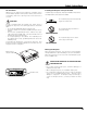
Compliance Federal Communication Commission Notice Note : This equipment has been tested and found to comply with the limits for a Class B digital device, pursuant to part 15 of the FCC Rules. These limits are designed to provide reasonable protection against harmful interference in a residential installation. This equipment generates, uses and can radiate radio frequency energy and, if not installed and used in accordance with the instructions, may cause harmful interference to radio communications.
Compliance Connecting the AC Power Cord This projector uses nominal input voltages of 100-120 V or 200-240 V AC. This projector automatically selects the correct input voltage. It is designed to work with single-phase power systems having a grounded neutral conductor. To reduce risk of electrical shock, do not plug into any other type of power system. Consult your authorized dealer or service station if you are not sure of the type of power being supplied.
Features and Design This Multimedia Projector is designed with the most advanced technology for portability, durability, and ease of use. This projector utilizes built-in multimedia features, a palette of 16.77 million colors, and matrix liquid crystal display (LCD) technology. ◆ Short Zoom Lens This projector is equipped with Short Zoom Lens which allows you to enjoy 100" screen size in range of 9.8' (3.0m) to 13.1' (4.0m).
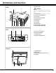
Part Names and Functions q Exhaust Vent Front q w CAUTION Hot air is exhausted from the exhaust vent. Do not put heat-sensitive objects near this side. w Air Intake Vent (The two arrows show air flow.
Part Names and Functions Terminal q e q w SERVICE PORT This jack is used to service this projector. e VIDEO Connect the composite video output from video equipment to this jack. (p16) * 10 DVI-I RGB/COMPONENT Connect computer output (Digital/Analog DVI-I type), component video output, or RGB Scart 21-Pin video output to this terminal. (p16, 17) A built-in micro processor which controls this unit may occasionally malfunction and need to be reset.
Part Names and Functions Top q w e r ON-OFF POWER WARNING LAMP REPLACE MENU INPUT SELECT t y u i q POWER ON–OFF button Turns the projector on or off. (p18) t MENU button Opens or closes the On-Screen Menu. (p21) w POWER indicator Flashes red until the projector gets ready to be turned on or when the front cover is closed. It lights red when the projector is in the stand-by mode. It remains green while the projector is under operation.
Part Names and Functions q LIGHT switch Slides upward and lights the following buttons for about 10 seconds: SCREEN, ONOFF, LAMP, MENU, SELECT, INPUT, and IMAGE ADJ. w SCREEN button Selects a screen size. (p30, 38) e LAMP button Selects a lamp mode. (p41) r MENU button Opens or closes the On-Screen Menu. (p21) t POINT (UP/DOWN/LEFT/RIGHT) button Selects an item or adjusts value in the On-Screen Menu. These are also used to pan the image in the Digital zoom mode.
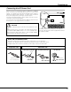
Part Names and Functions Remote Control Operating Range Point the remote control toward the projector (Infrared Remote Receiver) whenever pressing any button. Maximum operating range for the remote control is about 16.4’ (5m) and 60° in front of the projector. 16.4’ (5 m) 60° Remote Control Batteries Installation 1 Remove the battery compartment lid. 2 Slide the batteries into compartment. Pull up the lid and remove it. 3 Replace the compartment lid.
Installation Positioning the Projector This projector is designed to project on a flat projection surface and can be focused from 3.9’(1.2m) - 20.0’(6.1m). Refer to the figure and the table below for the screen size and the distance between the projector and the screen. 20.0' (6.1m) 15.1' (4.6m) 200” (Inch Diagonal) 9.8' (3.0m) 150” 3.9' (1.
Installation Moving the Lens The projection lens can be moved up, down, left, and right with the manual lens shift function. This function makes it easy to provide a projected image where you want. Turn the lens shift ring (left/right) left/right to move the lens leftward / rightward. Turn the lens shift ring (up/down) up/down to move the lens upward / downward.
Installation Connecting to Video Equipment (Video, S-Video) Video, S-Video Use the supplied video cable or a s-video cable (not supplied). Video Equipment Composite Video Output S-VIDEO Output S-Video Cable Video Cable (RCA x 1) VIDEO S-VIDEO NOTE ● The S-VIDEO jack has priority over the VIDEO jack under the condition of connecting both the S-VIDEO jack and the VIDEO jack when selecting AUTO in the Input Menu (p24).
Installation Connecting to Video Equipment (RGB Scart) RGB Scart Video Equipment Use a Scart-DVI cable (option). RGB Scart 21-pin Output Scart-DVI Cable DVI-I RGB/COMPONENT Connecting to a Computer Computer (Digital/Analog) Use a DVI cable (option) for digital. Use a DVI-VGA cable (option) for analog. IBM-compatible or Macintosh computer Monitor Out DVI Cable DVI-VGA Cable DVI-I RGB/COMPONENT NOTE ● See page 55 for ordering optional cables.
Basic Operation Turning On the Projector 1 Complete peripheral connections (with a computer, VCR, etc.) before turning on the projector. 2 Connect the projector's AC power cord into an AC outlet and open the front cover. Turn the Main On/Off switch on, and the POWER indicator flashes red in a moment and turns on red. (The POWER indicator continues to flash red slowly if the front cover is being closed. ) Open the front cover.
Basic Operation Zoom Adjustment Move the Zoom Lever to zoom in and out. Zoom Lever Focus Adjustment Rotate the Focus Ring to adjust the projected picture focus. Focus Ring Aperture (Contrast) Adjustment Move the Aperture Lever to adjust contrast.
Basic Operation Keystone Adjustment If a projected picture has keystone distortion, correct the image with KEYSTONE adjustment. 1 Press the KEYSTONE ▲/▼ button on the remote control or select the Keystone in the Setting Menu (p39). The Keystone dialog box appears. 2 Correct keystone distortion by pressing the KEYSTONE ▲/▼ button or the Point Up/Down button.
Basic Operation On-Screen Menu You can control and adjust this projector through the On-Screen Menu. Refer to the following pages to operate each adjustment on the On-Screen Menu. Remote Control SELECT button MENU button 1 Press the MENU button to display the On-Screen Menu (Main Menu). 2 Select a menu from the main menu by pressing the Point Up/Down button, and press the Point Right button to enter the sub-menu. (The selected icon turns yellow.
Basic Operation Menus VIDEO MENUS Input Menu: selects video input source. (p23-25) AV System Menu: selects video system from AUTO, PAL, SECAM, NTSC, NTSC4.43, PAL-M, PAL-N, 1080i, 1035i, 720p, 575p, 480p, 575i, 480i. (p26) Image Select Menu: selects image level from Standard, Cinema, Game, and Image 1 ~ 4. (p27) Image Adjust Menu: adjusts Contrast, Brightness, Color, Tint, Color temp., White balance (R/G/B), Sharpness, Gamma, Auto grayscale, Progressive, Film, Reset, Store.
Video Input Input Source Selection (INPUT 1 Terminal/Video, S-Video, Component) Direct Operation INPUT button Choose Input 1 by pressing the INPUT button on the top control or on the remote control. Before using these buttons, correct input source should be selected through the INPUT 1 buttons on the remote control or through menu operation as described on the next page.
Video Input Menu Operation 1 Select the Input Menu with the Point Up/Down button, and then press the Point Right button to enter the sub-menu. 2 Select Input 1 with the Point Up/Down button and then press the Point Right button. The Source Select Menu will appear. 3 Move the pointer to the source that you want to select and then press the SELECT button. Auto When selecting the AUTO button, the projector automatically detects incoming video signal, and adjusts itself to optimize its performance.
Video Input Input Source Selection (INPUT 2 Terminal/HDCP, Component, Scart) Direct Operation INPUT button INPUT button Choose Input 2 by pressing the INPUT button on the top control or on the remote control. Before using these buttons, correct input source should be selected through menu operation as described below.
Video Input Video System Selection 1 Select the AV System Menu with the Point Up/Down button, and then press the Point Right button to enter the sub-menu. 2 Choose the system that you want to select with the Point Up/Down button and then press the SELECT button. AV System Menu (Video or S-Video) Video or S-Video Auto The projector automatically detects incoming video system, and adjusts itself to optimize its performance. When Video System is PAL-M or PAL-N, select system manually.
Video Input Image Level Selection Direct Operation Select an image level among Standard, Cinema, Game, Image 1, Image 2, Image 3, and Image 4 by pressing the IMAGE buttons (STANDARD (STD), PRESET IMAGE (P-IM), and 1-4 buttons) on the remote control. (Each time you press the PRESET IMAGE (P-IM) button, either Cinema or Game is selected.) Remote Control Standard (STD) Normal picture level preset on this projector. Cinema [PRESET IMAGE (P-IM)] Picture level adjusted for the picture with fine tone.
Video Input Image Level Adjustment 1 Select the Image Adjust Menu with the Point Up/Down button, and then press the Point Right button to enter the sub-menu. 2 Select an item with the Point Up/Down button and press the Point Left/Right button to adjust the item. Image Adjust Menu Contrast Press the Point Left button to decrease contrast and the Point Right button to increase contrast.
Video Input Sharpness Press the Point Left button to soften the image and the Point Right button to sharpen the image. (From -7 to +7) This arrow indicates that there are previous items. Select this item and press the Point Up button to go to the previous item. Gamma Press the Point Left/Right button to obtain better balance of contrast. (From -7 to +7) Auto grayscale When this function is "ON", it automatically enhances contrast of bright and dark part of image.
Video Input Screen Size Adjustment This projector has a useful function to resize a projected screen. 1 Select the Screen Menu with the Point Up/Down button, and then press the Point Right button to enter the sub-menu. 2 Select an item with the Point Up/Down button and press the Point Left/Right button to set the screen size. Screen Menu Full Provides an image to fit the width of the screen by expanding the width of the image uniformly.
Computer Input Input Source Selection Direct Operation Choose INPUT 2 by pressing the INPUT button on the top control or on the remote control. Before using these buttons, correct input source should be selected through menu operation as described below. INPUT button Input 2 Input 1 Top Control Remote Control INPUT SELECT INPUT button Menu Operation 1 Select the Input Source Selection Menu with the Point Up/Down button, and then press the Point Right button to enter the submenu.
Computer Input Computer System Selection This projector can detect most of the current computer systems with the Multi-scan system and the Auto PC adjustment function provided in the projector. When selecting computer input, the projector automatically displays the most proper image for the input signal. One of the following four displays appears on the system menu icon.
Computer Input Computer Adjustment (Auto) The Auto PC Adjustment function is provided to automatically adjust Fine sync, Total dots, Horizontal, and Vertical to conform to your computer. This function can be operated as follows. 1 Select the PC Adjust Menu with the Point Up/Down button, and then press the Point Right button to enter the sub-menu. 2 Choose the AUTO PC Adj. item and then press the SELECT button. PC Adjust Menu Auto PC Adj.
Computer Input Computer Adjustment (Manual) Some computers employ special signal formats which may not be tuned by Multi-scan system of this projector. This projector has Manual PC Adjustment to enable you to precisely adjust several parameters to match those signal formats. The projector has 5 independent memory areas to memorize those parameters manually adjusted. This enables you to recall the setting for a specific computer whenever you use it.
Computer Input Display area Select the resolution at the Display area dialog box. Display area H Adjusts the horizontal area displayed by this projector. Press the Point Left/Right button to decrease/increase value and then press the SELECT button. Display area V Adjusts the vertical area displayed by this projector. Press the Point Left/Right button to decrease/increase value and then press the SELECT button. Select Store to store adjustment data.
Computer Input Image Level Selection Direct Operation Select an image level among Standard, Real (P-IM), Image 1, Image 2, Image 3, and Image 4 by pressing the IMAGE buttons (STANDARD (STD), PRESET IMAGE (P-IM), and 1-4 buttons) on the remote control. Remote Control Standard (STD) Normal picture level preset on this projector. Real [PRESET IMAGE (P-IM)] Picture level with improved halftone for graphics. IMAGE 1~4 User preset image in the Image Adjust Menu (p37).
Computer Input Image Level Adjustment 1 Select the Image Adjust Menu with the Point Up/Down button, and then press the Point Right button to enter the sub-menu. 2 Select an item with the Point Up/Down button and press the Point Left/Right button to adjust the item. Image Adjust Menu Contrast Press the Point Left button to decrease contrast and the Point Right button to increase contrast.
Computer Input Screen Size Adjustment This projector has a useful function to resize a projected screen. 1 Select the Screen Menu with the Point Up/Down button, and then press the Point Right button to enter the sub-menu. 2 Select an item with the Point Up/Down button and press the Point Left/Right button to set the screen size. Normal Provides image to fit screen size. Full Provides an image to fit the horizontal size of the screen. True Provides image in its original size.
Setting Setting 1 Select the Setting Menu with the Point Up/Down button, and then press the Point Right button to enter the sub-menu. 2 Select an item with the Point Up/Down button to set various settings. Setting Menu (Language) Language The language used in the On-Screen Menu is available in English, German, French, Italian, Spanish, Portuguese, Dutch, Swedish, Russian, Chinese, Korean, or Japanese. Keystone When the image is distorted vertically, select the Keystone.
Setting Capture Capture This function is used to capture the image being projected and use it for a starting-up display or interval of presentations. After capturing the projected image, go to the Logo function and set it as “User”. Then the captured image will be displayed when turning on the projector next time or pressing the MY PICTURE (MY-P) button on the remote control. (p12) To capture the image, select [Yes]. To cancel the Capture function, select [No].
Setting Lamp mode Lamp mode This function allows you to change brightness of the screen. ···· normal brightness ···· the controlled brightness according with input signal ···· lowers brightness and reduces the lamp power consumption. Remote control This projector has two different remote control codes: Code 1 (initial code) and Code 2. This switching function prevents remote control interference when operating several projectors or video equipment together.
Maintenance and Cleaning Warning Indicator The WARNING indicator shows the state of the function which protects the projector. Check the state of the WARNING indicator and the POWER indicator to take proper maintenance. The projector is shut down and the WARNING indicator is flashing red When the temperature inside the projector exceeds the normal temperature, the projector is automatically shut down to protect the inside of the projector.
Maintenance and Cleaning Cleaning the Air Filter The air filter prevents dust from accumulating on the surface of the optical elements inside the projector. Should the air filter become clogged with dust particles, it will reduce cooling fans’ effectiveness and may result in internal heat build up and adversely affect the life of the projector. Clean the air filter following the steps below. 1 Turn off the projector and disconnect the AC power cord from the AC outlet.
Maintenance and Cleaning Cleaning the Projection Lens Follow these steps to clean the projection lens. 1 Disconnect the AC power cord before cleaning. 2 Softly wipe the projection lens with a cleaning cloth that contains a small amount of non-abrasive camera lens cleaner, or use lens cleaning paper or a commercially available air blower to clean the lens. Avoid using an excessive amount of cleaner. Abrasive cleaners, solvents, or other harsh chemicals might scratch the surface.
Maintenance and Cleaning Lamp Replacement When the life of the projection lamp of this projector draws to an end, the LAMP REPLACE indicator lights yellow. If this indicator lights yellow, replace the lamp with a new one promptly. Top Control POWER This indicator lights yellow when the life of the projection lamp draws to an end. WARNING LAMP REPLACE CAUTION CAUTION Allow a projector to cool, for at least 45 minutes before you open the Lamp cover. The inside of the projector can become very hot.
Maintenance and Cleaning Lamp Replace Counter Be sure to reset the lamp replace counter after the lamp is replaced. When the lamp replace counter is reset, the LAMP REPLACE indicator stops lighting. 1 Turn the projector on, press the MENU button, and the OnScreen Menu will appear. Select the Setting Menu with the Point Up/Down button and press the Point Right button to enter the sub-menu. 2 Select the Lamp counter reset item and then press the SELECT button.
Appendix Troubleshooting Before calling your dealer or service center for assistance, check the items below once again. – Make sure you have properly connected the projector to peripheral equipment as described in “Connecting to Video Equipment” and "Connecting to a Computer" on page16 and 17. – Make sure all equipment is connected to AC outlet and the power is turned on. – When you operate the projector with a computer and it does not project an image, restart the computer.
Appendix Problem: The Remote Control does not work. – Try these solutions. – Check the batteries. – Make sure no obstruction is between the projector and remote control. – Make sure you are not too far from the projector when using the remote control. Maximum operating range is 16.4’ (5m). – Make sure the code of the remote control is conformed to that of the projector. (See page 41) WARNING : High voltages are used to operate this projector. Do not attempt to open the cabinet.
Appendix Indicators and Projector Condition Check the indicators for projector condition. Indicators POWER WARNING LAMP REPLACE red/green red yellow Projector Condition The Main On/Off switch is off or the AC power cord is unplugged. • • • lights green. ✽ The projector is preparing for stand-by and the front cover is closed. Or the projection lamp is being cooled down. The projector cannot be turned on until cooling is completed.
Appendix Menu Tree Video Input/Computer Input Input Input 1 Input 2 Auto Go to System (1) or (2) Video Go to System (1) S-Video Go to System (1) Y, Pb/Pc, Pr/Cr Go to System (2) RGB( Analog ) Go to System (3) RGB( PC Digital ) N/A RGB( AV HDCP ) N/A Component Go to System (2) RGB( Scart ) N/A ✽N/A - - - not applicable Video Input System (1) Auto PAL SECAM NTSC NTSC 4.
Appendix Computer Input System (3) Mode 1 Mode 2 SVGA 1 ---- Screen Normal Full True Digital zoom ✽Systems displayed in the System Menu vary depending on an input signal. PC Adjust Auto PC Adj. Fine sync.
Appendix Compatible Computer Specifications Basically this projector can accept the signal from all computers with the V, H-Frequency below mentioned and less than 100 MHz of Dot Clock.
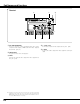
Appendix Technical Specifications Projector Type Dimensions (W x H x D) Net Weight LCD Panel System Panel Resolution Number of Pixels Color System High Definition TV Signal Scanning Frequency Projection Image size (Diagonal) Projection Lens Throw Distance Projection Lamp Video Input Jacks Computer/Video Input Terminal Service Port Connector Feet Adjustment Voltage and Power Consumption Operating Temperature Storage Temperature Remote Control Accessories Multimedia Projector 14.13" x 3.82" x 10.
Appendix Dimensions Unit : inch (mm) 4.52 (114.7) 14.13 (359) 11.8˚ (Max.) ON-OFF POWER 10.79 (274) WARNING LAMP REPLACE MENU INPUT SELECT 3.
Appendix Configurations of Terminal DVI-I RGB/COMPONENT TERMINAL (DIGITAL/ANALOG) Terminal : DVI-I Pin Configuration C1 C2 1 2 3 4 5 6 7 8 9 10 11 12 13 14 15 16 17 18 19 20 21 22 23 24 C3 C4 C5 C1 C2 C3 C4 C5 Analog Red Input Analog Green Input Analog Blue Input Analog Horiz. sync Analog Ground (R/G/B) 1 2 3 4 5 6 7 8 T.M.D.S. Data2– T.M.D.S. Data2+ T.M.D.S. Data2 Shield No Connect No Connect DDC Clock DDC Data Analog Vert. sync 9 10 11 12 13 14 15 16 T.M.D.S. Data1– T.M.D.S. Data1+ T.M.D.S.
Printed in Japan Part No. 610 309 7923 (1AA6P1P4276-- M4KA) SANYO Electric Co., Ltd.