
User's Manual


– 39 –
SM830043
3
3. Electrical data
3-1 Indoor Unit
33
33
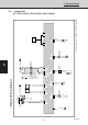
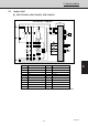
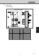
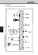
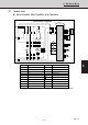
3 SPW-T253GS56, SPW-T363GS56, SPW-T483GS56
• Schematic Diagram
S 854-2-5268-500-00-1 (T253GS56, T363GS56, T483GS56)
2
1
3
FS
1
2
1
TR
Coil
TH1
CR-X363GS
Controller
1
1
3
5
F
2
1
2
1
3
2
DPH
RY2
RY1
RY4
RY5
3
2
LM
1
1
RY3
4P-1
4P-4
1
4P-2
RY5
FMI
C
12
1
735
456
RY1
RY2 RY2
HLM
3
2
1
1
17
3
49FMI
8
RY4
RY4
Symbols Description
FMI
49FMI
C
F
DPH
LM
TR
RY1-RY5
TH1
TH2
Indoor Fan Motor
Indoor Motor Thermal Protector
Capacitor
Fuse
Dew Proof Heater
Auto Louver Motor
Power Transformer
Auxiliary Relay
Thermistor (Indoor Coil)
Room Thermistor
Symbols Description
CR-X363GS
IND
SW
Indoor Controller
Indicator Lamp Assy
Switch Assy
Terminal Plate
Connector
Terminal
3
1
2
IND
3
1
2
7
1
9
1
7
1
SW
2
1
Room
TH2