TECHNICAL & SERVICE MANUAL STK-RCS-7TWSUA FILE NO. Destination: North America WIRED REMOTE CONTROLLER Model No. STK-RCS-7TWSUA Product Code No. 1 852 353 85 REFERENCE NO.
Important! Please Read Before Starting When Transporting Be careful when picking up and moving the indoor and outdoor units. Get a partner to help, and bend your knees when lifting to reduce strain on your back. Sharp edges or thin aluminum fins on the air conditioner can cut your fingers. This air conditioning system meets strict safety and operating standards. As the installer or service person, it is an important part of your job to install or service the system so it operates safely and efficiently.
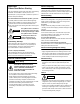
Table of Contents Page 1. SPECIFICATIONS ......................................................................................................................... 4 2. APPLICABLE INDOOR UNITS ..................................................................................................... 5 3. FUNCTIONS ................................................................................................................................. 5 4. SELF-DIAGNOSTICS .............................................
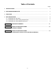
1. SPECIFICATIONS Item Signal Transmission Method Power Source Display Panel Type Temperature Airflow Direction Display Items Time Temperature Sensor Functions Operation Section Room Temperature Detection 1. When the indoor unit is modified from one for wireless remote controller to that for wired remote controller, some of the functions becomes unavailable. Therefore, before such modification, make sure to receive an approval of the client. Also, the self-diagnostics procedure is changed.
2. APPLICABLE INDOOR UNITS Type Indoor Unit Model No. Ceiling Cassette Type XHS1271, XHS1872, XS1271, XS1872 KHS0971, KHS1271, KHS1872, KHS2472 Wall Mounted Type KS0971, KS1271, KS1872, KS2472 KMHS0772, KMHS0972, KMHS1272, KMHS1872, KMHS2472 KMS0772, KMS0972, KMS1272, KMS1872, KMS2472 3. FUNCTIONS When the unit is modified from one for wireless remote controller to that for wired remote controller, the following functions become unavailable.
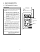
4. SELF-DIAGNOSTICS 4-1. Self-Diagnostics Procedure < Clock display > PROCEDURE Test run mode After turning on power to the air conditioner, use the remote controller and follow the steps below to execute selfdiagnostics. Self-diagnostics mode Step 1: Press and hold the remote controller NIGHT SET BACK (NSB) button and 1 HR TIMER button. Then, press and hold the ACL (reset) button with a pointed object such as the tip of a pen.
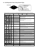
4-2. Self-Diagnostics Table (Ceiling Cassette Type) INDOOR UNIT OPERATION button OPERATION lamp TIMER lamp HIGH POWER lamp REMOTE CONTROL receiver Since the indications cover various units, the corresponding parts listed below may not be present in some models. .... OFF Indication on indoor unit OPERATION Timer HIGH POWER Code Diagnostics items ....
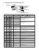
4-3. Self-Diagnostics Table (Wall Mounted Type) INDOOR UNIT (1) OPERATION lamp (2) TIMER lamp (3) QUIET lamp ION lamp OPERATION button REMOTE CONTROL receiver Since the indications cover various units, the corresponding parts listed below may not be present in some models. .... OFF Indication on indoor unit Quiet (3) Timer (2) Operation (1) Code .... Blinking Diagnostics items ....
APPENDIX A INSTRUCTION MANUAL STK-RCS-7TWSUA (OI-852-6-4181-139-00-0) A-1
00_STK-RCS-7TWSUA_Cover.fm Page 1 Tuesday, February 24, 2009 11:37 AM STK-RCS-7TWSUA INSTRUCTION MANUAL Wired Remote Controller This wired remote controller is designed for both the “COOL/DRY/HEAT Model” and “COOL/DRY Model” indoor unit. Before using the remote controller, be sure to confirm the “model type” specified on the front cover of the INSTRUCTION MANUAL supplied with the indoor unit.
01_STK-RCS-7TWSUA_EN.fm Page 2 Thursday, March 12, 2009 5:14 PM CONTENTS Page PRODUCT INFORMATION ................................................................................................................ 2 ALERT SYMBOLS .............................................................................................................................. 2 INSTALLATION LOCATION ................................................................................................................
01_STK-RCS-7TWSUA_EN.fm Page 3 Thursday, March 12, 2009 5:14 PM FEATURES • Microprocessor Controlled Operation • Automatic Restart Function for Power Failure • 24-Hour ON or OFF Timer • Automatic Switching between Cooling and Heating (This function is available only for “Single use” of COOL/DRY/ HEAT Model.) • 1-Hour OFF Timer • Night Setback • Hot Start Heating System (This function is available only for COOL/DRY/HEAT Model.
01_STK-RCS-7TWSUA_EN.fm Page 4 Thursday, March 12, 2009 5:14 PM REMOTE CONTROL UNIT NOTE The descriptions on the AUTO ( “COOL/DRY Model.” ) or HEAT ( ) operation mode are only for the “COOL/DRY/HEAT Model,” and not for the Display Information on the operating conditions is displayed while the remote control unit is switched on. If the unit is turned off, only the mode that was set previously is still displayed. Temperature setting buttons (TEMP.) Press the button to increase the set temperature.
01_STK-RCS-7TWSUA_EN.fm Page 5 Thursday, March 12, 2009 5:14 PM ON/OFF operation button This button is for turning the air conditioner on and off. MODE selector button Use this button to select AUTO, HEAT, DRY, COOL or FAN mode. (AUTO) : When this setting is selected, the air conditioner calculates the difference between the thermostat setting and the room temperature and automatically switches to the ‘‘COOL’’ or ‘‘HEAT’’ mode as appropriate.
01_STK-RCS-7TWSUA_EN.fm Page 6 Thursday, March 12, 2009 5:14 PM OPERATION WITH THE REMOTE CONTROL UNIT 1. Automatic Operation (only for COOL/DRY/HEAT Model) 2. Manual Operation • Single use This unit automatically switches between cooling operation and heating operation according to the difference between the room temperature and the temperature setting.
01_STK-RCS-7TWSUA_EN.fm Page 7 Thursday, March 12, 2009 5:14 PM 3. Adjusting the Fan Speed A. In Cooling and DRY Mode: ( A. Automatic fan speed Simply set the FAN SPEED selector button to the position. This automatically sets the best fan speed for the room temperature. B.
01_STK-RCS-7TWSUA_EN.fm Page 8 Thursday, March 12, 2009 5:14 PM SETTING THE TIMER 3. How to set the ON time (Example) To start operation at 7:10 am. ON TIME Present time Operation 1. How to set the present time Indication 1. Press the SET button once. The timer indication alone flashes and the previous settime is only displayed. 2. • Press the HH button until The display will change automatically back to show the present time after about 10 sec. AM 7 is displayed.
01_STK-RCS-7TWSUA_EN.fm Page 9 Thursday, March 12, 2009 5:14 PM USING THE 1-HOUR OFF TIMER 1. 1-Hour OFF Timer This function causes the unit to operate for one hour and then stop, regardless of whether the unit is on or off when this button is pressed. The indicator in the display indicates that this function is operating. Setting procedure: Regardless of whether the unit is operating or stopped, press the 1 HR. TIMER button. appears in the display.
APPENDIX B INSTALLATION INSTRUCTIONS (STK-RCS-7TWSUA) STK-RCS-7TWSUA (II-852-6-4190-481-00-1) A-2
09-027 STK-RCS-7TWSUA 3/10/09 12:46 PM Page 1 INSTALLATION INSTRUCTIONS IMPORTANT • In order to install this wired remote controller onto a wall-mounted model, the connection kit (STK-KCW1), which must be purchased separately, is required. • Once the wired remote controller is connected, the wireless remote controller cannot be used. I Parts supplied with the remote controller Table 1 Parts See Table 1.
12:46 PM Page 2 A. Installing with in-wall junction box (1) Install the junction box (locally purchased) into the wall. (Figs. 2-a and 3) (2) Pass the wire harness through the junction box and conduit. (Fig. 3) (3) Insert a flathead screwdriver into the 5 tab locations and disconnect the back plate of the remote controller by lifting up slightly. (Fig. 2-b) The tabs are thin; take care not to chip them.
12:46 PM Page 3 I How to wire the remote controller Ceiling panel (1) Turn OFF the power and remove the ceiling panel air-intake grille. (Refer to 3-6-1 Before Installing the Ceiling Panel in the Installation Instructions supplied with the indoor unit.) (2) Remove the 3 power box cover screws and 2 control box cover screws, then remove both covers. At this time, take care not to drop the covers. (Fig.
09-027 STK-RCS-7TWSUA 3/10/09 12:46 PM Page 4 I How to Test Run the Air Conditioner After turning on the power of the air conditioner, use the remote controller and follow the steps below to conduct the test run. (1) Set the remote controller in Test Run mode. (Fig. 9) a)Press and hold the NIGHT SETBACK button and the 1HR. TIMER button. b)Then press and hold the ACL (Reset) button with a pointed object such as the tip of a pen. After 5 seconds, release the ACL button first.
APPENDIX C INSTALLATION INSTRUCTIONS Installing the Connection Kit for Wall-Mounted Models ( ) STK-KCW1 (II-852-6-4190-491-00-0) A-3
09-026 STK-KCW1 3/19/09 11:52 AM Page 1 INSTALLATION INSTRUCTIONS I Parts included in the package See Table 1. Table 1 Parts Figure Q'ty Parts Figure Q'ty Truss-head Phillips 5/32 13/32" (4 10mm) 1 Clamping strap Clamp 2 Wire tube Label 1 Tapping screw Wire (with a noise filter) Installation instructions Parts 1 Figure Q'ty 1 7-3/32"(180mm) 1 Top cover 1 I Installing the connection kit A. 7000 BTU, 9000 BTU, and 12000 BTU inverter models (1) Remove the air intake grille.
09-026 STK-KCW1 3/19/09 11:52 AM Page 2 (7) Feed the wire harness that was included in the wired remote controller package into the right lower rear of the unit and route it to the component box. (Fig. 4a) Component box • When feeding the wire harness through the opening, be careful of the motor cable and be sure to feed the wire harness and motor cable together through the opening. (Fig.
09-026 STK-KCW1 3/19/09 11:52 AM Page 3 B. 18000 BTU and 24000 BTU inverter models (1) Remove the air intake grille. (2) Remove the terminal cover. Pull out the thermistor, then remove the grille. • For details on steps (1) and (2), refer to the Installation Instructions included in the outdoor unit package. (3) Disengage the top cover from the tabs on the sides of the component box, then pull the cover toward you to remove it. (Fig.
09-026 STK-KCW1 3/19/09 11:52 AM Page 4 I How to Test Run the Air Conditioner After turning on the power of the air conditioner, use the remote controller and follow the steps below to conduct the test run. (1) Set the remote controller in Test Run mode. (Fig. 9) a) Press and hold the NIGHT SETBACK button and the 1HR. TIMER button. b) Then press and hold the ACL (Reset) button with a pointed object such as the tip of a pen. After 5 seconds, release the ACL button first.
SANYO Commercial Solutions A Division of SANYO North America Corporation 1300 Michael Drive, Suite A Wood Dale, IL 60191, U.S.A. Sanyo Canada Inc. 1-300 Applewood Crescent, Concord, Ontario L4K 5C7, CANADA Apr.